

Page 1
T
ECHNICAL INFORMATION
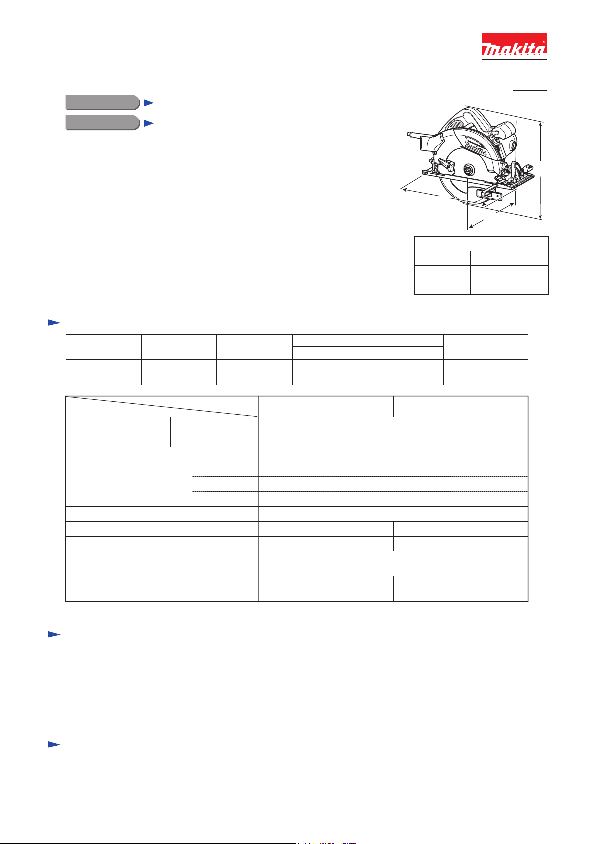
PRODUCT
P 1/16
Model No.
Description
HS7100, HS7101
Circular Saw 190mm (7-1/2")
CONCEPT AND MAIN APPLICATIONS
Models HS7100, HS7101 have been developed as the successor models of
the current model 5705R, featuring compact & lightweight design without
riving knife.
Other features are:
• New aesthetic design with black blade case and rear cover
• Electronic brake for quick blade stop (for HS7101 only)
• Twin LED job light for easy tracing of cutting line in the dark place
(for HS7101 only)
These models are also available with plastic carrying case as “K” models;
HS7100K, HS7101K.
Specification
Voltage (V) Cycle (Hz)
110 13 50/60 680 1,750
220 - 240 6.4 50/60
Current (A)
Continuous Rating (W)
Input Output
1,400
1,400 640 2,200
L
Dimensions: mm (")
Length (L)
Width (W)
Height (H)
Max. Output (W)
H
W
310 (12-1/4)
246 (9-11/16)
258 (10-1/8)
Specifications
Size of blade: mm (")
No load speed: rpm= min.
Max cutting capacity: mm (")
Electric brake No Yes
Power supply cord: m (ft)
Weight according to
EPTA-Procedure 2003/01*
*1: with TCT saw blade, Dust nozzle
Diameter
Hole diameter
ˉ¹
1: kg (lbs)
Model No.
0 degree
45 degrees
50 degrees
HS7100 HS7101
190 (7-1/2)
30 (1-3/16)
5,500
67.0 (2-5/8)
48.5 (1-15/16)
43.5 (1-11/16)
Double insulationProtection against electric shock
No Yes (twin LED)Job light
European countries: 4.0 (13.1), Australia, Brazil: 2.0 (6.6)
Other countries: 2.5 (8.2)
4.0 (8.8) 4.0 (8.9)
Standard equipment
TCT saw blade 190 ............. 1
Hex wrench ........................ 1
Guide rule (Rip fence) ....... 1
Dust nozzle ......................... 1
Guide rail adapter ............... 1 (for some countries only)
Note: The standard equipment for the tools shown above may vary by country.
Optional accessories
Saw blades
Guide rail 1400 set
Guide rail 1900 set
Guide rail 3000 set
Position seat sets
Rubber seat set
Seat set
Guide rail adapter
Bevel guide set
Guide rule (Rip fence)
Clamp set
Stopper
Page 2

P 2/16
Repair
CAUTION: Repair the machine in accordance with “Instruction manual” or “Safety instructions”.
[1] NECESSARY REPAIRING TOOLS
Code No. Description Use for
1R003 Retaining ring S pliers ST-2N Removing/mounting Retaining ring S-42, holding Safety cover
1R032 Bearing setting plate 8.2 Removing Spindle from Helical gear
1R207 45-degree set square Adjusting accuracy of 45 degrees
1R208 90-degree set square Adjusting accuracy of 90 degrees
1R217 Ring 22 Supporting Helical gear when removing Spindle
1R228 1/4” Hex shank bit for M4 Disassembling/assembling Rear angular guide
1R269 Bearing extractor Removing Ball bearing 607ZZ from Spindle
1R280 Round bar for arbor 6-50 Removing Spindle from Helical gear
1R340 Bearing retainer wrench Removing/mounting Bearing retainer 23-36
[2] LUBRICATION
Apply the following grease/ lubricant to the specific portions to protect parts and product
from unusual abrasion.
Item No. Description Grease AmountPortion to lubricate
39
48
75
Fig. 1
Blade case Gear room approx. 6 g
Angular guide Contact surface where (39) Blade case pivots
39
48
Safety cover
a littleBearing box Drum portion where Safety cover pivots
a little
Makita Grease SG No.0
VG100
75
Page 3
P 3/16
Repair
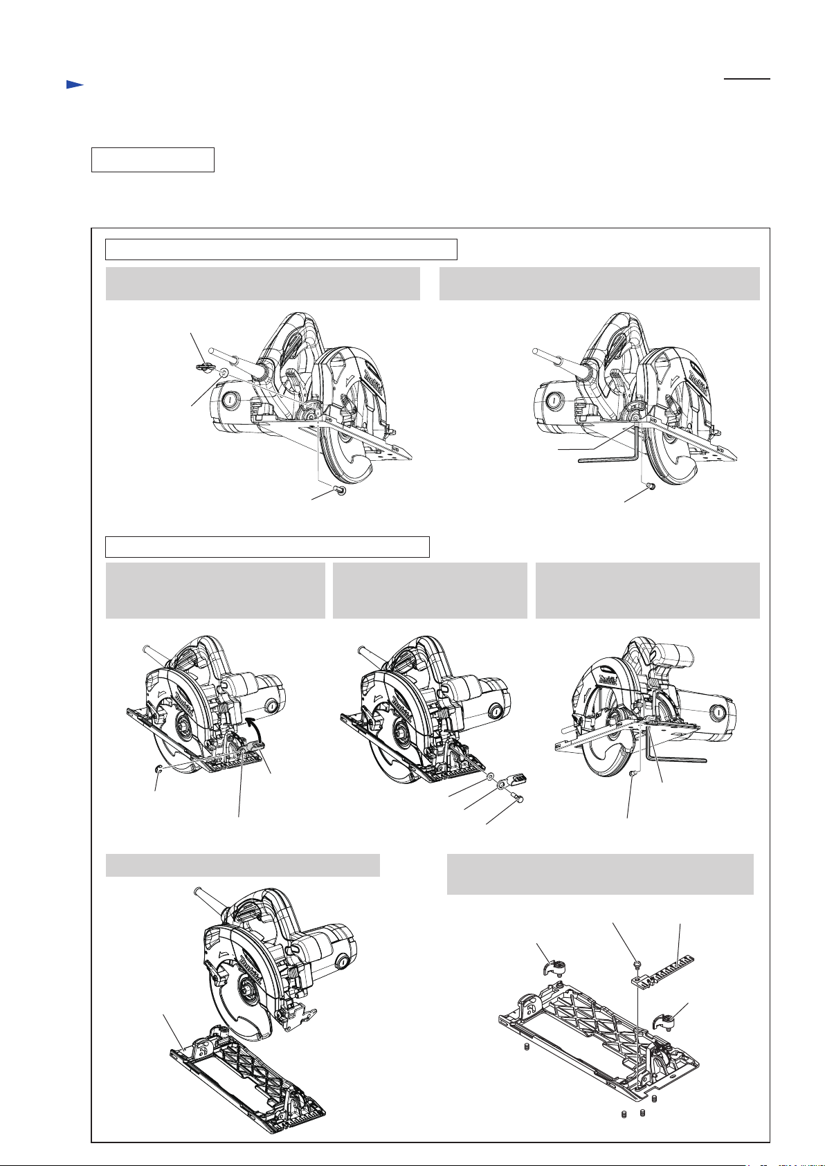
[3] DISASSEMBLY/ASSEMBLY
[3] -1. Base
DISASSEMBLING
Set the cutting depth of the machine to maximum, and remove saw blade.
Then remove both Rear angular guide section and Angular guide section from Base. Base can now be replaced. (Fig. 2)
Fig. 2
Rear Angular Guide Section (on the rear of the machine)
1. Unscrew M6 Thumb nut, then remove Flat washer 6
and M6x20 Flat head square neck bolt.
M6 Thumb nut
Flat washer 6
M6x20 Flat head
square neck bolt
Angular Guide Section (on the front of the machine)
3. Loosen M6x20 Hex bolt using
Lever 45, then remove E-8 Bow
stop ring with a slotted screwdriver.
4. Remove M6x20 Hex bolt
by using Lever 45 as a tool,
then remove Flat washer 6.
2. Loosen M6x8 Hex socket set crew with Hex wrench,
remove Shoulder pin 6-7 that functions as a hinge.
M6x8 Hex socket
set screw
Shoulder pin 6-7
5. Loosen M6x8 Hex socket set screw,
then remove Shoulder pin 6-7 that
functions as a hinge.
Lever 45
E-8 Bow stop ring
M6x20 Hex bolt
6. Base can now be separated from the machine.
Base
Flat washer 6
Lever 45
M6x20 Hex bolt
M6x8 Hex socket
set screw
Shoulder pin 6-7
7. Base can be replaced after removing Top guide,
Lock levers, and four M6x8 Hex socket set screws.
M5x8 Pan hd. screw
Lock lever
M6x8 Hex socket
set screw
(4 pcs.)
Top guide
Lock lever
Page 4
Repair
[3] DISASSEMBLY/ASSEMBLY
[3] -1. Base
ASSEMBLING
Base can be mounted to the machine by taking the reverse steps of Disassembling.
Note: Follow the important instructions described in Fig. 2A.
See Fig. 3 for Assembling and Adjustment of Lock lever for clamping Guide Rule.
Fig. 2A
P 4/16
Be sure to mount E-8 Bow stop ring as shown below
for securely engaging Lever 45 with M6x20 Hex bolt.
Angular guide section,
Angular guide
Flat washer 6
Lever 45
E-8 Bow stop ring
M6x20 Hex bolt
viewed from top
Adjust Lever 45 so that it can be locked in the position
shown below when the machine’s cutting angle is
adjusted to 90 degrees.
Lever 45
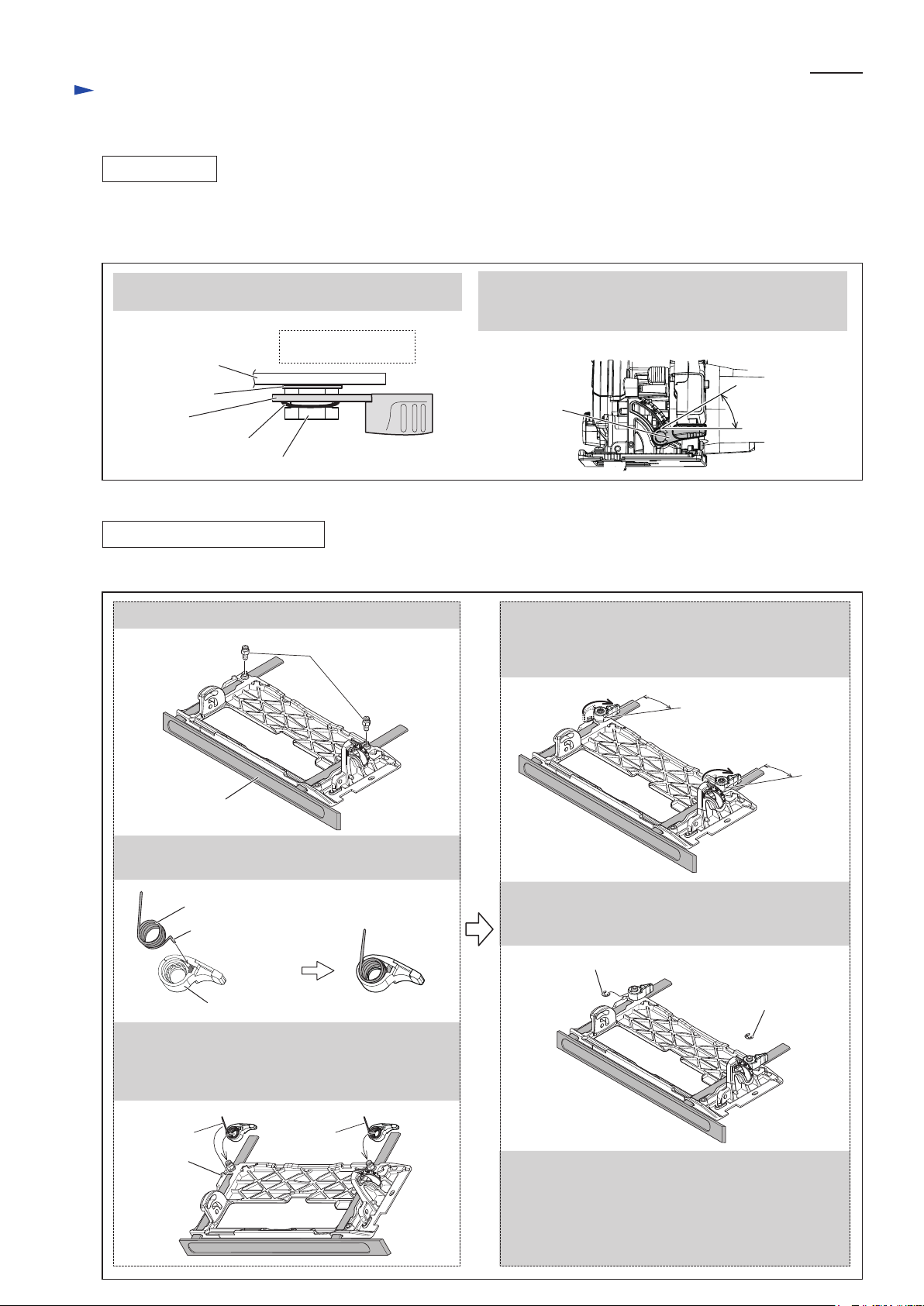
[3] -2. Lock Lever for clamping Guide Rule
ASSEMBLING, ADJUSTMENT
Mount Lock lever to Base and adjust its locking position when Guide rule attaching. (Fig. 3)
Fig. 3
1. Fasten Guide rule to Base with M6x10 Hex bolt.
M6x10 Hex bolt
4 . Lift up Lock lever so that its upper surface is flush
with that of M6x10 Hex bolt, then rotate Lock lever
independently. Then adjust the Lock lever so that
it can be locked in the position shown below.
30 degrees
30 degrees
Guide rule
2. Insert Torsion spring 11 into Lock lever with its
short arm inserting in the square hole of Lock lever.
Torsion spring 11
short arm
Lock lever
3. Applying the Torsion spring's long arm to the tab
of Base, put the Lock lever over M6x10 Hex bolt.
But do not push Lock lever down until you engage
it with the Hex bolt in the step 5.
long arm long arm
tab
30 degrees
5 . Push Lock lever down until it engages with
M6x10 Hex bolt, then secure Lock lever with
Stop ring E-6.
Stop ring E-6
Stop ring E-6
6. Make sure that:
1) When Guide rule is clamped, Lock lever stops
in the same position as you set in the step 4.
2) With Guide rule removed, Lock lever returns to
its initial position smoothly and exactly from the
locking position..
Page 5

Repair
[3] DISASSEMBLY/ASSEMBLY
[3] -3. Depth Guide
DISASSEMBLING
Disassemble Depth guide as described in Fig. 4.
Fig. 4
P 5/16
1. Set the cutting depth of the machine to minimum.
Remove Lock plate from Lever 70 by unscrewing
M4x8 Pan head screw.
M4x8
Pan head screw
3. Fix M4-7 Hex lock nut with Wrench 7, then remove
M4x20 Hex bolt with 1R288.
Lock plate
2. From M6x18 Hex bolt, remove Lever 70, M6 Hex nut,
Flat washer 6 and Sleeve 6.
M6 Hex nut
Lever 70
M6x18 Hex bolt
4. Depth guide and Flat washer 6 on Blade case side
can now be removed.
Flat washer 6
Sleeve 6
M4-7 Hex
lock nut
M4x20 Hex bolt
5. M6x18 Hex bolt can now be removed by loosening
M5x8 Hex socket set screw a little bit.
M6x18 Hex bolt
M6x18 Hex bolt
Depth guide
Flat washer 6
M5x8 Hex socket
set screw
Page 6

Repair
[3] DISASSEMBLY/ASSEMBLY
[3] -3. Depth Guide
ASSEMBLING
Assemble Depth guide section by taking the reverse step of Disassembling. (Fig. 4)
Note: Follow the important instructions described in Fig. 5.
Fig. 5
1. M6x18 Hex bolt must be mounted to Blade case so that the concave surface of the bolt head faces
M5x8 Hex socket set screw.
Blade case
M6x18 Hex bolt
Base
concave
surface
P 6/16
M5x8 Hex socket
set screw
2. M4x8 Pan head screw must be seen closest to Handle when Lever 70 is in the locking position
with the cutting depth of the machine adjusted to minimum.
Handle
Lever 70 in the locking position,
with the cutting depth of the machine
adjusted to minimum
M4x8 Pan head screw
Page 7

Repair
[3] DISASSEMBLY/ASSEMBLY
[3] -4. Angular Guide
DISASSEMBLING
Angular guide can be disassembled as described in Fig. 6.
Fig. 6
P 7/16
1. Loosen M6x20 Hex bolt
with Lever 45, then remove
E-8 Bow stop ring.
Lever 45
E-8 Bow stop ring
M6x20 Hex bolt
4. Hold M5-8 Hex lock nut with Wrench 8,
then unscrew M5 Truss head screw
O ring 9 and Stopper can now be removed.
2. Remove M6x20 Hex bolt
by using Lever 45 as a tool,
then remove Flat washer 6.
Flat washer 6
Lever 45
M6x20 Hex bolt
3. Loosen M6x8 Hex socket head set crew,
then remove Shoulder pin 6-7 that
functions as a hinge.
M6x8 Hex socket
Shoulder pin 6-7
5. Disassemble Angular guide.
set screw
Angular guide
O Ring 9
M5 Truss
head screw
Stopper
Angular guide
ASSEMBLING
Assemble Angular guide by taking the reverse step of Disassembling. (Fig. 6)
Note:
1. E-8 Bow stop ring must be mounted as shown on the left in Fig. 2A.
2. Adjust Lever 45 as shown on the right in Fig. 2A.
M5-8
Hex lock nut
Page 8

Repair
[3] DISASSEMBLY/ASSEMBLY
[3] -5. Blade Case, Blade Cover, Safety Cover
DISASSEMBLING
(1) Separate Motor housing and Armature from Blade case section as described in Fig. 7.
Fig. 7
1. Remove Carbon brush. 2. Remove three M5x45 Pan head screws.
P 8/16
Brush holder
cap
3. Separate Motor housing from Blade case section. 4. Remove Armature together with Shaft lock
Note:
If Rubber washer 13 falls off Motor housing in this step,
put it back into Bearing box of Motor housing.
(2) Remove both Angular guide section and Rear angular guide section from Base. (Fig. 2)
(3) Remove Depth guide and M6x8 Hex bolt from Blade case. (Fig. 4)
(4) Remove Safety cover together with Tension spring 4, Bearing box and other parts from Blade case. (Fig. 8)
Fig. 8
Carbon brush
Rubber washer 13
Brush holder
cap
and Compression spring 7.
Compression spring 7
Armature
Shaft lock
Tension spring 4
Safety cover
Retaining ring S-42
Use 1R003 for removing Retaining ring S-42.
M5x8 Hex socket
set screw
Bearing box
M5x16
Pan head screw
O Ring 44
Rubber sleeve 6
M6x20 Pan head screw
Page 9

Repair
[3] DISASSEMBLY/ASSEMBLY
[3] -5. Blade Case, Blade Cover, Safety Cover
DISASSEMBLING
(5) Remove Blade cover as described in Fig. 9.
Fig. 9
P 9/16
1. Remove two M4x12
Pan head screws.
Blade case
Blade cover
ASSEMBLING
(1) Mount Bearing box on Blade case. (See the right illustration in Fig. 8.)
(2) Mount Tension spring 4 on Blade case and Safety cover as described in Fig. 10.
Fig. 10
2. Grab Blade cover at the tab and the bottom
with your forefinger and thumb, then lift it
up a little and put the rib portion of Blade
case on the edge of Blade case.
tab
rib portion,
put on the edge
of Blade case
3. Pull off Blade cover from
Blade case by sliding it
in the direction of the arrow.
Insert the hook from Blade side to Motor housing side.
Blade case
Tension spring 4
Blade side Motor housing side
Safety cover
Insert the hook from Motor housing side to Blade side.
(3) Set Retaining ring S-42 in place with 1R003. (See the left illustration in Fig. 8)
(4) Take the reverse step of Disassembling. (Fig. 7)
Page 10

Repair
[3] DISASSEMBLY/ASSEMBLY
[3] -6. Helical Gear, Ball Bearing 6003DDW
DISASSEMBLING
(1) Remove Safety cover, then remove Bearing box from Blade case. (Fig. 8)
Then separate Helical gear together with Spindle from Bearing box as described in Fig. 11.
Fig. 11
P 10/16
1. Separate Bearing box from Spindle and Helical gear
using arbor press as drawn below.
Bearing box
Spindle
*Helical gear
Ball bearing
607ZZ
(2) Remove Spindle from Helical gear as described in Fig. 12.
Fig. 12
1. Put Helical gear section onto 1R217,
then put 1R032 onto Spindle as drawn below.
2. Push Spindle down
a little by giving
impact to 1R032
using arbor press.
2. Remove Ball bearing 607ZZ with 1R269.
1R269
Ball bearing
607ZZ
* Helical gear 40 for HS6100, HS6101
* Helical gear 43 for HS7100, HS7101
3. Apply 1R280 to Spindle.
Spindle can be removed by pushing
1R280 down using arbor press.
1R032
1R280
*Helical gear
Spindle
1R217
* Helical gear 40 for HS6100, HS6101
* Helical gear 43 for HS7100, HS7101
(3) In the step of Fig. 11, Ball bearing 6003DDW still remains in Bearing box.
This Ball bearing can be removed as described in Fig. 13.
Fig. 13
Clamp Bearing box in vise. Engage 1R340 with Bearing retainer 23-36, then remove the Bearing retainer from
Bearing box by turning 1R340 clockwise. Ball bearing 6003DDW can now be removed from Bearing box.
1R340
Bearing retainer
23-36
Bearing box
Ball bearing
6003DDW
Bearing box
Bearing retainer
23-36
Page 11

Repair
[3] DISASSEMBLY/ASSEMBLY
[3] -7. Handle Cover, Electrical Parts in Handle
DISASSEMBLING
Remove Handle cover from Motor housing as described in Fig. 14.
Note: No need to disassemble Blade case or Motor housing.
Fig. 14
P 11/16
1. Lift up Handle cover
in the direction of arrow .
2. Turn Handle cover
in the direction of arrow .
Then pull the Handle cover
in the direction of arrow .
3. Electrical parts (Switch, Power supply cord,
LED light circuit, Controller etc.) can now
be replaced.
[4] ADJUSTMENT
[4]-1 Angle of Saw Blade to Base
(1) Attach Saw blade to the unplugged machine, and set to the cutting depth to maximum.
(2) Adjust the angle of saw blade to Base as described in Fig. 15.
Fig. 15
[Adjustment to 90 degrees]
[Adjustment to 45 degrees]
Power supply
cord
Switch
LED light circuit
1. Set the cutting depth of the machine to maximum
with the bevel angle adjusted to 90 degrees.
2. Tighten Lever 45, Lever 70 and M6 Thumb nut.
3. Open Safety cover fully, then apply 1R208 to
the base metal of the saw blade as drawn below,
Then adjust for 90 degree accuracy by turning
M6x8 Hex socket set screw with hex wrench.
1R208
1. Set the cutting depth of the machine to maximum
with the bevel angle adjusted to 45 degrees.
2. Tighten Lever 45, Lever 70 and M6 Thumb nut.
3. Open Safety cover fully, then apply 1R207 to
the base metal of the saw blade as drawn below,
Then adjust for 45 degree accuracy by turning
M6x8 Hex socket set screw with hex wrench.
1R207
Page 12

Repair
[4] ADJUSTMENT
[4]-2 Parallel Adjustment of Base to Saw Blade
(1) Attach saw blade to the unplugged machine, and set the cutting depth of the machine to maximum
with the bevel angle adjusted to 90 degrees.
(2) Make parallel adjustment of Base to saw blade as described in Fig. 16.
Fig. 16
1. Unlock Base from Blade case at the Cord guard side by loosening M5x8 Hex socket set screw a little.
2. Open Safety cover fully.
3. Move the Cord guard side of Base in the direction of large black arrows until the distance A is equal to B.
4. After the adjustment is finished, tighten M5x8 Hex socket set screw firmly with hex wrench.
M5x8 Hex socket
set screw
A
B
P 12/16
Cord guard
Page 13

Circuit diagram
Fig. D-1
HS6100 & HS7100
(without Electric brake and LED light)
Color index of lead wires' sheath
Black
White
Blue
Brown
P 13/16
Noise suppressor
Noise suppressor is not used
for some countries.
Switch
Brush
holder R
Brush
holder R
Field
Field,
viewed from
Blade case side
Brush
holder F
Brush
holder F
This Lead wire is black
for some countries
instead of brown.
Power supply cord
This Lead wire is white
for some countries
instead of blue.
Terminal block
Page 14

Wiring diagram
Fig. D-2
HS6100 & HS7100
(without Electric brake and LED light)
P 14/16
Be careful not to put Lead wire (blue or white)
of Power supply cord on Noise suppressor
after connecting it to Terminal block.
Switch
Be careful not to put
Lead wires on the boss
and ribs A, B, C, D.
rib C rib D
Strain relief
rib A
Noise suppressor
(if used)
rib B
Terminal block
boss
Route Field lead wires
into Handle section
through this groove.
Field lead wires must be
tight in Motor housing.
Field
Fix Field lead wires
in these Lead wire
holders.
If Noise suppressor is used,
route Noise suppressor’s lead
wires between rib A and rib B.
Be careful not to put them on
Noise suppressor, ribs A and B.
Set Terminal block in Handle section
with each terminal positioned as follows:
*On Strain relief side, the terminal with which
the Lead wire of Power supply cord is connected
must be positioned.
*On Field side, the terminal with which the Field
lead wire is connected must be positioned.
Field lead wires must be
tight in Motor housing.
Page 15

Circuit diagram
Fig. D-3
HS6101 & HS7101
(with Electric brake and LED light)
Color index of lead wires' sheath
Black
Brown
Purple
Yellow
Blue
Orange
White
P 15/16
Noise suppressor
Noise suppressor is not used
for some countries.
Switch
Brush
holder R
Brush
holder R
Field
Choke coil
Field,
viewed from
Blade case side
Brush
holder F
Brush
holder F
This Lead wire is black
for some countries
instead of brown.
Power supply cord
This Lead wire is white
for some countries
instead of blue.
Terminal block
Choke coil
Controller
This Lead wire is blue
for some countries instead of red.
Light Circuit
This Lead wire is blue
for some countries instead of red.
Page 16

Wiring diagram
Fig. D-4
HS6101 & HS7101
(with Electric brake and LED light)
P 16/16
Be careful not to put
Lead wire (blue or white)
of Power supply cord
on Noise suppressor
after connecting
it to Terminal block.
Be careful not to put
Lead wires on the boss
and ribs A, B, C, D.
Strain relief
rib A
Noise suppressor
(if used)
Route Field lead wires and
Lead wires of LED Light circuit
into Handle section through
this groove.
Switch
rib C rib D
rib B
boss
Terminal block
Fix Lead wires of
LED Light circuit
in this Lead wire
holder.
Field lead wires must be
tight in Motor housing.
Fix Lead wires of
LED Light circuit
in these Lead wire
holders.
Field
LED Light
circuit
Fix Field lead wires
in these Lead wire
holders.
If Noise suppressor is used,
route Noise suppressor’s lead
wires between rib A and rib B.
Be careful not to put them on
Noise suppressor, ribs A and B.
Set Terminal block in Handle section
with each terminal positioned as follows:
*On Strain relief side, the terminal with which
the Lead wire of Power supply cord is connected
must be positioned.
*On Field side, the terminal with which the Field
lead wire is connected must be positioned.
Field lead wires must be
tight in Motor housing.
 Loading...