How it Works
Log In / Sign Up
Buy Points
How it Works
FAQ
Contact Us
Questions and Suggestions
Users
Makita
Loading...
H
HR3540C
11
HR3541FC
11
HR3541FCX
HR3550C
3
HR3811
HR3811P
HR3850
4
HR3850B
6
HR3850K
7
HR3851
6
HR4000C
13
HR4001C
16
HR4002
14
HR4003C
10
HR4010C
20
HR4011C
19
HR4013C
15
HR4013CV
HR4030C
HR4040C
8
HR4041C
3
HR4500C
9
HR4500C-MJ
HR4501C
15
HR4510C
19
HR4511C
24
HR500
2
HR5000
10
HR5000K
6
HR5001C
13
HR5201C
9
HR5202C
11
HR5202С
HR5210C
16
HR5211C
17
HR5212C
12
HR7610
HRH01
2
HRH01ZX2
2
HRH02
HRIGODH
HRU01
2
HRU011
HRU01C
HRU01C1
HRU01Z
HRU01ZX2
HRZOlO
HS004GZ
2
HS0600
6
HS300D
8
HS300DZ
2
HS301D
4
HS301DWAE
HS301DWME
HS301DZ
3
HS301DZJ
HS6100
9
HS6100K
HS6101
9
HS6101K
HS6600
HS6601
6
HS 6601 J
3
HS7000
HS7010
HS7100
8
HS7100K
2
HS7101
8
HS7101J1
HS7101K
HS7600
3
HS7601
6
HS7601J
2
HS7601K
2
HS7601K-P
HS 7601 X1
HS7610
HS7611
3
HT120
HT121
HT140
HT148
HT155
HT163
HT2149D
HT2249D
HT2350D
HT245
HT255
HT2556D
HT2576E
HT2950
HT2960
HT2975
HT345
HT355
HT365
HT40
HT4500
Loading...
Loading...
Nothing found
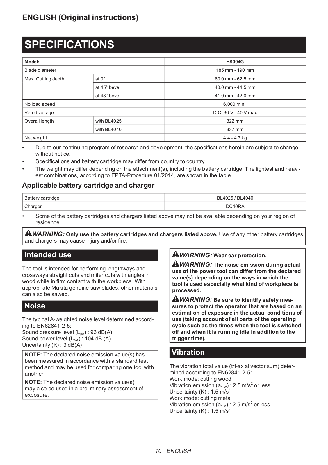
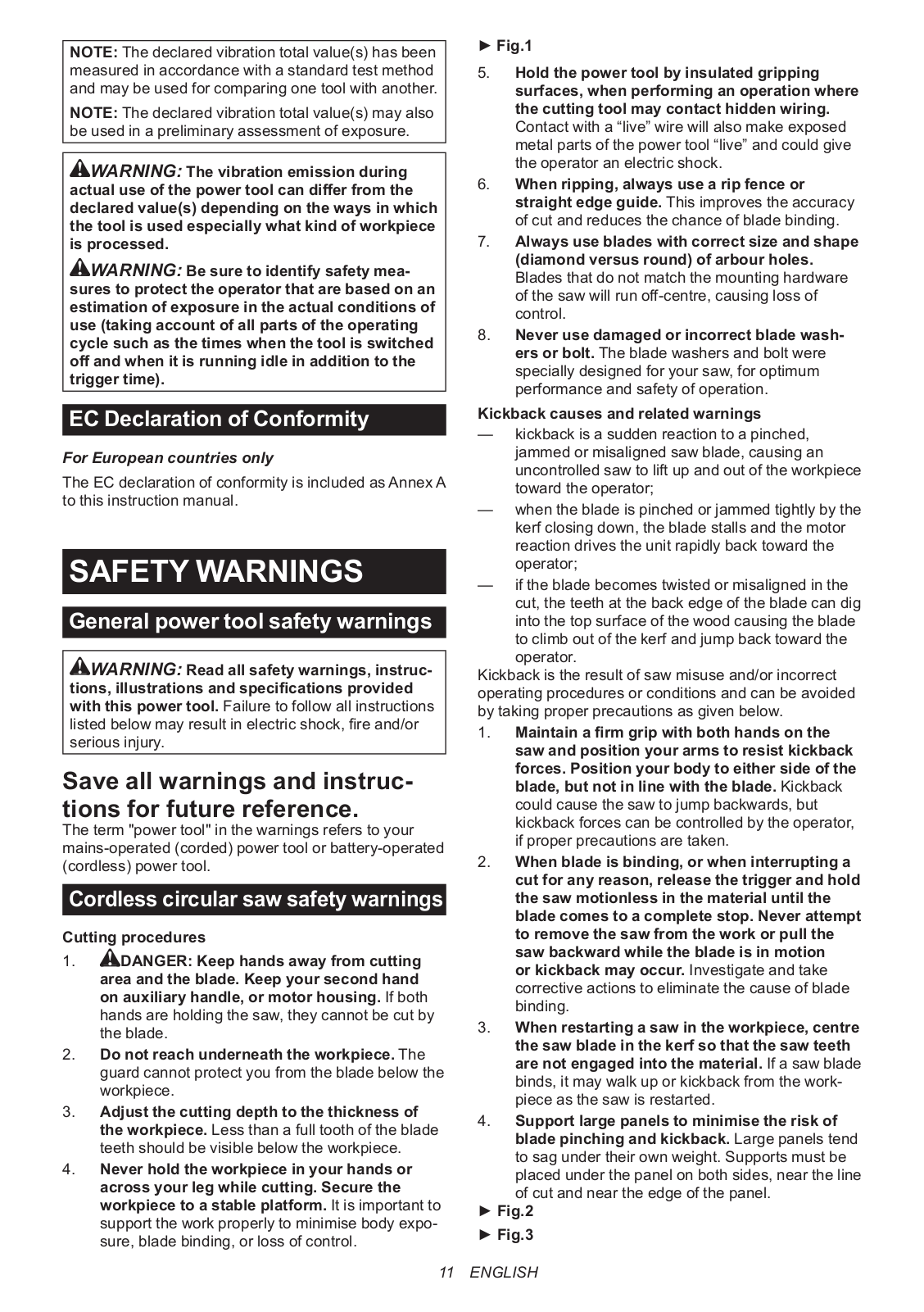
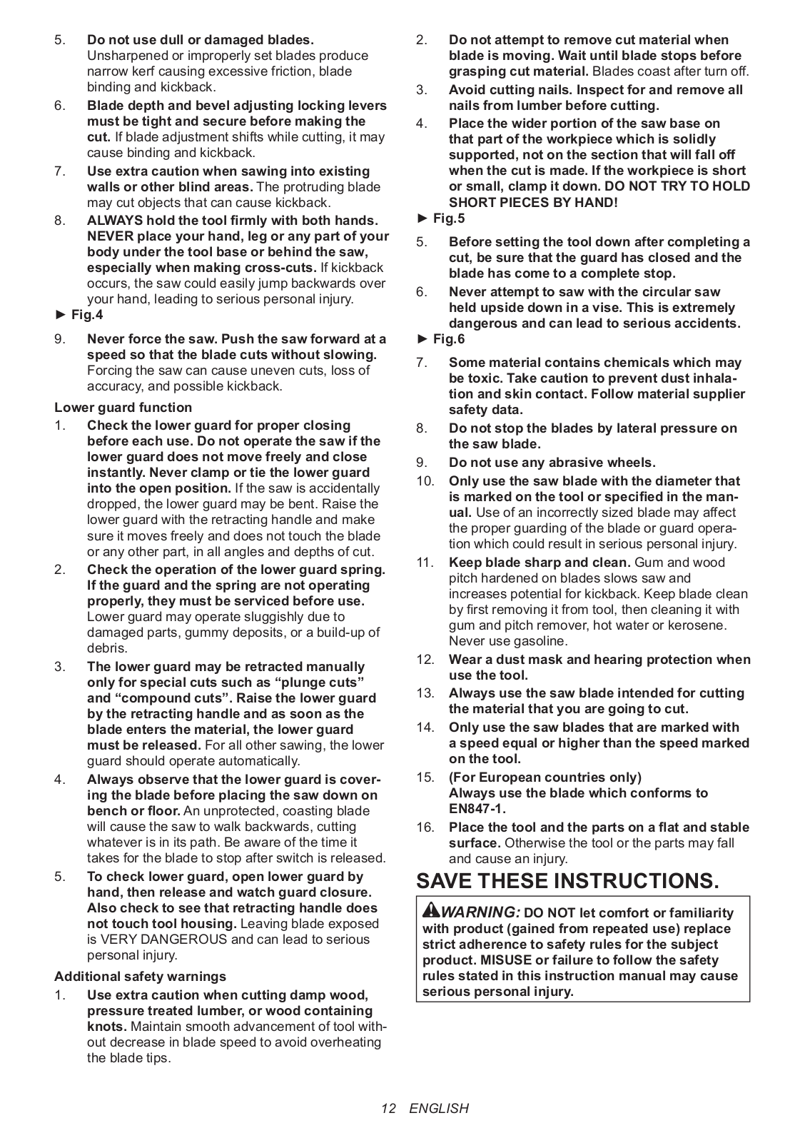
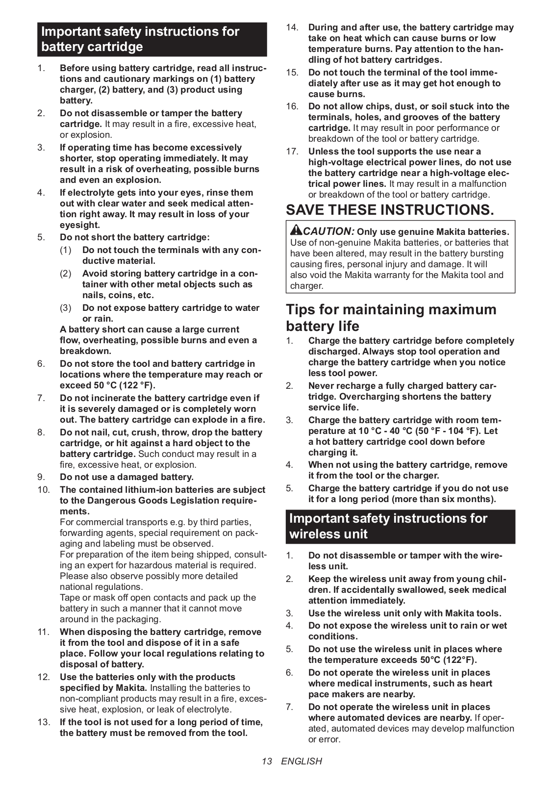
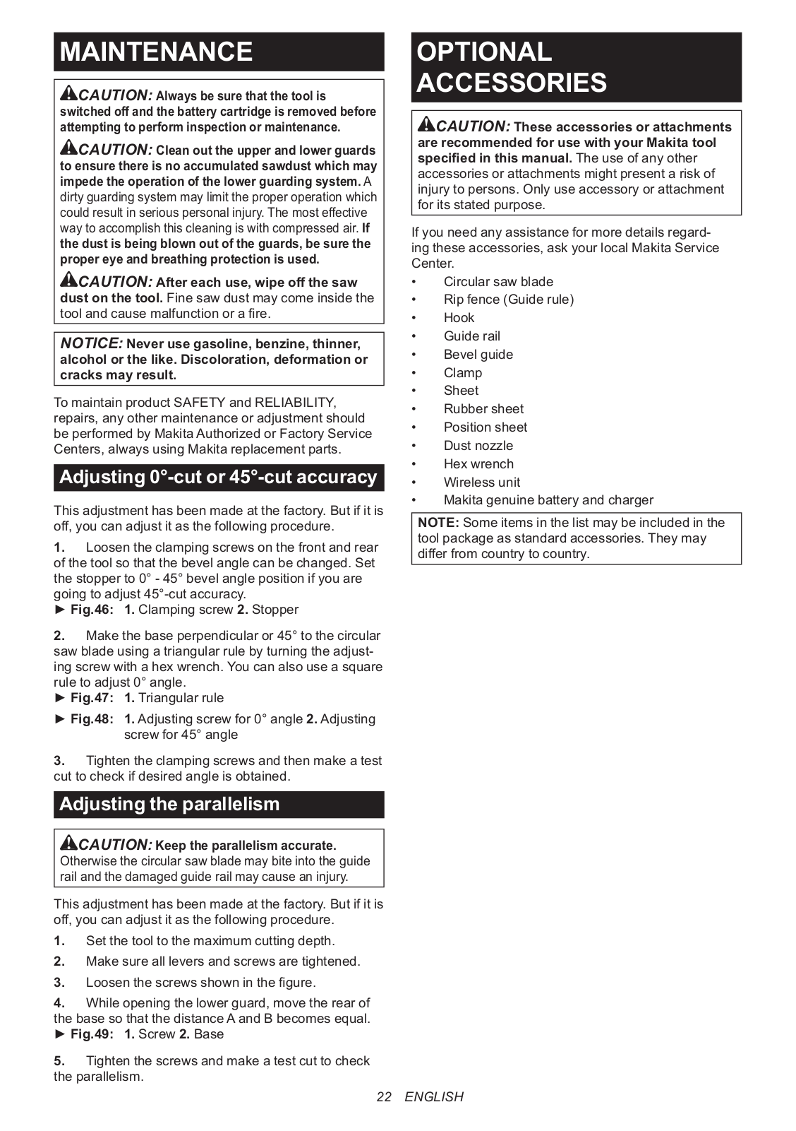
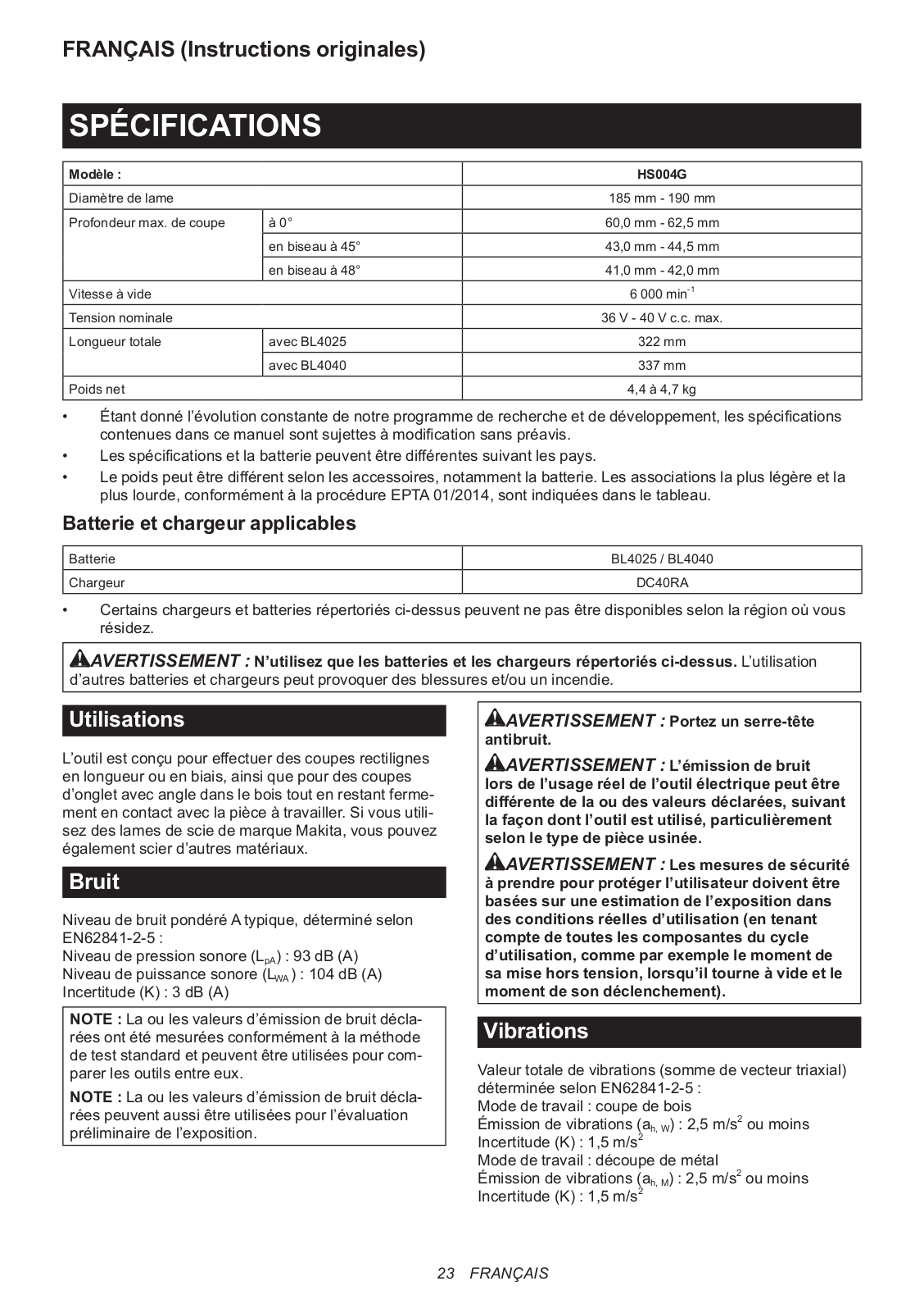
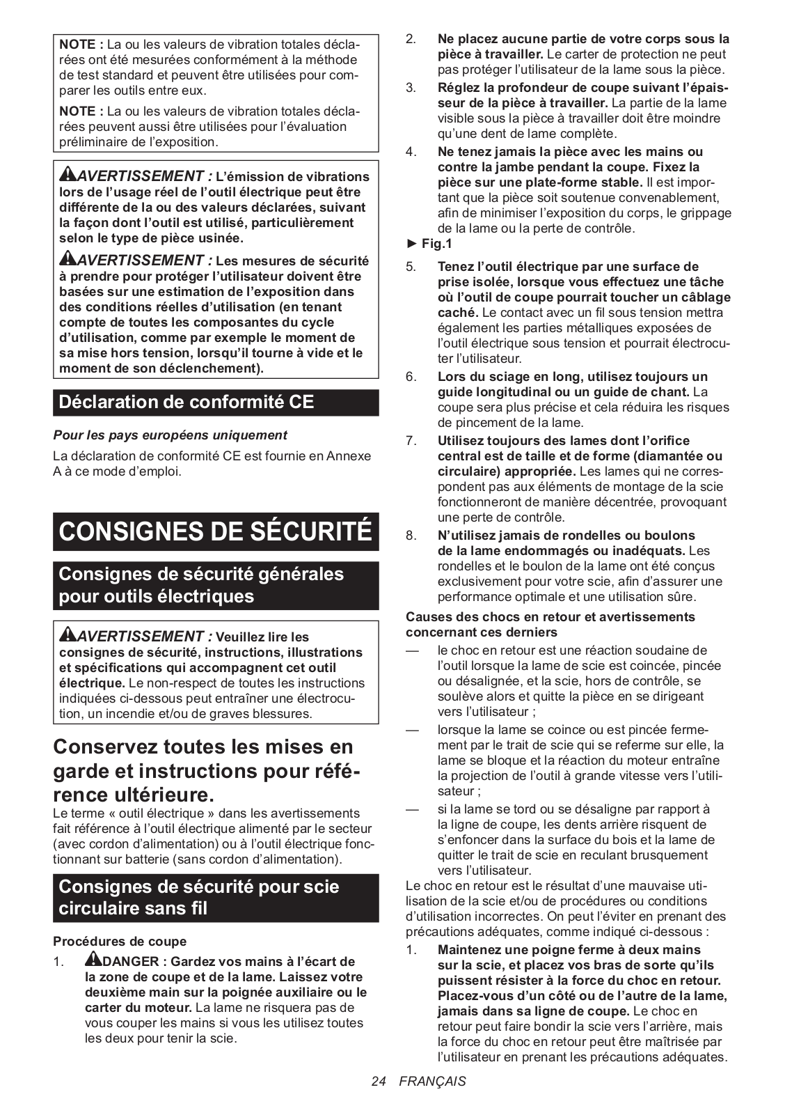
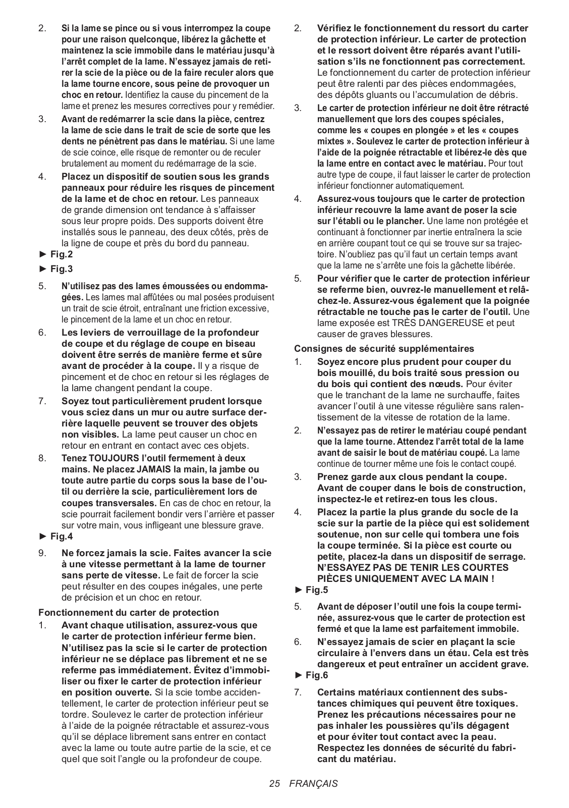
HS004GZ
User Manual
152 pgs
25.59 Mb
0
Service Manual [de]
1 pgs
1.14 Mb
0
Table of contents
Loading...
Makita HS004GZ User Manual
...
Makita User Manual
Download
Specifications and Main Features
Frequently Asked Questions
User Manual
Download
Loading...
+
122
hidden pages
Unhide
You need points to download manuals.
1 point = 1 manual.
You can buy points or you can get point for every manual you upload.
Buy points
Upload your manuals
 Loading...