

Page 1
Optional accessories
Nylon cutting head, Charger DC36WA/DC36RA, Battery BL3622A/BL3626, Battery converter BCV02
Standard equipment
Note: The standard equipment for the tool shown above may vary by country.
Nylon cutting head (Bump & Feed 4)..... 1
Hex wrench (for M4) .............................. 1
Socket wrench ........................................ 1
Pin 4 (Lock key) ..................................... 1
Models No.
Description
CONCEPT AND MAIN APPLICATIONS
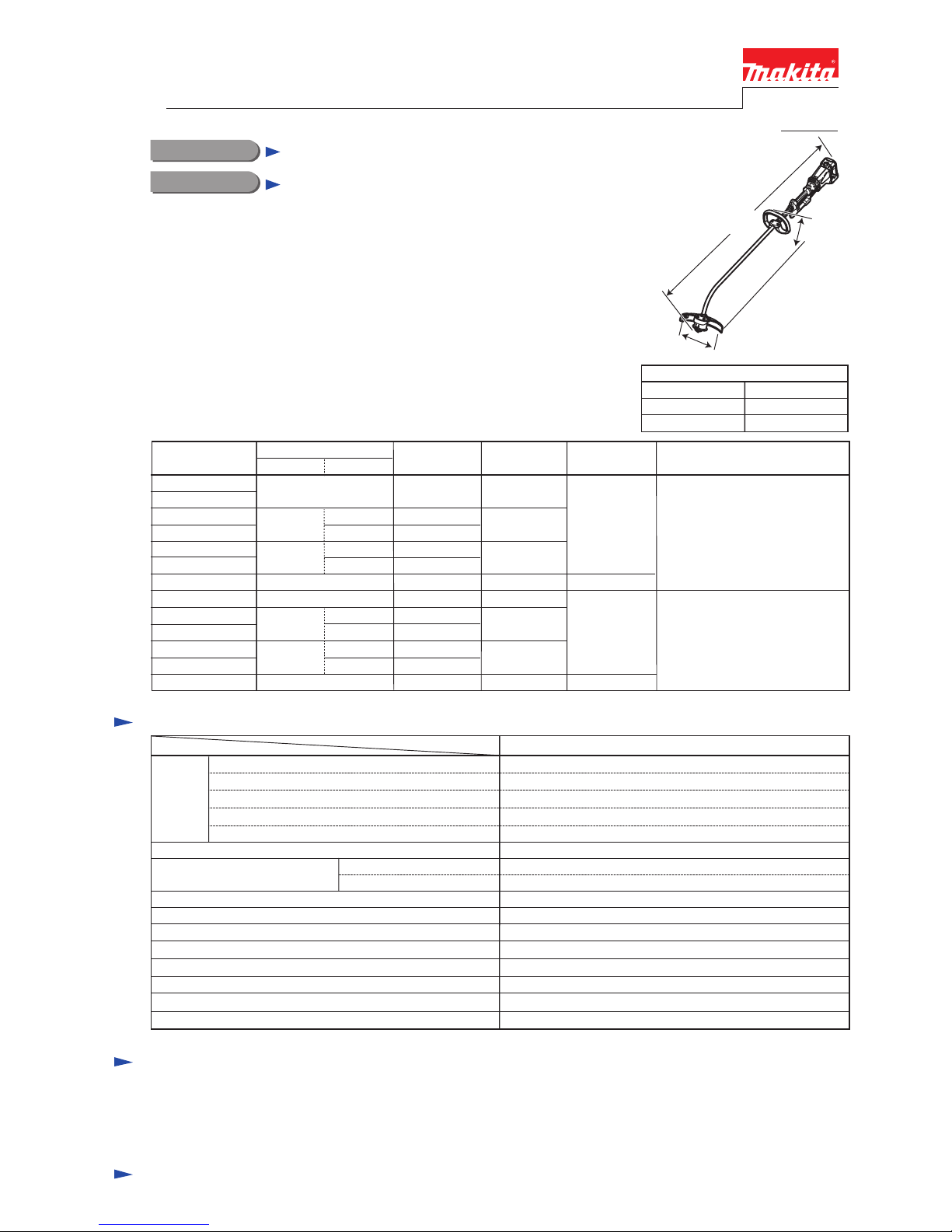
BUR360 (HRU01*1), UR360D
Cordless String Trimmer 300mm (11-3/4
")
Models BUR360 is a cordless string trimmer 300mm(11-3/4") with a bent shaft,
powered by 36V/2.6Ah Li-ion battery BL3626, and charged by DC36RA.
The main advantages are "Environment-friendly" and "Light weight and
compact size" obtained by using Zero exhaust emission Li-ion battery and
Brushless DC motor as the power unit instead of gasoline and engine.
Other advantages are:
• Grass clipping removal function
• High/Low 2-speed selection with variable speed in each range
Model BUR360 is available in the following variations, like UR360D.
Specification
80/ 94
300
36
Standard cutting tool/ Spindle thread size
Battery
Max output: W
Voltage: V
2.2/ 2.6Capacity: Ah
Li-ion
Specifications
Model
Cell
Electric brake Yes
Overload protection Current limiter
*
1 No load speed of the cutting tool *2 with Nylon cutting head
Nylon cutting head/ M8 Right-handed
BUR360
5.1 (11.2)
No load speed*
1: min.-1 = rpm
60(with DC36WA) / 22(with DC36RA)Charging time (approx.): min.
Energy capacity: Wh
High
Low
0 - 7,000
0 - 5,100
Model No. Offered to
type quantity
Charger
Battery
converter
Battery
Battery
cover
BUR360Z
UR360DZ
BUR360RD
BUR360RDE
UR360DWB
UR360DWBE
BUR360ZX2C
HRU01Z
HRU011
HRU01
HRU01C1
HRU01C
HRU01ZX2
No
1
BL3626
BL3622A
BL3622A
2
1
2
No
No
No
No
No
No
No
No
No
No NoNo
1
1
DC36RA
DC36WA
1
2
No
1
DC36WA
No
No
No
BCV02
BCV02
All countries except North and
Central American countries
The models also includes the accessories listed below in "Standard equipment".
1
BL3626
2
No
1
DC36RA
Variable speed control Yes
Soft start Yes
Reversing switch Yes
L
295 (11-5/8)Width (W)
Height (H)
Dimensions: mm (")
Length (L)
420 (16-1/2)
1,720 (67-3/4)
W
H
*
1 Model number for North and Central American countries
North and Central
American countries
Weight according to EPTA-Procedure 01/2003: kg (lbs)*2
Cutting width: mm (") 300 (11-3/4)
PRODUCT
T
ECHNICAL INFORMATION
Accessory bag ........................... 1
Hex wrench (for M5) ................ 1
BCV02 (Battery converter) ....... 1 (for model BUR360ZX2C and
HRU01ZX2 only)
P 1/ 13
Page 2
Repair
[1] NECESSARY REPAIRING TOOLS
CAUTION: Repair the machine in accordance with “Instruction manual” or “Safety instructions”.
Code No. Description Use for
1R036 Bearing setting plate 17.2
1R232 Pipe 30
1R285 Round bar for arbor 11-50
holding Ball bearing 6001ZZ when removing Spindle hub
1R130 Nose 10-30
1R089 Bearing extractor
removing Ball bearing 6901ZZ left in Gear box
holding Helical gear 33, when removing Spindle hub
removing Spindle hub
1R286 Round bar for arbor 12-50 removing Ball bearing 608DDW from Head case
1R350 Ring 60 supporting Motor housing set when assembling Motor section
1R308 Spring pin extractor 4.0 locking Cutter holder when loosening Cutter holder
[2] LUBRICATION
Apply Makita grease N. No.2 to the following portions designated with the black triangle to protect
parts and product from unusual abrasion.
Fig. 1
Item No. Description
Bent pipe complete a little
Gear box 3 g.
Square portion of Flexible shaft
O ring 22
a little
Whole portion
Gear room where Helical gear 33 engages with Armature’s gear
AmountPortion to lubricate
Armature
74
Helical gear 33 Spindle hub
31
31
74
87
87
74 viewed
from 31 side
P 2/ 13
Page 3
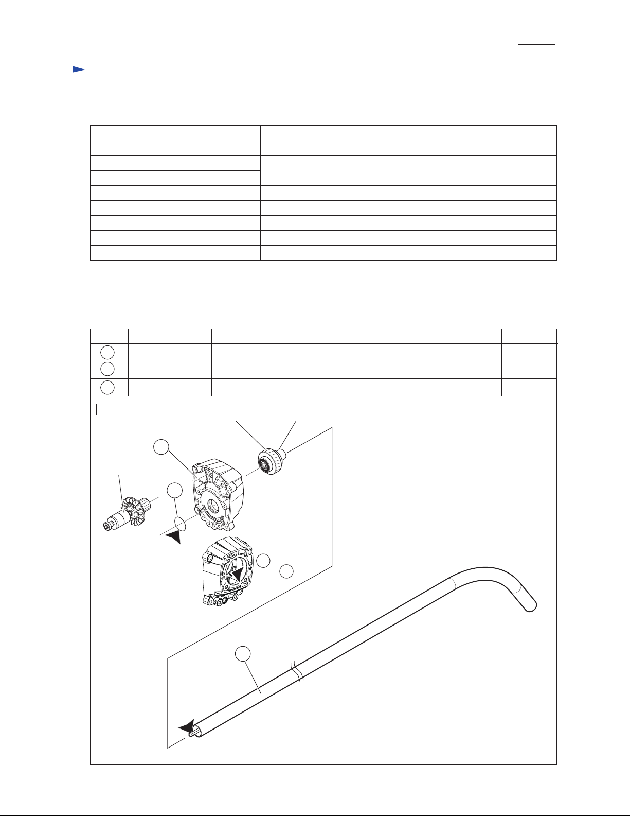
[3] DISASSEMBLY/ASSEMBLY
[3] -1. Bent pipe complete
DISASSEMBLING
Disassemble Bent pipe complete as drawn in Fig. 2.
Fig. 2
1. While inserting 1R308 into the hole of
Cutter holder to stop Cutter shaft revolving,
turn Cutter assembly counterclockwise by
hand. Cutter assembly is removed from
Cutter shaft.
2. Loosen two M6x30 Hex socket
head bolts and remove Protector
cover and Protector.
Note: The M6x30 Hex socket
head bolts have Spring
washer 6 on each thread
to prevent losing.
It is not necessary to
separate them from
Protector.
Remove M5x10 Hex socket
head bolt and Protector clamp
from Head case complete, and
then Remove Head case complete
from Bent pipe complete by
loosening M5x25 Hex socket
head bolt.
M6x30 Hex socket
head bolt (2 pcs.)
M5x10 Hex
socket head bolt
Protector
clamp
Protector
Protector
cover
Cutter
assembly
male thread of Cutter shaft
(connected with Cutter
assembly at its inside)
1R308
M5x25 Hex
socket head bolt
Head case
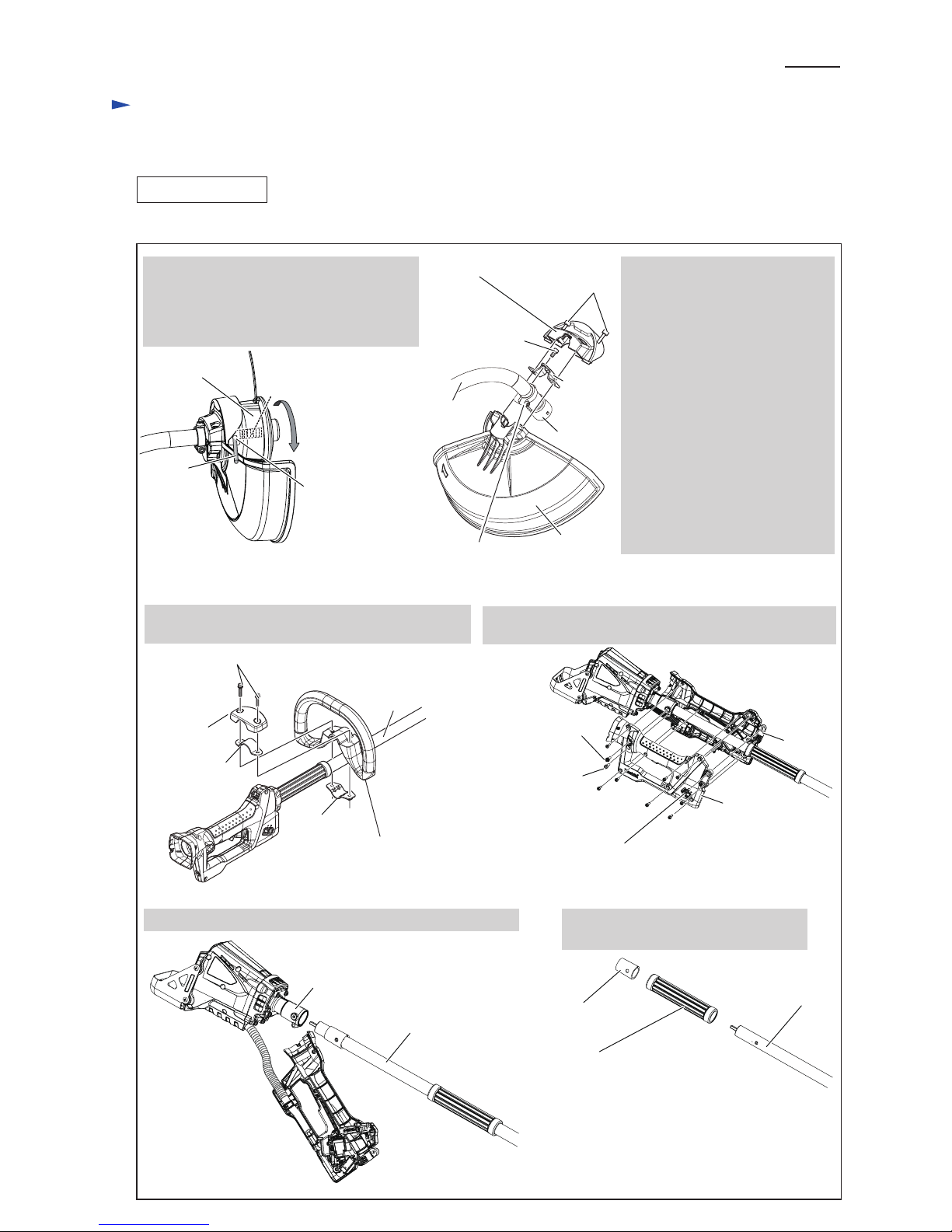
3. Remove two M5x25 Hex socket head bolts and
separate Loop handle set* from Bent pipe complete.
4. Unscrew the following screws and bolts (11 pcs. in total),
and separate Grip R from Grip L.
*M5x25 Hex socket head bolt (2 pcs.)
*mark: The components of Loop handle set
*Clamp
cover B
*Clamp 33
M5x20 Pan
head screw
Grip R
M5x20 Hex
socket head bolt
M5x18 Hex
socket head bolt
4x18 Tapping
screws (8 pcs.)
Grip L
5. Pull off Bent shaft pipe complete from Pipe bracket by hand.
6. Pull off Pipe rubber and Spacer from
Bent pipe complete.
Pipe bracket
Bent pipe
complete
Spacer
Note: Some specifications
have no Spacer.
Pipe rubber
Bent pipe
complete
Repair
P 3/ 13
hole of Cutter
holder for 1R308
Bent pipe
complete
Bent pipe
complete
*Clamp 24
*Loop handle
Page 4
[3] DISASSEMBLY/ASSEMBLY
[3] -1. Bent pipe complete (cont.)
[3] -2. Head case complete
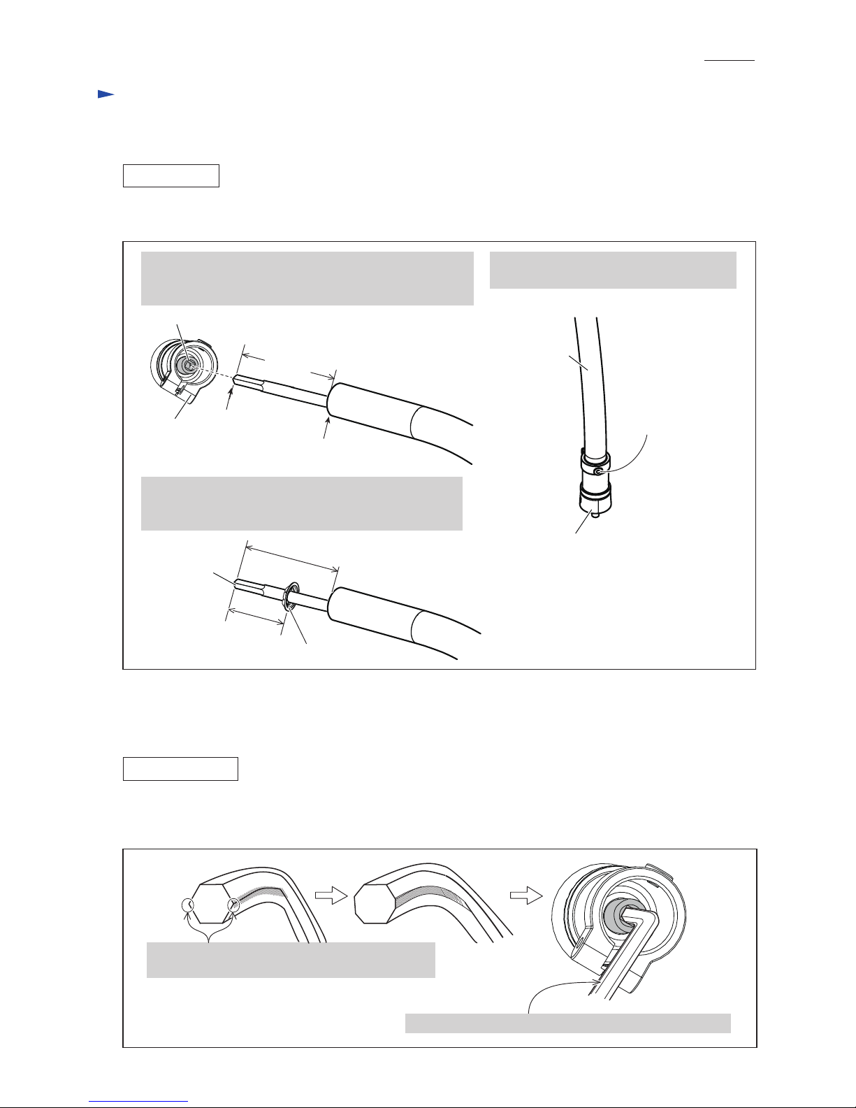
ASSEMBLING
(1) Assemble Head case complete to Bent shaft pipe complete as drawn in Fig. 3.
(2) Assemble Loop hand set, Protector section, and Cutter assembly to Bent pipe complete in the reverse order of
Disassembly. Refer to Fig. 2.
Fig. 3
1. Pull out Flexible shaft to 100mm long from Bent shaft end.
Insert the square tip of Flexible shaft into the square hole
of Cutter shaft while turning.
1A. When replacing Flexible shaft with the new one,
place Bearing washer to the position that is 43 mm far
from the tip of Flexible shaft after step 1 shown above.
2. Align the hole of Head case complete with
the hole of Bend pipe complete.
The holes of Head case
complete and Bend pipe
complete for M5x10
Hex socket head bolt.
(1) Remove Head case complete from Bent pipe complete as Fig. 2.
(2) Remodel Hex wrench 5 as drawn in Fig. 4 to fit to the square hole of Cutter shaft.
DISASSEMBLING
1. File off the two edges in order to fit Hex wrench 5
to the square hole of Cutter shaft.
Fig. 4
Head case
complete
Square hole of Cutter shaft
Bearing washer
100 mm
Bent shaft end
Head case
complete
Bend pipe
complete
100 mm
43 mm
Flexible shaft
(new)
Repair
P 4/ 13
Square tip of
Flexible shaft
2. Hex wrench 5 can be fit to the square hole of Cutter shaft.
Page 5

Cutter holder
Modified Hex wrench 5 (See previous page.)
1R308
[3] DISASSEMBLY/ASSEMBLY
[3] -2. Head case complete (cont.)
(3) Disassemble Head case complete as drawn in Fig. 5.
Assemble Head case complete in the reverse order of Disassembly. Refer to Fig. 5.
Be careful to the directions of Washer and Bearing washer. (Fig. 6)
Fig. 5
1. Lock Cutter holder with 1R308 inserted into its hole.
Hold Head case complete with vise.
Insert the modified end of Hex wrench 5 to the square
hole of Cutter shaft.
Cutter holder is removed from Head case complete by
turning Hex wrench 5 counterclockwise.
2. Put Head case complete on Turn table of
Arbor press. Press Cutter shaft with 1R286.
Cutter shaft section is separated from
Head case complete.
3. Disassemble Cutter shaft section as drawn below.
DISASSEMBLING
ASSEMBLING
Cutter holder
Cutter shaft
section
1R286
Cutter shaft
Cutter shaft
Bearing washer
Head case
complete
Head case
complete
Head case complete
Head case
Ball bearing 608ZZ Ball bearing 608DDW
Collar Washer Spring washer M8
Bearing washer
Washer
Spring washer 8
Ball bearing 608ZZ
Ball bearing 608DDW
Cutter shaft
Collar
Cutter holder
Fig. 6
Repair
P 5/ 13
Face the projection of Washer and Bearing washer to the opposite direction of Cutter holder.
Page 6

[3] DISASSEMBLY/ASSEMBLY
[3] -3. Helical gear 33, Spindle hub
(1) Disassemble Bent pipe complete from Pipe bracket as drawn in Fig. 2.
And then, remove Helical gear section as drawn in Fig. 7.
Fig. 7
DISASSEMBLING
ASSEMBLING
1. Remove Gear box cover, and
then remove four M5x20 Pan
head screws and Pipe bracket.
2. Remove Helical gear section
from Gear box.
Fig. 8
(2) Disassemble Helical gear section as drawn in Fig. 8.
1R285
1R285
1R036
1. Put Helical gear 33 on 1R232, and press Spindle hub with 1R285.
Ball bearing 6901ZZ, Flat washer 12 and Helical gear 33 are separated from Spindle hub.
2. Put Ball bearing 6901ZZ on 1R036,
and press Spindle hub with 1R285.
Ball bearing 6901ZZ is separated
from Spindle hub.
Spindle hub
Spindle hub with
Ball bearing 6001ZZ
Spindle hub
1R232
Ball bearing
6901ZZ
Ball bearing
6001ZZ
Ball bearing
6001ZZ
Ball bearing
6901ZZ
Helical gear 33
Helical gear 33
Flat washer 12
Flat washer 12
Gear box
cover
Pipe bracket
M5x20
Pan head
screw
(4 pcs.)
Helical
gear section
2A. If Ball bearing 6901ZZ is left in Gear box,
remove it using 1R089 and 1R130 as
drawn below.
1R089
1R130
Ball bearing 6901ZZ
Ball bearing 6901ZZ
Repair
P 6/ 13
Helical
gear
section
Assemble Helical gear section in the reverse order of Disassembly.
Note: Be sure to set two Flat washers 12 in place as drawn in Fig. 8.
Page 7

[3] DISASSEMBLY/ASSEMBLY
[3] -4. Rotor, Stator
DISASSEMBLING
(1) Separate Housing R from Housing L as drawn in Fig. 10.
Fig. 10
1. Unscrew the following screws and bolts, and separate Grip R from Grip L.
* M5x20 Hex socket head bolt * M5x16 Hex socket head bolt
* 4x18 Tapping screw (8 pcs.) * M5x20 Pan head screw
And then, pull off Shaft pipe B complete from Pipe bracket.
M5x20 Hex socket
head bolt
M5x20 Pan head screw
M5x16 Hex socket
head bolt
4x18 Tapping screw
( 8 pcs.)
Grip R
Grip L
Shaft pipe B complete
Pipe bracket
2. Remove Gear box cover from Gear box. 3. Remove four 5x25 Tapping screws.
Gear case cover
Gear box
4. Remove four M4x12 + screw and
Battery guard from Housing set.
5. Remove five 4x18 Tapping screws
and Housing R from Housing L.
Housing R
Battery guard
Repair
P 7/ 13
4x18 Tapping
screw (5 pcs.)
5x25 Tapping
screw (4 pcs.)
M4x12 + screw
(4 pcs.)
Page 8

P 8/ 13
[3] DISASSEMBLY/ASSEMBLY
[3] -4. Rotor, Stator (cont.)
DISASSEMBLING
(2) Remove Motor section as drawn in Fig. 11.
(3) Remove Rotor from Stator as drawn in Fig. 12.
Fig. 11
2. Unscrew four 4x18 Tapping
screws, and separate Gear
box from DC motor section.
3. Unscrew three 4x18 Tapping screws,
and separate Motor housing R from
Motor housing L.
And then, remove Rotor together
with Stator from Motor housing L.
1. Disconnect the connectors of DC
motor section from those of
Controller, and then remove DC
motor section together with
Gear box from Housing L.
Motor housing R
DC motor
section
Workbench
Gear box
4x18 Tapping screw
(4 pcs.)
4x18 Tapping
screw (3 pcs.)
Motor housing L
RotorStator
4. Put Motor section on a workbench so that reverse side of the drive end of Rotor touches workbench.
Then, separate Rotor from Stator by pressing Stator down towards workbench while pulling up Rotor.
Fig. 12
Caution for Handling of Rotor
When handling or storing multiple Rotors, be sure to provide enough
distance so that they do not draw each other.
Rotor is a strongly magnetic body.
Therefore, failure to follow this instruction could result in:
* Finger injury caused by pinching between Rotors pulling each other
* Magnetic loss of Rotors
enough
distance
Repair
DC motor
section
Gear box
Housing L
Page 9

P 9/ 13
Repair
[3] DISASSEMBLY/ASSEMBLY
[3] -4. Rotor, Stator (cont.)
Fig. 13
Fig. 14
ASSEMBLING
Assemble Rotor and Stator in the reverse order of disassembly. Refer to Figs. 12, 11, and 10.
Note 1: Rotor dragged by strong magnet force may bump on Circuit plate of Stator and give damage on that plate.
Therefore, assemble Rotor as drawn in Fig. 13.
Note 2: The mating face of Motor housing L tends to deviate from that of Motor housing R when assembling.
Therefore, assemble Motor housing L and Motor housing R as drawn in Fig. 14 after setting Rotor and
Stator to Motor housing L.
Circuit plate
Worktable
1. Hold Rotor perpendicularly.
3. When Rotor’s ball bearing reaches
the surface of Worktable through
the shaft hole, move Stator slowly
toward Rotor fan.
2. Pass Rotor held in perpendicular
slowly through Stator, aiming
precisely at the shaft hole of
Circuit plate.
1. After mounting Rotor and
Stator to Motor housing L,
set Motor housing R to
Motor housing L.
2. Closely applying the drive end
(Gear side) to 1R350, stand
Motor housing set on 1R350.
3. The mating face of Motor housing R is
automatically aligned to that of Motor
housing L on 1R350.
And tighten three 4x18 Tapping screws.
1R350
Motor
housing set
4x18 Tapping screw
(3 pcs.)
Motor
housing L
Motor
housing R
Page 10

[3] DISASSEMBLY/ASSEMBLY
[3] -5. Indicator
[3] -6. Link plate
DISASSEMBLING
ASSEMBLING
ASSEMBLING
Fig. 15
Fig. 16
(1) Separate Grip R from Grip L, as per the center two illustrations in Fig. 2.
(2) Remove Indicator as drawn in Fig. 15.
(1) Assemble Indicator to Grip L.
(2) Set Steel ball 5.0 to Grip L.
(3) Mount Compression spring 2.
While holding both Steel ball 5.0 and Compression spring 2,
remove Indicator from Grip L.
Lock off button
Link plate
Link plate
holder
Fit this projection to Link plate
holder on Grip L.
Fit this prong portion to
the projection of Switch.
Fit this prong portion to the
projection of Lock off button.
Assemble Link plate as drawn in Fig. 16
Switch
Repair
P 10/ 13
Indicator
Steel ball 5.0
Compression
spring 2
Grip L
Page 11

P 11/ 13
Circuit diagram
White
Orange
Blue
Brown
Yellow
Main switch
Reverse
switch
Controller
Stator
Fig. D-1
3-pin
Connector
5-pin
Connector
6-pin
Connector
6-pin
Connector
For North American countries
Color index of lead wires' sheath
Black
Red
Terminal
AS
Terminal
Fuse
AS
Fuse is connected between Controller
and (+) pole of Terminal.
Power supply
cord unit
Page 12

P 12/ 13
Wiring diagram
Putting Power supply cord unit
Putting Connectors
Fig. D-3
Fig. D-2
Tube
Cord clamp
Cord clamp
Power supply cord unit
Face the tube of Power supply cord unit to Housing L, and set Power supply cord unit
in place as drawn below.
Housing L
Grip
Do not put any Lead wires
between Terminal and Rib B.
Rib B
Terminal
Cord clamp
5-pin connector
6-pin connector
Tube
Power supply
cord unit
Rib A
Power supply cord has to be fastened with
Cord clamp so that the cord end aligns to Rib A.
Do not clamp Tube with Cord clamp.
Power
supply
cord
Controller
Stator
Boss
Flag connectors have
to be connected so that
their wire connecting
portion is located to
the opposite side of
+ - pole marks.
Route Stator’s Lead wires
between Controller and Boss.
3-pin connector
Room for
5-pin connector
Fit 3-pin connector into the room on
Housing L as drawn below, and then
put 6-pin connector on 3-pin connector
as drawn in right.
Put Fuse in this place.
(for North American countries.)
Page 13

P 13/ 13
Wiring diagram
Wiring in Grip
Fig. D-4
See Fig. D-5 in details about the setting of
Reverse switch and its Receptacles.
Reverse switch
6-pin connector
Setting Reverse switch and Receptacles
Fig. D-5
Terminal (1)
Grip L
Receptacle covered with Sleeve
Terminal (P)
Reverse switch
Receptacle covered with Sleeve has to be
connected to Terminal (1) of Reverse switch.
Lead wires connected to Terminals
has to be faced to the direction drawn
in left so that they can be easily routed
between Boss and the wall of Grip L.
Receptacle
Boss
Put the slack portion of
lead wires in this place.
Put 6-pin connector into the room of
Grip L as drawn left.
Be careful to the direction.
Reverse switch has to be put to Grip L so
as to face its Terminal (1) to Grip L side.
 Loading...