

Page 1
T
Models No.
Description
ECHNICAL INFORMATION
HR262D/ BHR262, HR262TD/ BHR262T
(HRH01C/
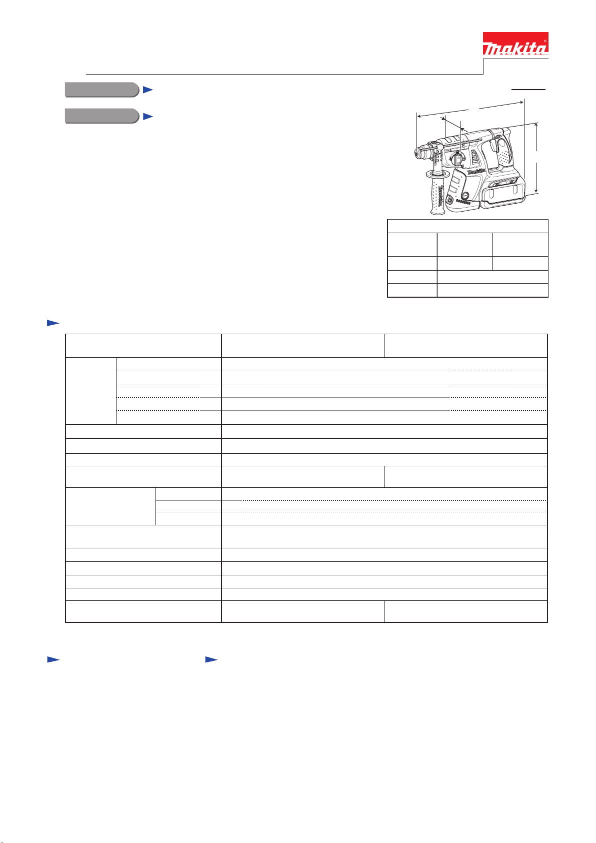
26mm (1") Cordless Combination Hammers
*1 Model numbers for North and Central American countries
HRH01, HRH02C/ HRH02)*1
PRODUCT
P 1/22
L
W
CONCEPT AND MAIN APPLICATIONS
These 36V cordless combination hammers have been developed based on
Models BHR261 and BHR261T, and feature compatibility with both
Makita 36V-2.6Ah Li-ion battery BL3626 and 36V-2.2Ah Li-ion battery
BL3622A.
(Note: BHR261 and BHR261T run on only 36V-2.6Ah battery BL3626.)
Other features are exactly the same as BHR261 and BHR261T as follows:
• 3 operation modes (rotation only/ rotation with hammering/ hammering only)
• Vibration absorbing handle and soft grips
• Good tool-balance due to the center of gravity closer to handle
HR262TD/BHR262T (HRH02/HRH02C*1) are equipped with
quick change chuck.
These new products are available in the variations listed in the next page.
Length (L)
Width (W)
Height (H)
Specification
HR262D/ BHR262
(HRH01C/ HRH01)
Voltage: V
Capacity: Ah
Battery
No load speed: min.ˉ¹ = rpm
Impacts per minute= min.ˉ¹
Max. output (W) 500
Chuck type
Capacity: mm (")
Operation mode
Variable speed control
Reverse switch
Torque limiter
Weight according to
EPTA-Procedure 01/2003*3: kg (lbs)
*2 Round shank bits can also be used by replacing the factory-mounted chuck with Quick change drill chuck (keyless).
*3 with Battery and Side grip
Cell Li-ion
Energy capacity: Wh 80/ 94
Charging Time: min.
Adapted for
SDS-PLUS bits
Concrete
Steel
Wood
(Rotation only/ Rotation with hammering/ Hammering only)
4.5 (9.9)
*1
36
2.2/ 2.6
60 with DC36WA/ 22 with DC36RA
0 - 1,200
0 - 4,800
26 (1)
13 (1/2)
32 (1-1/4)
3 modes
Yes (by trigger)
Yes
Yes
YesLED job light
Dimensions: mm (")
HR262D/
BHR262
363 (14-1/4)
HR262TD/ BHR262T
(HRH02C/ HRH02)*1
Adapted for SDS-PLUS bits
and Round shank bits*
4.8 (10.6)
387 (15-1/4)
104 (4-1/8)
235 (9-1/4)
H
HR262TD/
BHR262T
2
Standard equipment
Grip assembly ........................ 1
Depth gauge (Stopper pole) ... 1
Quick change drill chuck ....... 1
(for HR262TD/BHR262T,
HRH02/HRH02C*
Bit grease ............................... 1
(for some country)
Waste cloth ............................ 1
(for some country)
Note: The standard equipment
for the tool shown above
may vary by country.
1)
Optional accessories
SDS-PLUS bits
Taper shank TCT bits
Taper shank adapter
Cotter
Grip drill
Grip drill holder
Drill chuck assembly
Chuck adapter
Drill chuck S13
Chuck key S13
SDS-Plus hammer chuck set
Scraper assembly
Dust cup 5
Dust cup 9
Dust extractor attachment
Grease vessel 30g
Hose
Joint 25
Bit grease
Plastic carrying case
Depth gauge (Stopper pole)
Blow out bulb
Cold chisels
Keyless drill chuck
Safety goggles
Dust cup
Grooving chisels
Bull points
Scaling chisels
Fast charger DC36RA
Battery BL3626
Charger DC36WA
Battery BL3622A
Battery adapter BAP36N
Battery converter BCV01
Battery converter BCV02
Side grip set
Grip base set
Page 2

Variation list
BHR262/ HR262D
Model No.
BHR262ZC
BHR262Z2C
BHR262RD
BHR262RDE 2 1 No NoYesDC36RA BL3626
BHR262DP1
HR262DZ NoNoNo No
HR262DWB Yes1 No
HR262DWBE 2
BHR262T/ HR262TD
Model No.
BHR262TZ NoNoNo No No
BHR262TRDE Yes2BL3626 1 No
BHR262TDP1 Yes2BL3626 1 BAP36N NoDC36RA
HR262TDZ NoNoNo No No
HR262TDWBE Yes2BL3622A 1 No
Charger
No
DC36RA
No
DC36WA
Charger
No
DC36RA
No
DC36WA
BL3622A
BL3622ADC36WA
Battery
Type Quantity
No NoBHR262Z
No NoNo NoNo
BL3626
Battery
Type Quantity
No
1 No
Battery
cover
No
1
Battery
cover
Plastic
carrying
case
Yes
Yes2 1DC36RA NoBL3626
Yes No
Plastic
carrying
case
Battery
adapter
BAP36N
BAP36NHR262DBP1 2 1BL3622ADC36WA Yes No
Battery
adapter
Battery
converter
No
NoNo NoNo NoNo
No
No No
No No
No
No
BCV01No
BCV02
No
Battery
converter
No
No
No
No
P 2/22
HRH01*
HRH01Z
HRH01ZX2
HRH01 2BL3626 1
HRH01C
HRH02ZX2
HRH02C 2BL3622A 1 Yes
Note: All models also include the accessories listed in "Standard equipment" of page 1.
*1 Model numbers for North and Central American countries
1/ HRR01C*1, HRH02*1/ HRH02C*1
Model No.
Charger
No NoNoNo No
DC36RA
DC36WA
No NoNoNo No
DC36WA
Battery
Type Quantity
Battery
cover
Plastic
carrying
case
Yes
Battery
adapter
Battery
converter
No No
NoNo NoNoNo No
No No
No NoYes2BL3622A 1
No BCV02
NoDC36RA Yes2BL3626 1
No No
BCV02
NoHRH02
Page 3
Repair
CAUTION: Repair the machine in accordance with “Instruction manual” or “Safety instructions”.
[1] NECESSARY REPAIRING TOOLS
DescriptionCode No. Use for
Retaining ring S pliers ST-2N1R003
1R004 Removing Ring spring 29
1R022 or
1R356
1R291 Removing Retaining Ring S-7
Retaining ring S pliers ST-2
Bearing plate (for arbor press)
Bearing setting plate 8.21R032 Assembling Spiral bevel gear 26
Drill chuck extractor1R139 Removing Spiral bevel gear 26
Ring spring setting tool A1R164 Assembling Oil seal 25 to Gear housing complete
Ring spring setting tool B1R165 Assembling Needle bearing complete to Gear housing complete
T-type hex wrench 3-1271R170 Removing two M4x25 hex socket head bolts on Inner support complete
Tip for Retaining ring pliers1R212 Attachment of 1R003
Pipe 301R232 Assembling Oil seal 25 to Gear housing complete
Round bar for arbor 24-1001R249 Removing Ring spring 28
Round bar for arbor 30-1001R252 Removing Oil seal 25 from Gear housing complete
Bearing extractor1R269 Removing Ball bearing 608ZZ from Inner support complete
Round bar for arbor 7-501R281 Removing Ring 8
Retaining ring S and R pliers
Ring spring removing jig1R306 Removing Ring spring 29 from Tool holder complete/ Tool holder guide complete
Piston cylinder318132-2 Assembling Ring spring 28 to Tool holder complete/ Tool holder guide complete
Removing Ring spring 19 from Tool holder complete/ Tool holder guide complete
Removing Retaining ring WR-12 from Armature shaft
Removing Ring spring 29
Assembling Spiral bevel gear 26Bearing setting plate 10.21R033
P 3/22
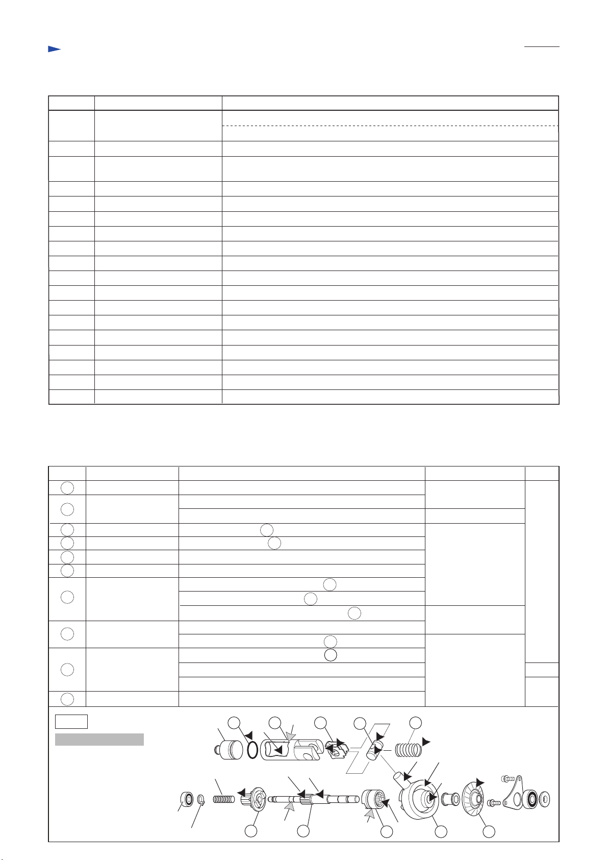
[2] LUBRICATION
Apply the following grease to protect parts and product from unusual abrasion.
* Makita grease RB No.00 to the portions indicated by black triangle
* Molybdenum disulfide lubricant to the portions indicated by gray triangle
Item No. Description Portion to lubricate Lubricant
40
O ring 16
41
Piston cylinder
42
Guide plate Inside that contacts 43 Piston joint
Piston joint Grooves that contact 42 Guide plate
43
44
Compression spring 14 End to be fixed to the boss in Inner housing complete
Spur gear 10 Gear portion that engages with Spur gear 51
48
49 Cam shaft
50
Clutch cam
Swash bearing 10
51
Spiral bevel gear 26 Gear portion that engages with Armature shaft gear
53
Whole surface
(a) Inside where Striker moves
(b) Outside that contacts Tool holder (guide) complete
(c) Gear portion that engages with 50 Clutch cam
(d) Portion to be inserted into 51 Swash bearing 10
(e) Small diameter portion to be inserted into 48 Spur gear 10
(f) Groove for hooking Change plate
(g) Gear portion that engages with 49 Cam shaft
(h) Pole portion to be inserted into 43 Piston joint
(i) Ball bearing portion (See Fig. 3.)
(j) Inside of hole
Makita grease RB No.00
Molybdenum disulfide
Makita grease RB No.00
Molybdenum disulfide
Makita grease RB No.00
Amount
a little
4g
a little
Fig. 1
Transmission parts
Ball bearing
Retaining ring S-7
Striker
Compression spring 7
606ZZ
40 41
48
(a)
(b)
(c) (d)
(e)
49
42 43 44
(f)
50
(g)
(i)
(h)
(j)
51 53
Page 4
Repair
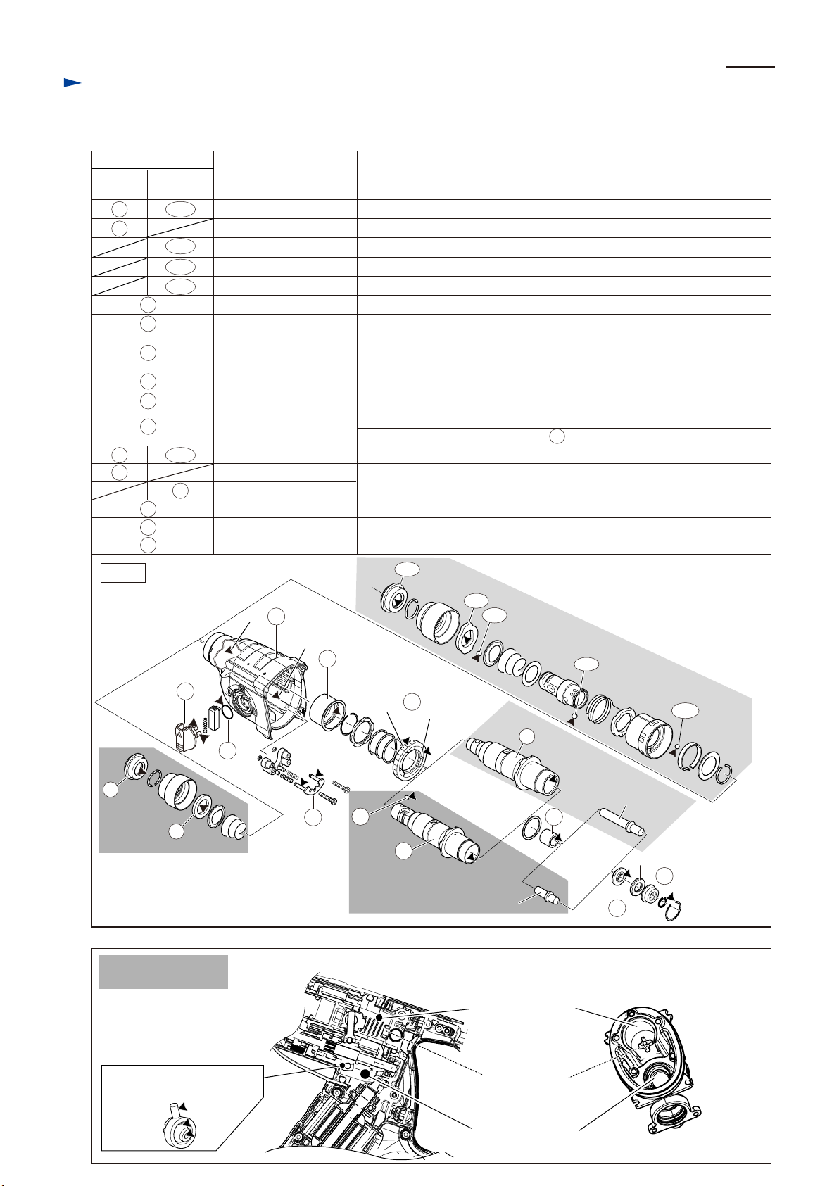
[2] LUBRICATION (cont.)
Apply Makita grease RB No.00 to the following portions indicated by black triangle to protect parts and product
from unusual abrasion.
Item No.
BHR262
HR262D
1
4
29
30
Fig. 2
BHR262T
HR262T
111
114
120 Steel Ball 6 (2 pcs.) Entire surface
124 Steel Ball 5 Entire surface
16
17
28
115
30
Description Portion to lubricate
Cap 35
Ring 21
Stopper
Change lever13
O ring 17
Gear housing complete
Lip portion where Bit is to be inserted
Inner periphery
Inner periphery
Pins
Entire surface
(a) Oil seal 25 on the inside of Gear housing complete
(b) Inside where Swash bearing section rotates (See Fig. 3.)
Needle bearing complete19 Needle bearing portion in Cup washer (See Fig. 37.)
Lock plate complete23 Pins
Spur gear 51
Steel ball 7
Tool holder complete
Tool holder guide complete
(c) Gear portion
(d) Surface where Clutch portion of 30 Tool holder (guide) complete contacts
Entire surface
Inside where Piston cylinder reciprocates
Sleeve 932 Inside where Impact bolt reciprocates
Ring 1034 Portion that contacts Cushion ring 13
O ring 937
Entire surface
111
P 4/22
13
1
BHR262
4
HR262D
Fig. 3
Lubrication Around
Swash bearing 10
(a)
17
(b)
19
28
(c)
16
23
29
30
BHR262
HR262D
[Cross section around Swash bearing 10]
(d)
114
115
BHR262T
HR262TD
30
Impact bolt
Crank section: 5g
120
124
BHR262T
HR262TD
Impact bolt
32
Cushion ring 13
37
34
[Inside view of Inner housing]
Swash bearing section: 4g
(See Fig. 1.)
boss for fixing
Compression
spring 14
Gear section: 17g
Page 5
Repair
[3] DISASSEMBLY/ASSEMBLY
[3] -1. Bit holder section for BHR262, HR262D
Holder section for Drill chuck of BHR262T, HR262TD
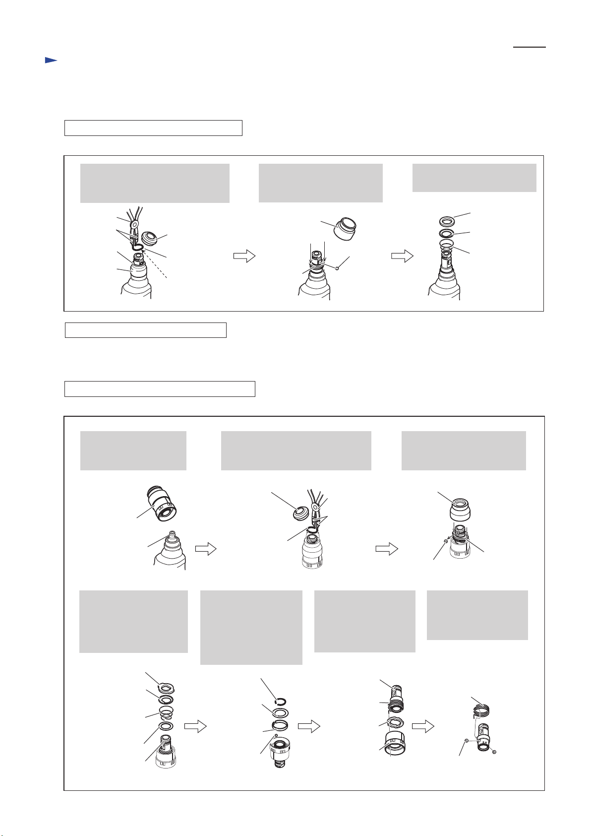
DISASSEMBLING for BHR262, HR262D
Fig. 4
P 5/22
Remove Cap 35 with slotted screwdriver, then remove Ring spring 19
using 1R003 with 1R212.
1R003
1R212
Ring 21
Chuck
cover
ASSEMBLING for BHR262, HR262D
Take the disassembling step in reverse.
Note: Be sure to place the flat portion of Ring spring 19 on Steel ball 7.0. (Fig. 4)
DISASSEMBLING for BHR262T, HR262TD
Fig. 5
Separate Tool holder set
from Tool holder guide
complete.
Cap 35
Ring spring 19
flat portion
Remove Cap 35 with slotted screwdriver, then remove Ring spring 19
using 1R003 with 1R212.
Separate Chuck cover.
Then remove Steel ball 7.0
while pressing down Ring 21.
Chuck cover
Steel ball 7.0
Ring 21
Bit holder section can be
disassembled as drawn above.
Ring 21
Guide washer
Conical
compression
spring 21-29
Separate Chuck cover. Then
remove Steel ball 7.0 while
pressing down Stopper.
Tool holder set
Tool holder guide
Stopper, Guide washer,
Conical compression
spring 21-29, Flat washer
21 can be disassembled
as drawn above.
Stopper
Guide washer
Conical
compression
spring 21-29
Flat washer 21
Tool holder
Cap 35
Ring spring 19
Remove Ring spring 21
with 1R004 from Tool
holder guide side. Flat
washer 24, Leaf spring
and Steel ball 5 can be
disassembled.
Ring spring 21
Flat washer 24
Leaf spring
Steel ball 5
1R003
1R212
Remove Tool holder
together with Change
ring from Change cover.
And separate Change
ring from Tool holder.
Tool holder
Torsion spring 31
Change ring
Change cover
Chuck cover
Stopper
Steel ball 7.0
After removing Torsion
spring 31, Steel ball 6
can be separated from
Tool holder.
Torsion spring 31
Steel ball 6 (2 pcs.)
Page 6
Repair
[3] DISASSEMBLY/ASSEMBLY
[3] -1. Bit holder section for BHR262, HR262D
Holder section for Drill chuck of BHR262T, HR262TD (cont.)
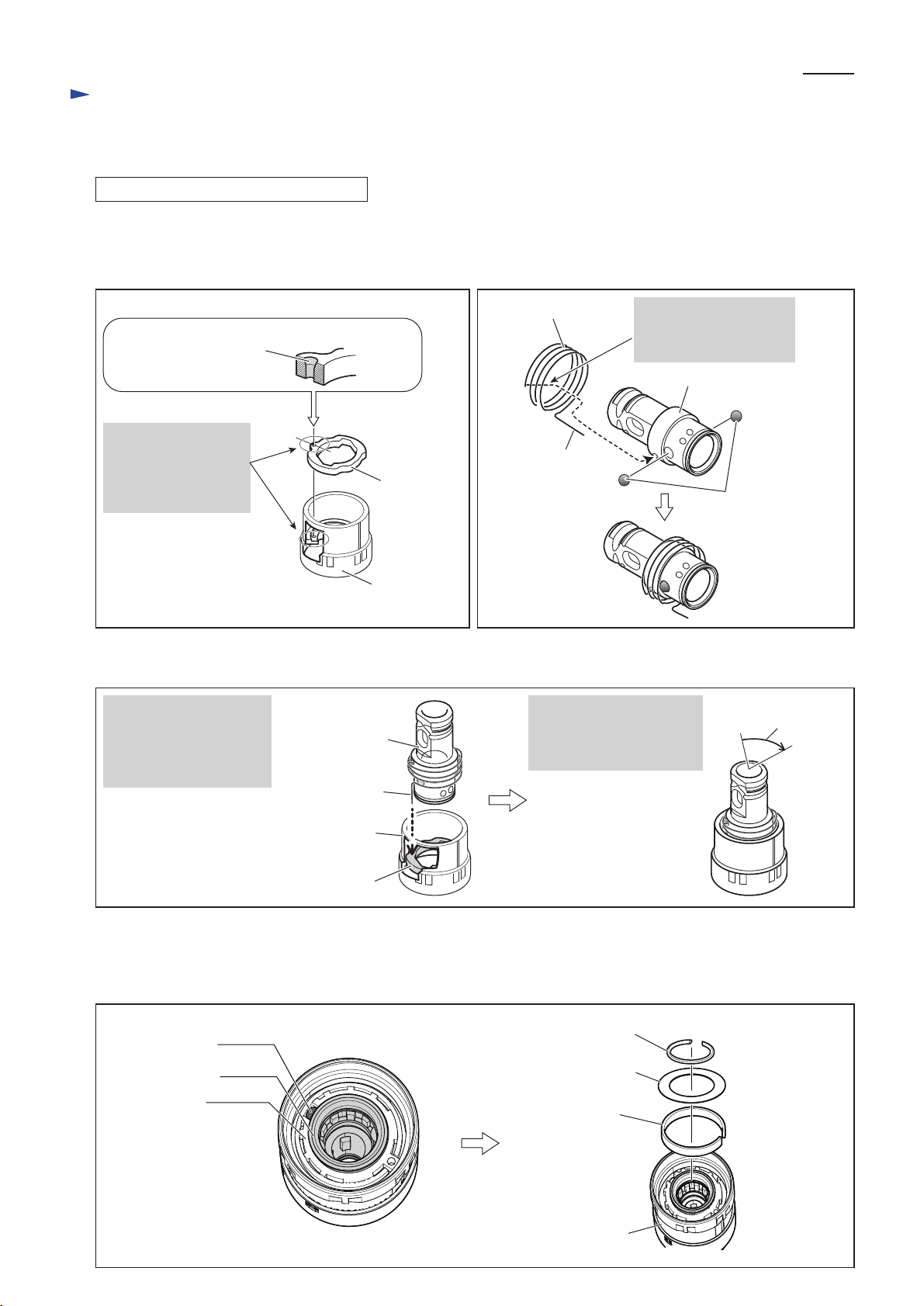
ASSEMBLING for BHR262T, HR262TD
(1) Assemble Change ring to Change cover. (Fig. 6)
(2) Assemble Torsion spring 31 to Tool holder, then mount Steel balls 6 to Tool holder. (Fig. 7)
Note: Apply Makita Grease RB No.00 to Steel balls 6 to prevent them from falling off.
Fig. 6 Fig. 7
P 6/22
Note:
Face the chamfered end
of the hole upward.
Aligning the hole of
Change ring with that
of Change cover,
assemble Change ring
to Change cover.
(3) Assemble Tool holder to Change cover. (Fig. 8)
Fig. 8
Insert the long arm of
Torsion spring 31 into
the hole of Change cover
through the hole of
Change ring.
[Section a - a']
a
a'
Change ring
Change cover
Tool holder
The long arm of
Torsion spring 31
Torsion spring 31
long arm
By turning Tool holder
approx. 75
Tool holder can be
fastened to Change cover.
°
clockwise,
Insert the short arm of
Torsion spring 31 into
the hole of Tool holder.
Tool holder
Steel ball 6 (2pcs.)
75°
Change cover
Change ring
(4) Put Steel ball 5.0 in the groove surrounded by Change cover and Tool holder. (left in Fig. 9)
(5) Set Leaf spring and Flat washer 24 in change cover, then secure them with Ring spring 21. (right in Fig. 9)
(6) As for the assembling of Cap 35 side, do the reverse of disassembling steps. Refer to Fig. 4.
Fig. 9
Steel ball 5.0
Change cover
Tool holder
Ring spring 21
Flat washer 24
Leaf spring
Change cover
Page 7
Repair
[3] DISASSEMBLY/ ASSEMBLY
[3] -2. Drill chuck assembly for BHR262T, HR262TD
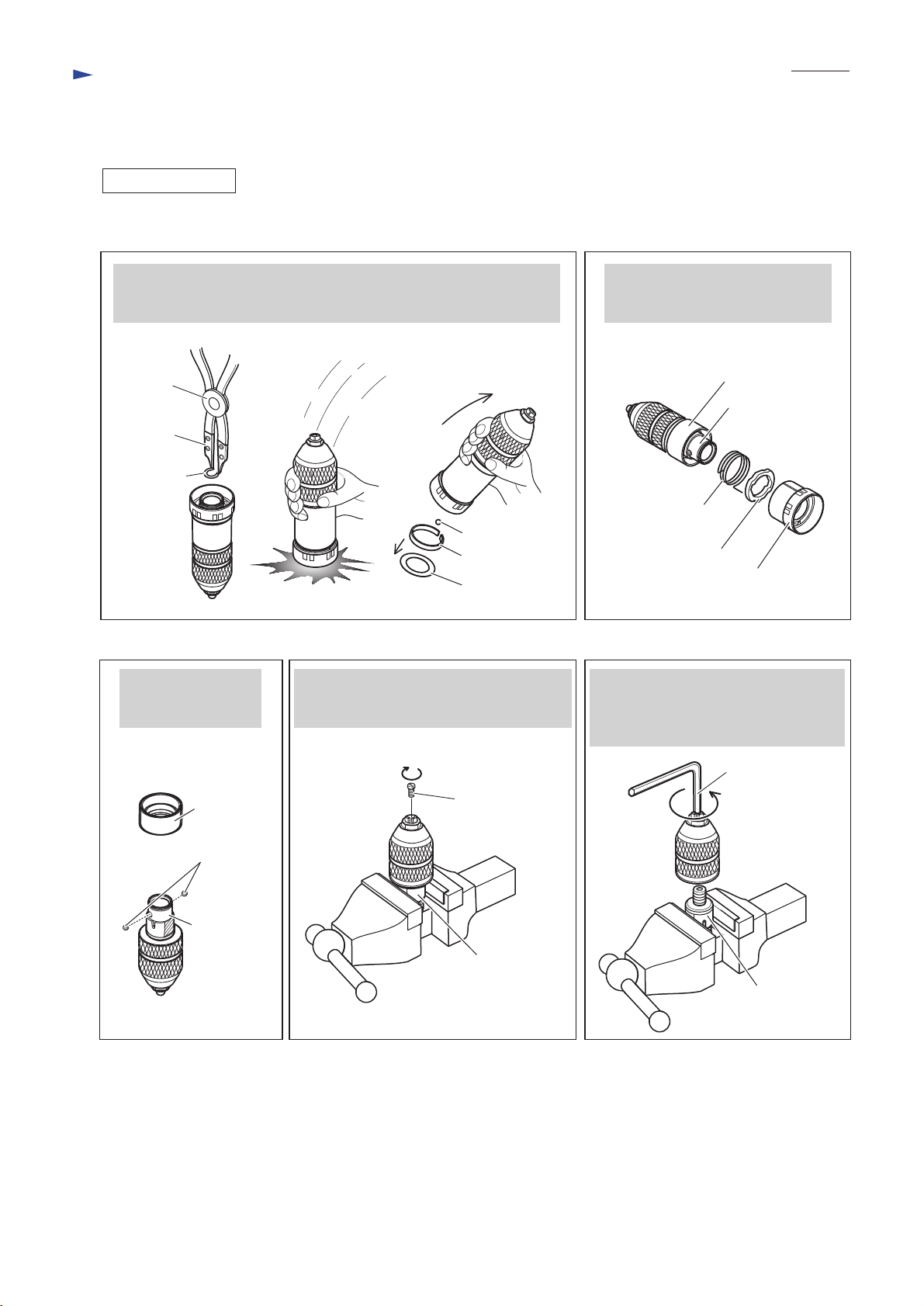
DISASSEMBLING
Drill chuck assembly can be disassembled as drawn in Figs. 10 to 14.
Fig. 10 Fig. 11
P 7/22
After Removing Ring spring 21, strike Drill chuck assembly against
workbench which is covered with a cloth as a cushion.
Flat washer 24, Leaf spring and Steel ball 5.0 can be removed.
1R003
1R212
Ring
spring 21
Steel ball 5.0
Leaf spring
Flat washer 24
Remove Spacer and
two Steel balls 6
from Chuck holder.
Clamp the flats of Chuck holder in vise,
then unscrew M6x22 Flat head screw
by turning it clockwise using Impact driver.
Pull off Change cover.
Change ring and Torsion spring 31
can be removed.
Spacer
Chuck holder
Torsion spring 31
Change ring
Change cover
Fig. 14Fig. 13Fig. 12
Clamp the flats of Chuck holder in vise,
then separate Drill chuck from Chuck
holder by turning it counterclockwise
using Hex wrench 10.
Spacer
Steel ball 6
(2 pcs.)
Chuck holder
Hex wrench 10
M6x22
Flat head screw
Chuck holder
Chuck holder
Page 8

P 8/22
Repair
[3] DISASSEMBLY/ ASSEMBLY
[3] -2. Drill chuck assembly for BHR262T, HR262TD (cont.)
ASSEMBLING
(1) Holding Chuck holder's flat portions in vise, assemble Drill chuck to Chuck holder by turning it clockwise
using Hex wrench 10.
(2) Secure Drill chuck with M6x22 Flat head screw by turning it counterclockwise using Impact driver.
(3) Assemble Drill chuck to Spacer. (Fig. 15) Then mount two Steel balls 6. (Fig. 16)
(4) Mount Torsion spring 31. Then assemble Drill chuck to Change cover. (Fig. 17)
(5) Mount Steel ball 5, Leaf spring and Flat washer 24 to Chuck holder, then secure them with Ring spring 21. (Fig. 18)
Fig. 15 Fig. 16
Steel ball 6 (2 pcs.)
Fitting Chuck holder's
flat portions to Spacer,
mount Drill chuck to Spacer.
Spacer
Fig. 17
Insert the short arm of Torsion
spring 31 into the hole of
Chuck holder using pliers.
hole for
Torsion spring 31
Spacer
Chuck holder
short arm of
Torsion spring 31
Chuck holder
Chuck holder
Insert the long arm of Torsion spring 31
into the hole of Change cover through
the hole of Change ring, then assemble
Change ring to Change cover. (See Fig. 6.)
Torsion spring 31
long arm of
Torsion spring 31
Change ring
Change cover
Spacer
Note: Apply Makita grease RB No.00 to Steel
balls 6 to protect them from falling off.
By turning Drill chuck
°
approx. 75
Drill chuck can be
fastened to Change cover.
Drill
chuck
Change
cover
clockwise,
75
°
Fig. 18
Leaf spring
Flat washer 24
Ring spring 21
Steel ball 5
Page 9

Repair
[3] DISASSEMBLY/ASSEMBLY
[3]-3. Change lever
DISASSEMBLING
Fig. 19
P 9/22
While pushing Lock button into Change lever,
turn Change lever a little over Drill mode position
to lock it in place.
Change lever
Drill mode
Lock button
ASSEMBLING
Fig. 20
Change plate can be seen through Change lever insertion hole of Gear housing complete.
While hooking the thin pin of Change lever to Change plate from Hammer mode side,
turn Change lever to Drill mode side.
Note: Change lever is incompletely fit to Gear housing complete in the above step.
Change plate
Insert slotted screwdriver between Change lever and
Gear housing complete, then lever up Change lever.
slotted screwdriver
Hammer mode
thin pin of
Change lever
(thick pin of
Drill mode
Fig. 21
While pushing Lock button into Change lever, fit Change lever
completely to Gear housing complete.
Note: Be sure to check Change lever works properly
after assembling.
Change lever)
Change lever
Viewed from the upper side
Drill mode
Lock button
Page 10

Repair
[3] DISASSEMBLY/ASSEMBLY
[3]-4. Motor section, Switch
DISASSEMBLING
Note: Motor section and Switch can be replaced without removing Carbon brushes.
Fig. 22
Remove four 4x35 Tapping screws from Gear housing complete and nine 4x18
Tapping screws from Housing (R). Housing (R) can now be removed.
P 10/22
Housing (L)
Gear housing complete
4x35 Tapping
screw (4pcs.)
Note:
For easier repair, except when repairing
Motor section, it is recommended not to
remove two 4x35 Tapping screws that
fasten Housing (L) to Gear housing complete.
(See Fig. 23.)
Fig. 23
When removing four 4x35 Tapping screws
from Gear housing complete and nine 4x18
Tapping screws from Housing (R), put the
loop portion of Side grip between workbench
and Housing (L) as drawn on the right for
efficient disassembly.
Without the support of Side grip, Gear housing
complete will tend to separate from Housing (L),
causing the machine to fall apart.
Housing (R)Handle (R)
4x18 Tapping screw
(9pcs.) on Housing (R)
4x18 Tapping screw
(2pcs.) on Handle (R)
Note:
Except when replacing Switch, it is recommended
not to remove two 4x18 Tapping screws that fasten
Handle (R) to Handle (L). (See Fig. 24.)
With the screws left untightened, Handle section
can be removed as an assembly. (See Fig. 25.)
loop portion
of Side grip
Fig. 24 Fig. 25
Remove two Pins 6 and two 4x18 Tapping screws,
then separate Handle (R) from Handle (L).
Switch can now be replaced. (Also see Figs. D-1 and D-2.)
4x18 Tapping screw
(2 pcs.)
Pin 6
(2pcs.)
Handle (R)
Handle (L)
Remove two Pins 6 and Handle section from
Housing (L) to disassemble Motor section.
Pin 6
(2 pcs.)
Handle section
[assembly of Handles (R) and (L)]
Compression
spring 10 (2 pcs.)
Page 11

Repair
[3] DISASSEMBLY/ASSEMBLY
[3]-4. Motor section, Switch (cont.)
DISASSEMBLING
Fig. 26
P 11/22
Remove Brush holder on the right side
by unscrewing two 4x18 Tapping screws.
Motor section and Gear section can now
be removed as an assembly.
Fig. 27
1 Remove two M4x12 Hex socket head bolts
with 1R170.
2 Remove Bearing retainer A.
3 Pull out Armature from Inner housing complete.
Gear section
Motor section
1R170
M4x12 Hex socket
head bolt (2 pcs.)
4x18 Tapping
screw (2 pcs.)
Brush holder
(on right side)
Inner housing complete
1
Armature
3
Bearing retainer A
Fig. 28
When removing Ball bearing 6001DDW, remove Retaining ring WR12 from Armature shaft in advance.
Then remove Ball bearing 6001DDW together with Sleeve 12 using 1R269.
Note: Retaining ring WR12 is firmly seated in the groove of Armature shaft,
and the groove is so small that the ring cannot be removed with a pair
of commercial retaining ring pliers only.
Therefore, slip the gap of the ring outside of the groove using 1R004 or 1R291,
then remove the ring using commercial retaining ring pliers or 1R003 with 1R212.
Retaining ring
WR12
Ball bearing
6001DDW
1R004 or 1R291
groove of
Armature shaft
1R003 with 1R212
2
1R269
Sleeve 12
Page 12

Repair
[3] DISASSEMBLY/ASSEMBLY
[3]-4. Motor section, Switch (cont.)
ASSEMBLING
Fig. 29
When inserting Armature into Inner housing complete,
do not fail to pass Armature through Yoke unit in advance.
Note: Yoke unit is not directional when assembled
with Armature.
Without enough care, Ball bearing 6001DDW on the
drive-end of Armature may often be incompletely seated
in the bearing room of Inner housing complete.
Therefore, fit Ball bearing 6001DDW completely into
the bearing room in Inner housing complete while carefully
turning Armature by hand to engage the gear of Armature
shaft with Spiral bevel gear 26 in Inner housing complete.
Then fix Ball bearing 6001DDW with Bearing retainer
and two M4x12 Hex socket head bolts.
Note: Be sure to apply adhesive (ThreeBond 1321B/
1342 or Loctite 242) to the threads when reusing
M4x12 Hex socket head bolts removed from
the machine because they are threadlocking bolts.
P 12/22
M4x12 Hex socket
head bolt (2 pcs.)
with adhesive
ArmatureBearing retainer A
Fig. 30
Make sure that the five parts shown below are set in place
before mounting Housing R to Housing L.
Pin 6 (2 pcs.)
Compression
spring 10 (2 pcs.)
Light circuit
Support plate
Vibration isolator plate
Page 13

Repair
[3] DISASSEMBLY/ASSEMBLY
[3]-5. Tool holder section for BHR262, HR262D/
Tool holder guide section for BHR262T, HR262DT
DISASSEMBLING
Note: Tool holder (guide) section can be removed without disassembling Housing section.
(1) Remove Chuck section as drawn in Figs. 4 and 5.
(2) Remove Change lever as drawn in Fig. 19.
(3) Remove four 4x35 Tapping screws as drawn in Fig. 22.
(4) Take steps drawn in Figs. 31 and 32.
P 13/22
Fig. 31
Gear housing complete can be removed.
Note: Grease falls from Gear housing complete.
Receive it with waste cloth.
Fig. 33
Assemble a pair of 1R022 or 1R356 to 1R306,
then attach them to the ram of arbor press.
Put Tool holder (guide) section on the table of
arbor press.
Note: Be sure to leave a little clearance to
expand Ring spring 29 between 1R022
(or 1R356) and Tool holder ass’y.
Fig. 32
Pull out Tool holder ass’y from Inner housing complete.Strike the top of Tool holder ass’y with plastic hammer.
Note: Do not lose Flat washer 28 between Tool holder
ass’y and Inner housing complete.
Piston cylinder
Tool holder (guide) section
Flat washer 28
Swash bearing section
While compressing Compression
spring 32 by pressing down
Washer 31 using arbor press,
remove Ring spring 29 with
1R004 or small slotted screwdriver.
Inner housing
complete
Spur gear 51 can
now be removed.
Washer 31
ram of
arbor press
1R036
Ring spring 29
ASSEMBLING
Take the disassembling step in reverse.
1R022
(or 1R356)
clearance
to expand
Ring spring 29
Washer 31
table of
arbor press
1R004
Spur gear 51
Compression
spring 32
Spur gear 51
Ring
spring 29
Washer 31
Compression
spring 32
Page 14

Repair
[3] DISASSEMBLY/ASSEMBLY
[3]-6. Needle bearing complete and Oil seal 25
DISASSEMBLING
Fig. 34
Put Gear housing complete on arbor press table, and keep it upright.
Then, by pressing down Oil seal 25 using 1R252, Oil seal 25 and
Needle bearing complete can be removed from Gear housing complete
with gentle pressure.
Note:
On arbor press table, Gear housing complete can stand almost upright
on its end edges. Although the end edges are rather thin, you need not
worry about breakage because Oil seal 25 and Needle bearing complete
are fitted to Gear housing complete with low press fit force.
P 14/22
1R252
Gear housing
complete
Oil seal 25
Needle bearing
complete
ASSEMBLING
1) Assemble Oil seal 25 to Gear housing complete. (Figs. 35, 36)
2) Assemble Needle bearing complete. (Fig. 37)
Fig. 35 Fig. 36
With 1R232 and arbor press, insert Oil seal 25 until it stops.
In this step, Oil seal 25 is not yet inserted completely
because the outer diameter of 1R232 is larger than that of
Oil seal setting hole.
1R232
Outer diameter: 36mm
Oil seal 25
Fig. 37
With 1R165 and arbor press, press down
Needle bearing complete until it stops.
Outer diameter: 30mm
Cup washer portion of
Needle bearing complete
Needle bearing portion of
Needle bearing complete
The diameter of
Oil seal 25 setting hole
is smaller than 36mm.
1R165
bottom side of
Gear housing
complete
Using arbor press and the 34mm outer diameter end
of 1R164, press down Oil seal 25 until it stops at its
original position.
Face the flat portion of Needle bearing complete
towards the bottom side of Gear housing complete.
Outer diameter: 30mm
1R164
Outer Diameter: 34mm
original position of Oil seal 25
Note:
1) Do not use 1R164 in this step.
2) Do not press Needle bearing
portion directly.
3) Too much pressure will deform
Needle bearing complete.
Do not press hard.
4) Be sure to press Cup washer
portion with gentle pressure.
Needle bearing complete,
viewed from rear side
Page 15

P 15/22
Repair
[3] DISASSEMBLY/ASSEMBLY
[3]-7. Impact bolt in Tool holder complete for BHR262, HR262D)/
Tool holder guide complete for BHR262T, HR262TD
DISASSEMBLING
(1) When Striker is left in Tool holder (guide) complete, push Striker out of Tool holder (guide) complete
by inserting 1R281 from the top end then by striking 1R281 with plastic hammer.
(2) Remove Tool holder (guide) section as instructed in [3]-5.
(3) Remove Ring spring 28 from Tool holder (guide) complete and disassemble Impact bolt section. (Figs. 38 to 41)
Fig. 38
Note:
If the end gap of Ring spring 28 is in the hole of
Tool holder (guide) complete, slide it with a slotted
screwdriver until it is completely hidden.
end gap of Ring spring 28
Slotted
screwdriver
Fig. 39
Insert 1R249 into Tool holder (guide) complete from
Inner housing complete side, then put it on arbor press table
as drawn on the right.
Press down Tool holder (guide) complete using arbor press.
Using slotted screwdriver and plastic hammer,
tap Ring spring 28 through the two holes located on the
opposite side to each other alternately to push the ring down
out of the groove inside Tool holder (guide) complete.
[Cap 35 side]
Ring spring 28
Ring spring 28
Tool holder (guide) complete
[Cap 35 side]
[Inner housing
complete side]
Tool holder (guide) complete
[Inner housing complete side]
Fig. 40 Fig. 41
Ring spring 28 can be pulled off
from Tool holder (guide) complete
when completely removed from
the groove.
Note:
Be sure to replace Ring spring 28
when assembling Tool holder (guide)
section.
Tool holder (guide) complete
Ring spring 28
Disassemble Impact bolt
section by striking Tool
holder (guide) complete
against workbench.
1R249
Tool holder (guide) complete
Impact bolt section
Sleeve 9
Impact bolt
Ring 10
Cushion ring 13
O ring case with
O ring 9 fit inside
Page 16

Repair
[3] DISASSEMBLY/ASSEMBLY
[3]-7. Impact bolt in Tool holder complete for BHR262, HR262D)/
Tool holder guide complete for BHR262T, HR262TD (cont.)
ASSEMBLING
1) Assemble Impact bolt section to Tool holder (guide) complete as drawn in Fig. 42.
Fig. 42
Note: The five components are directional, and must be mounted as shown below.
P 16/22
Tool holder (guide) complete
Sleeve 9
Impact bolt
Bit (chuck)
installation
side
long short
[cross-sectional view]
2) Push Ring spring 28 into the inner groove of Tool holder (guide) complete as drawn in Fig. 43.
Fig. 43
Note: 1) Use an extra Piston cylinder as a jig. Never use Piston cylinder that is to be assembled to the machine.
2) The end gap of Ring spring 28 must not be positioned in either of the two holes of
Tool holder (guide) complete.
Note: 1)
Piston cylinder
as a jig
end gap
Inner groove of
Tool holder (guide)
complete
Ring 10
Cushion ring 13
Piston cylinder as a jig
O ring case with
O ring 9 fit inside
Inner housing
complete side
Ring spring 28
Tool holder
(guide) complete
hole
Note: 2)
Tool holder
(guide) complete
Ring spring 28
end gap
hole
Ring spring 28
[Correct] [Wrong]
O ring case
Page 17

Repair
[3] DISASSEMBLY/ASSEMBLY
[3]-8. Swash bearing 10, Gear section
P 17/22
DISASSEMBLING
Note: This step can be done without removing Motor section.
1) Remove Gear housing complete as instructed in [3]-5.
2) Remove Inner support complete by loosening two M4x25
Hex socket head bolts using 1R170. (Fig. 44)
3) Remove two M4x12 Hex socket head bolts that is seated
on Bearing retainer B on Inner support complete. (Fig. 45)
4) Remove Swash bearing 10 portion and Piston cylinder portion
from Inner housing complete. (Fig. 46)
5) When Ball bearing 606ZZ is left in Gear housing complete
after removing Swash bearing section, insert Cam shaft into
the hole of Ball bearing 606ZZ and tilt Cam shaft back and forth
(Fig. 47), then tap Gear housing complete with plastic hammer
as drawn in Fig. 48. Ball bearing 606ZZ can now be removed.
6) Put Spiral bevel gear 26 on a U-groove of 1R139 as shown in Fig. 49, then press down Cam shaft using 1R281
to loosen the press fit of Cam shaft to Spiral bevel gear 26, Ball bearing 608ZZ and Ring 8 at a time. (Fig. 49)
Also Clutch cam, Swash bearing 10, Sleeve 9 and Bearing retainer B can be removed from Cam shaft in this step.
(Fig. 50)
7) By removing Retaining ring S-7 from Cam shaft using 1R291, Compression spring 7 and Spur gear 10 can be
removed from Cam shaft. (Fig. 50)
Fig. 45
M4x12 Hex socket head
bolt (2 pcs.): threadlocking bolt
Fig. 46
M4x12 Hex socket head
bolt (2 pcs.): threadlocking bolt
Fig. 44
Inner housing complete
M4x25 Hex socket
head bolt
Inner support complete
1R170
Inner housing complete
Fig. 47
2
1
Cam shaft
Ball bearing 606ZZ in
Gear housing complete
Fig. 50
Bearing retainer B
Fig. 48 Fig. 49
Swash bearing portion
Piston cylinder portion
Swash bearing portion
1R139
1R281
Spiral bevel
gear 26
Cam shaft
Ball bearing
606ZZ
Retaining
ring S-7
Compression
spring 7
Spur gear 10 Ring 8
Cam shaft Clutch cam
Swash bearing 10
M4x12 Hex socket head bolt (2 pcs):
Spiral bevel gear 26
Sleeve 9
threadlocking bolt
Ball bearing
608ZZ
Bearing
retainer B
Page 18

Repair
[3] DISASSEMBLY/ASSEMBLY
[3]-8. Swash bearing 10, Gear section (cont.)
P 18/22
ASSEMBLING
Note: Be sure to apply Makita grease RB No.00 and Molybdenum disulfide
lubricant to the specific portions shown in Figs. 1, 2 and 3.
1) Onto Cam shaft, slide Swash bearing 10, Sleeve 9, Spiral bevel gear 26
in order, then press-fit them using 1R032, 1R033 and arbor press.
2) Slide Bearing retainer B onto Cam shaft in advance, then press-fit
Ball bearing 608ZZ then Ring 8 onto the shaft; be careful not to fix
Bearing retainer B between the bearing and Spiral bevel gear26.
3) Onto Cam shaft, slide Super gear 10 and Compression spring 7 in order,
then secure them with Retaining ring S-7 using 1R291.
4) Mount Guide plate then Piston joint to Piston cylinder. (Fig. 51)
5) Fit Compression spring 14 over the boss of Inner housing complete.
(Figs. 3 and 52)
6) Insert the pole of Swash bearing 10 through the hole of Piston joint,
then mount Swash bearing portion into Inner housing complete.
Secure Swash bearing portion by fixing Bearing retainer B to Inner
housing complete with two M4x12 Hex socket head bolts. (Fig. 53)
Note: Be sure to apply adhesive to the threads of the two M4x12
Hex socket head bolts.
7) Insert Change plate into the groove of Clutch cam, then secure
Inner support complete with two M4x25 Hex socket head bolts.
(Fig. 54)
Fig. 51
Guide plate
1
Piston joint
2
Piston cylinder
Fig. 52
Compression spring 14
Inner housing
complete
Fig. 53
M4x12 Hex socket
Threadlocking bolt
Bearing retainer B
Inner housing complete
Fig. 54
groove of Clutch cam
head bolts (2pcs.)
Change plate
Swash bearing portion
hole of
Piston joint
pole of
Swash bearing 10
Inner support
complete
Clutch cam
Page 19

Repair
[4] Maintenance program
It is recommended to replace the following parts at the same time when replacing Carbon brushes. (Fig. 55)
Note: Be sure to put Makita grease RB No. 00 and Molybdenum disulfide lubricant to the specific portions.
Refer to Figs. 1, 2 and 3.
Fig. 55
BHR262/ HR262D
1
Cap 35
(286263-4)
29 Steel ball 7.0
(216022-2)
40 O ring 16
(213227-5)
35 Cushion ring 13
(421955-0)
P 19/22
111 Cap 35
(286263-4)
37 O ring 9
(213073-6)
38 Ring spring 28
(233917-4)
BHR262T/ HR262TD
115 Steel ball 7.0
(216022-2)
40 O ring 16
(213227-5)
35 Cushion ring 13
(421955-0)
37 O ring 9
(213073-6)
38 Ring spring 28
(233917-4)
Page 20

Circuit diagram
Fig. D-1
Color index of lead wires' sheath
Black
White
Switch
Red
Yellow
Without Equipment of Radio Interference Suppression
M1
M2
P 20/22
Brush holder
Terminal
Switch
LED
T –
T +
With Equipment of Radio Interference Suppression
Brush holder complete
Line filters
M1 M2
Terminal
LED
T –
T +
Page 21

Wiring diagram
Fig. D-2
[Wiring in Handle Section]
Lead wires must be tight in the area
shown in gray.
Fix lead wires in the Lead wire holders
indicated by dotted circle.
Switch
P 21/22
Lead wire holders
Diode
Do not route Lead wires
to Diode side over this rib.
ribs
inner wall
of Housing
To Brush holder
complete
Connector
Connector
Route Lead wires
between these ribs.
Route Lead wires between
the rib and the inner wall
of Housing.
FET (Field effect transistor)
Page 22

Wiring diagram
Fig. D-3
[Wiring in Motor Section]
P 22/22
Fix Lead wires (red, black)
of Brush holder complete
in these Lead wire holders.
Tube
rib
Terminal Line filters
Lead wire (yellow)
Refer to “Circuit diagram” and connect Lead
wires to Terminal as shown in the dotted circle.
Do not pinch them between the rib and Housing.
Line filter is not used
for some countries.
Fix Lead wires (red, black)
of Brush holder complete
in these Lead wire holders.
Connector
Lead wire (black)
Yoke
Lead wire holder
Lead wire holder
Light circuit
rib
ConnectorFET
Put Connector
into this space.
 Loading...