


Makita HR5210C, HR5211C, HR5201C User Manual
INSTRUCTION MANUAL
MANUEL D'INSTRUCTION
MANUAL DE INSTRUCCIONES
Rotary Hammer
Marteau rotatif
Martillo rotativo
HR5201C
HR5210C
HR5211C
007857
DOUBLE INSULATION
DOUBLE ISOLATION
WARNING:
For your personal safety, READ and UNDERSTAND before using.
SAVE THESE INSTRUCTIONS FOR FUTURE REFERENCE.
AVERTISSEMENT:
Pour votre propre sécurité, prière de lire attentivement avant l'utilisation.
GARDER CES INSTRUCTIONS POUR RÉFÉRENCE ULTÉRIEURE.
ADVERTENCIA:
Para su seguridad personal, LEA DETENIDAMENTE este manual antes de usar la
herramienta.
GUARDE ESTAS INSTRUCCIONES PARA FUTURA REFERENCIA.
DOBLE AISLAMIENTO
1

ENGLISH
SPECIFICATIONS
Model HR5201C HR5210C HR5211C
Capacities
No load speed (RPM) 130 - 260 /min.
Blows per minute 1,075 - 2,150
Overall length 599 mm (23-1/2")
• Due to our continuing programme of research and development, the specifications herein are subject to change without notice.
• Note: Specifications may differ from country to country.
Net weight 10.8 kg (23.8 lbs) 11.6 kg (25.5 lbs) 12 kg (26.5 lbs)
GENERAL SAFETY RULES
WARNING! Read all instructions. Failure to follow all
instructions listed below may result in electric shock, fire
and/or serious injury. The term "power tool" in all of the
warnings listed below refers to your mains-operated
(corded) power tool or battery-operated (cordless) power
tool.
SAVE THESE INSTRUCTIONS.
Work area safety
1. Keep work area clean and well lit. Cluttered and
dark areas invite accidents.
2. Do not operate power tools in explosive
atmospheres, such as in the presence of
flammable liquids, gases or dust. Power tools
create sparks which may ignite the dust or fumes.
3. Keep children and bystanders away while
operating a power tool. Distractions can cause
you to lose control.
Electrical Safety
4. Power tool plugs must match the outlet. Never
modify the plug in any way. Do not use any
adapter plugs with earthed (grounded) power
tools. Unmodified plugs and matching outlets will
reduce risk of electric shock.
5. Avoid body contact with earthed or grounded
surfaces such as pipes, radiators, ranges and
refrigerators. There is an increased risk of
electric shock if your body is earthed or grounded.
6. Do not expose power tools to rain or wet
conditions. Water entering a power tool will
increase the risk of electric shock.
7. Do not abuse the cord. Never use the cord for
carrying, pulling or unplugging the power tool.
Keep cord away from heat, oil, sharp edges or
moving parts. Damaged or entangled cords
increase the risk of electric shock.
8. When operating a power tool outdoors, use an
extension cord suitable for outdoor use. Use of
Carbide-tipped bit 52 mm (2")
Core bit 160 mm (6-1/4")
GEA001-3
a cord suitable for outdoor use reduces the risk of
electric shock.
Personal Safety
9. Stay alert, watch what you are doing and use
common sense when operating a power tool.
Do not use a power tool while you are tired or
under the influence of drugs, alcohol or
medication. A moment of inattention while
operating power tools may result in serious
personal injury.
10. Use safety equipment. Always wear eye
protection. Safety equipment such as dust mask,
non-skid safety shoes, hard hat, or hearing
protection used for appropriate conditions will
reduce personal injuries.
11. Avoid accidental starting. Ensure the switch is
in the off-position before plugging in. Carrying
power tools with your finger on the switch or
plugging in power tools that have the switch on
invites accidents.
12. Remove any adjusting key or wrench before
turning the power tool on. A wrench or a key left
attached to a rotating part of the power tool may
result in personal injury.
13. Do not overreach. Keep proper footing and
balance at all times. This enables better control
of the power tool in unexpected situations.
14. Dress properly. Do not wear loose clothing or
jewellery. Keep your hair, clothing, and gloves
away from moving parts. Loose clothes,
jewellery or long hair can be caught in moving
parts.
15. If devices are provided for the connection of
dust extraction and collection facilities,
ensure these are connected and properly used.
Use of these devices can reduce dust-related
hazards.
Power tool use and care
16. Do not force the power tool. Use the correct
power tool for your application. The correct
power tool will do the job better and safer at the
2

rate for which it was designed.
17. Do not use the power tool if the switch does
not turn it on and off. Any power tool that cannot
be controlled with the switch is dangerous and
must be repaired.
18. Disconnect the plug from the power source
and/or the battery pack from the power tool
before making any adjustments, changing
accessories, or storing power tools. Such
preventive safety measures reduce the risk of
starting the power tool accidentally.
19. Store idle power tools out of the reach of
children and do not allow persons unfamiliar
with the power tool or these instructions to
operate the power tool. Power tools are
dangerous in the hands of untrained users.
20. Maintain power tools. Check for misalignment
or binding of moving parts, breakage of parts
and any other condition that may affect the
power tools operation. If damaged, have the
power tool repaired before use. Many accidents
are caused by poorly maintained power tools.
21. Keep cutting tools sharp and clean. Properly
maintained cutting tools with sharp cutting edges
are less likely to bind and are easier to control.
22. Use the power tool, accessories and tool bits
etc. in accordance with these instructions and
in the manner intended for the particular type
of power tool, taking into account the working
conditions and the work to be performed. Use
of the power tool for operations different from
those intended could result in a hazardous
situation.
SERVICE
23. Have your power tool serviced by a qualified
repair person using only identical replacement
parts. This will ensure that the safety of the power
tool is maintained.
24. Follow instruction for lubricating and
changing accessories.
25. Keep handles dry, clean and free from oil and
grease.
GEB007-2
SPECIFIC SAFETY RULES
DO NOT let comfort or familiarity with product
(gained from repeated use) replace strict adherence
to rotary hammer safety rules. If you use this tool
unsafely or incorrectly, you can suffer serious
personal injury.
1. Wear ear protectors. Exposure to noise can
cause hearing loss.
2. Use auxiliary handles supplied with the tool.
Loss of control can cause personal injury.
3. Hold power tools by insulated gripping
surfaces when performing an operation where
the cutting tool may contact hidden wiring or
its own cord. Contact with a "live" wire will make
exposed metal parts of the tool "live" and shock
the operator.
4. Wear a hard hat (safety helmet), safety glasses
and/or face shield. Ordinary eye or sun
glasses are NOT safety glasses. It is also
highly recommended that you wear a dust
mask and thickly padded gloves.
5. Be sure the bit is secured in place before
operation.
6. Under normal operation, the tool is designed
to produce vibration. The screws can come
loose easily, causing a breakdown or accident.
Check tightness of screws carefully before
operation.
7. In cold weather or when the tool has not been
used for a long time, let the tool warm up for a
while by operating it under no load. This will
loosen up the lubrication. Without proper
warm-up, hammering operation is difficult.
8. Always be sure you have a firm footing.
Be sure no one is below when using the tool in
high locations.
9. Hold the tool firmly with both hands.
10. Keep hands away from moving parts.
11. Do not leave the tool running. Operate the tool
only when hand-held.
12. Do not point the tool at any one in the area
when operating. The bit could fly out and
injure someone seriously.
13. Do not touch the bit or parts close to the bit
immediately after operation; they may be
extremely hot and could burn your skin.
14. Some material contains chemicals which may
be toxic. Take caution to prevent dust
inhalation and skin contact. Follow material
supplier safety data.
SAVE THESE INSTRUCTIONS.
WARNING:
MISUSE or failure to follow the safety rules stated in
this instruction manual may cause serious personal
injury.
Symbols
The followings show the symbols used for tool.
3
・ volts
・ amperes
USD202-2
・ hertz
・ alternating current
・ no load speed
・ Class II Construction
・ revolutions or reciprocation per minute
・ number of blow
FUNCTIONAL DESCRIPTION
CAUTION:
• Always be sure that the tool is switched off and
unplugged before adjusting or checking function on
the tool.
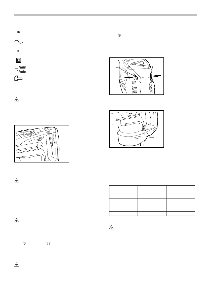
Switch action
1. Switch trigger
1
007858
FOR MODEL HR5211C
CAUTION:
• Before plugging in the tool, always check to see
that the switch trigger actuates properly and
returns to the "OFF" position when released.
To start the tool, simply pull the switch trigger. Release
the switch trigger to stop.
FOR MODELS HR5210C/ HR5201C
Trigger switch
CAUTION:
• Before plugging in the tool, always check to see
that the switch trigger actuates properly and
returns to the "OFF" position when released.
• This switch functions when setting the tool in
symbol and symbol modes.
To start the tool, simply pull the switch trigger. Release
the switch trigger to stop.
Slide switch
CAUTION:
• Before plugging in the tool, always check to see
that the tool is switched off.
• This switch functions only when setting the tool in
symbol action mode.
When using the tool in the hammering mode for a long
time, the slide switch is available. To start the tool, push
the "I (ON)" side of the switch lever. To stop the tool,
push the "O (OFF)" side of the switch lever.
1. Switch lever
1
007837
1
Speed change
1. Adjusting dial
1
007838
The revolutions and blows per minute can be adjusted
just by turning the adjusting dial. The dial is marked 1
(lowest speed) to 5 (full speed).
Refer to the table below for the relationship between the
number settings on the adjusting dial and the
revolutions/blows per minute.
Number on
adjusting dial
007903
5
4
3
2
1
Revolutions per
minute
260
240
190
150
130
Blows per minute
2,150
2,000
1,600
1,250
1,075
CAUTION:
• If the tool is operated continuously at low speeds
for a long time, the motor will get overloaded,
resulting in tool malfunction.
• The speed adjusting dial can be turned only as far
as 5 and back to 1. Do not force it past 5 or 1, or
the speed adjusting function may no longer work.
4
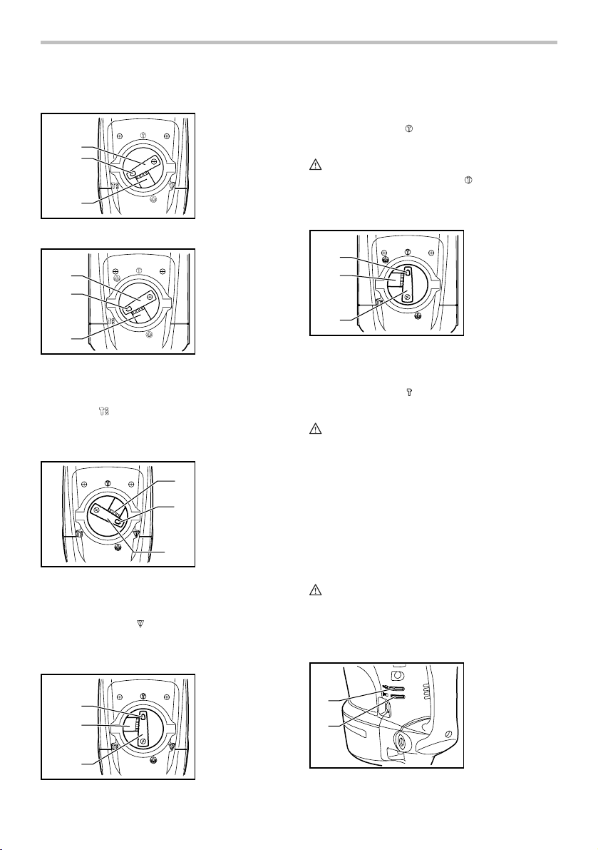
Selecting the action mode
Rotation with hammering
HR5201C
HR5210C
1
2
3
007839
HR5211C
1
2
For chipping, scaling or demolition operations, depress
1. Change lever
2. Pointer
3. Lock button
the lock button and rotate the change lever so that the
pointer points to the
chisel, scaling chisel, etc.
CAUTION:
• When using the tool in the symbol mode, the
switch trigger does not work and only the slide
1. Change lever
2. Pointer
3. Lock button
switch works.
FOR MODEL HR5211C
1
2
symbol. Use a bull point, cold
1. Pointer
2. Lock button
3. Change lever
3
007860
For drilling in concrete, masonry, etc., depress the lock
button and rotate the change lever so that the pointer
points to the
symbol. Use a tungsten-carbide tipped
bit.
Hammering only
FOR MODEL HR5201C AND HR5210C
1. Change lever
2. Pointer
3
3. Lock button
2
1
007902
For chipping, scaling or demolition operations, depress
the lock button and rotate the change lever so that the
pointer points to the
symbol. Use a bull point, cold
chisel, scaling chisel, etc.
For long time hammering (FOR MODELS HR5201C
AND HR5210C ONLY)
1. Pointer
2. Lock button
1
3. Change lever
2
3
007862
For chipping, scaling or demolition operations, depress
the lock button and rotate the change lever so that the
pointer points to the
chisel, scaling chisel, etc.
symbol. Use a bull point, cold
CAUTION:
• Do not rotate the change lever when the tool is
running under load. The tool will be damaged.
• To avoid rapid wear on the mode change
mechanism, be sure that the change lever is
always positively located in one of the two or three
action mode positions.
Torque limiter
The torque limiter will actuate when a certain torque
level is reached. The motor will disengage from the
output shaft. When this happens, the bit will stop turning.
CAUTION:
• As soon as the torque limiter actuates, switch off
the tool immediately. This will help prevent
premature wear of the tool.
Indicator lamp
1. Power-ON
indicator lamp
1
2
(green)
2. Service indicator
lamp (red)
007840
3
007863
5
The green power-ON indicator lamp lights up when the
tool is plugged. If the indicator lamp does not light up,
the mains cord or the controller may be defective. The
indicator lamp is lit but the tool does not start even if the
tool is switched on, the carbon brushes may be worn out,
or the controller, the motor or the ON/OFF switch may be
defective.
The red service indicator lamp flickers when the carbon
brushes are nearly worn out to indicate that the tool
needs servicing. After approx. 8 hours of use, the motor
will automatically be shut off.
ASSEMBLY
CAUTION:
• Always be sure that the tool is switched off and
unplugged before carrying out any work on the
tool.
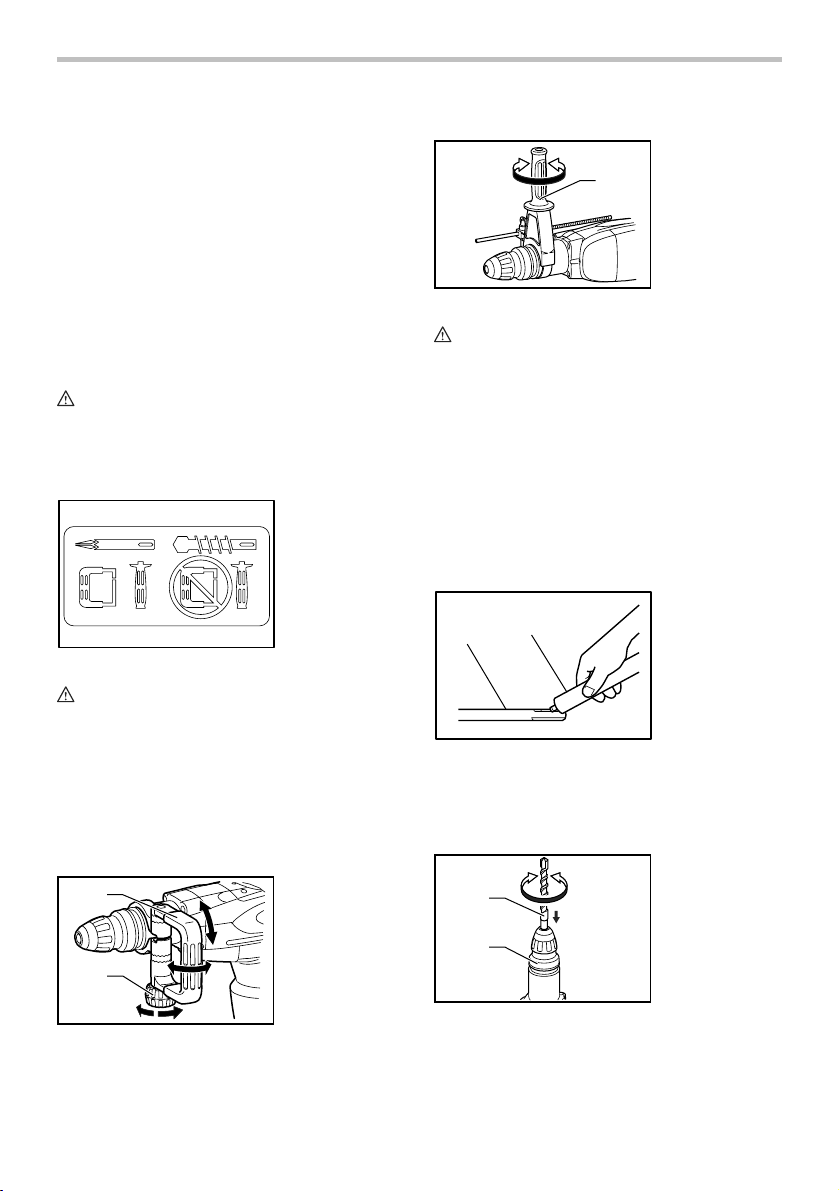
Side handle
003139
CAUTION:
• Use the side handle only when chipping, scaling or
demolishing. Do not use it when drilling in concrete,
masonry, etc. The tool cannot be held properly with
this side handle when drilling.
The side handle can be swung 360° on the vertical and
secured at any desired position. It also secures at eight
different positions back and forth on the horizontal. Just
loosen the clamp nut to swing the side handle to a
desired position. Then tighten the clamp nut securely.
1
1. Side handle
2. Clamp nut
Side grip
1. Side grip
1
007843
CAUTION:
• Always use the side grip to ensure operating safety
when drilling in concrete, masonry, etc.
The side grip swings around to either side, allowing easy
handling of the tool in any position. Loosen the side grip
by turning it counterclockwise, swing it to the desired
position and then tighten it by turning clockwise.
Bit grease (optional accessory)
Coat the bit shank head beforehand with a small amount
of bit grease (about 0.5 -1 g; 0.02 - 0.04 oz.). This chuck
lubrication assures smooth action and longer service
life.
Installing or removing the bit
1. Bit shank
1
003150
Clean the bit shank and apply bit grease before installing
the bit.
Insert the bit into the tool. Turn the bit and push it in until
it engages.
2
1
2. Bit grease
1. Bit
2. Chuck cover
007842
2
2
007844
If the bit cannot be pushed in, remove the bit. Pull the
chuck cover down a couple of times. Then insert the bit
again. Turn the bit and push it in until it engages.
6
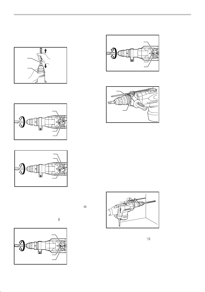
After installing, always make sure that the bit is securely
held in place by trying to pull it out.
To remove the bit, pull the chuck cover down all the way
and pull the bit out.
1. Bit
1
2
007845
2. Chuck cover
Bit angle (when chipping, scaling or
demolishing)
HR5201C
HR5210C
007846
HR5211C
007847
The bit can be secured at 16 different angles. To change
the bit angle, depress the lock button and rotate the
change lever so that the pointer points to the
Turn the bit to the desired angle.
Depress the lock button and rotate the change lever so
that the pointer points to the
that the bit is securely held in place by turning it slightly.
HR5201C
HR5210C
007864
1
2
3
2
3
1
1
2
3
1. Lock button
2. Change lever
3. Pointer
1. Change lever
2. Pointer
3. Lock button
symbol.
symbol. Then make sure
1. Change lever
2. Pointer
3. Lock button
HR5211C
007904
1
2
3
1. Change lever
2. Pointer
3. Lock button
Depth gauge
1
2
007848
The depth gauge is convenient for drilling holes of
uniform depth. Insert the depth gauge into the hole in the
grip base. Adjust the depth gauge to the desired depth
and then tighten the clamp screw to secure the depth
gauge.
NOTE:
• The depth gauge cannot be used at the position
where the depth gauge strikes against the tool
body.
1. Depth gauge
2. Clamp screw
OPERATION
Hammer drilling operation
007849
Set the change lever to the
Position the bit at the desired location for the hole, then
pull the switch trigger. Do not force the tool. Light
pressure gives best results. Keep the tool in position and
prevent it from slipping away from the hole.
Do not apply more pressure when the hole becomes
clogged with chips or particles. Instead, run the tool at
symbol.
7
an idle, then remove the bit partially from the hole. By
repeating this several times, the hole will be cleaned out
and normal drilling may be resumed.
CAUTION:
• There is a tremendous and sudden twisting force
exerted on the tool/bit at the time of hole
break-through, when the hole becomes clogged
with chips and particles, or when striking
reinforcing rods embedded in the concrete. Always
use the side grip (auxiliary handle) and firmly hold
the tool by both side grip and switch handle during
operations. Failure to do so may result in the loss
of control of the tool and potentially severe injury.
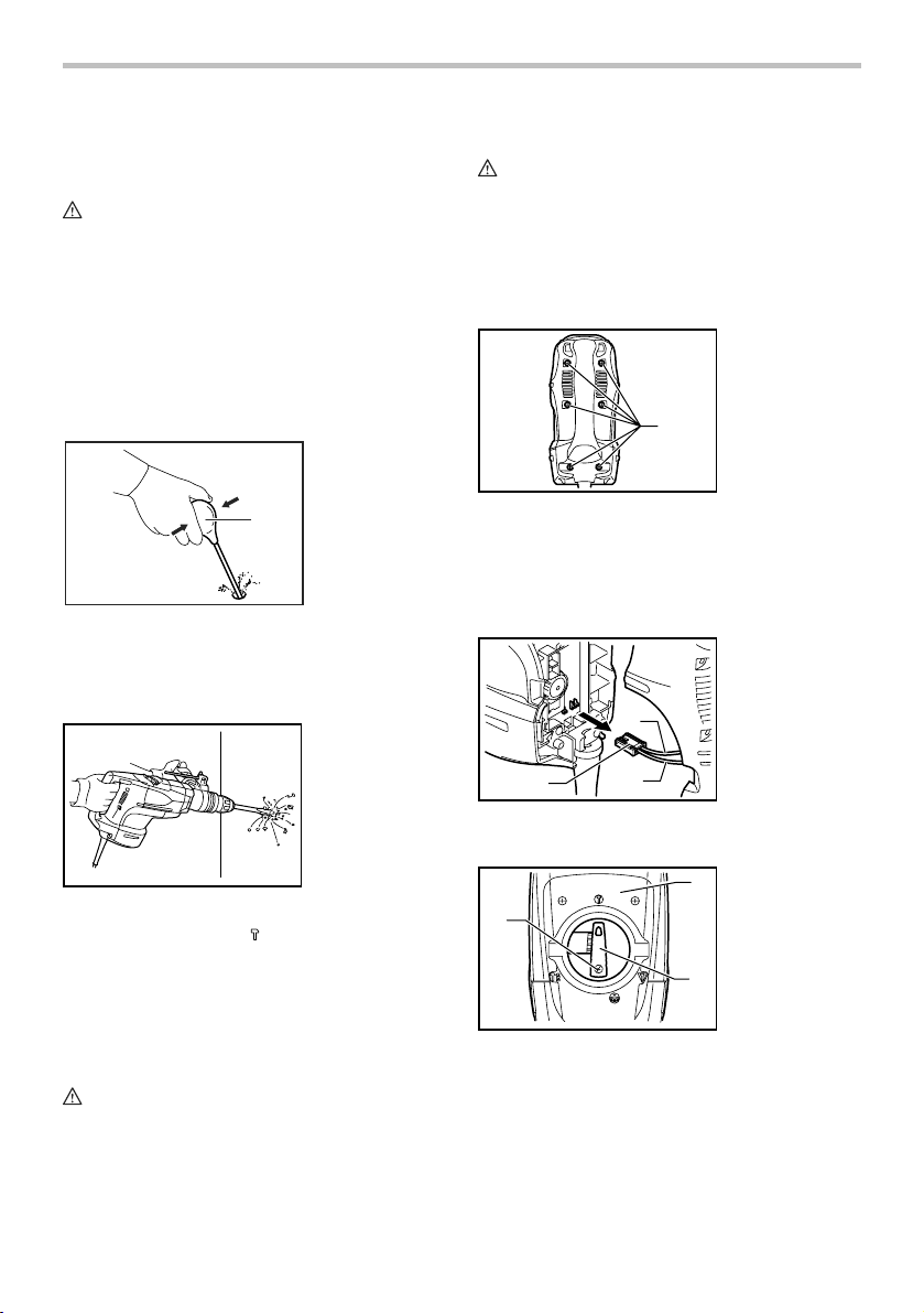
Blow-out bulb (optional accessory)
1. Blow-out bulb
1
002449
After drilling the hole, use the blow-out bulb to clean the
dust out of the hole.
Chipping/Scaling/Demolition
Lubrication
CAUTION:
• This servicing should be performed by Makita
Authorized or Factory Service Centers only.
This tool requires no hourly or daily lubrication because
it has a grease-packed lubrication system. It should be
relubricated after every 6 months of operation. Send the
complete tool to Makita Authorized or Factory Service
Center for this lubrication service.
1. Screws
1
007851
Run the tool for several minutes to warm it up. Switch off
and unplug the tool.
Loosen the six screws and remove the handle. Note that
the top screws are different from other screws.
Disconnect the connector by pulling them.
1. Black
2. White
3. Connector
1
007850
Set the change lever to the
symbol.
Hold the tool firmly with both hands. Turn the tool on and
apply slight pressure on the tool so that the tool will not
bounce around, uncontrolled. Pressing very hard on the
tool will not increase the efficiency.
MAINTENANCE
CAUTION:
• Always be sure that the tool is switched off and
unplugged before attempting to perform inspection
or maintenance.
3
007852
2
Loosen the screws and remove the change lever.
1. Change lever
3
2. Screw
2
3. Crank cap cover
1
007901
Remove the crank cap cover.
Remove the control plate. (Except for model HR5211C.)
8
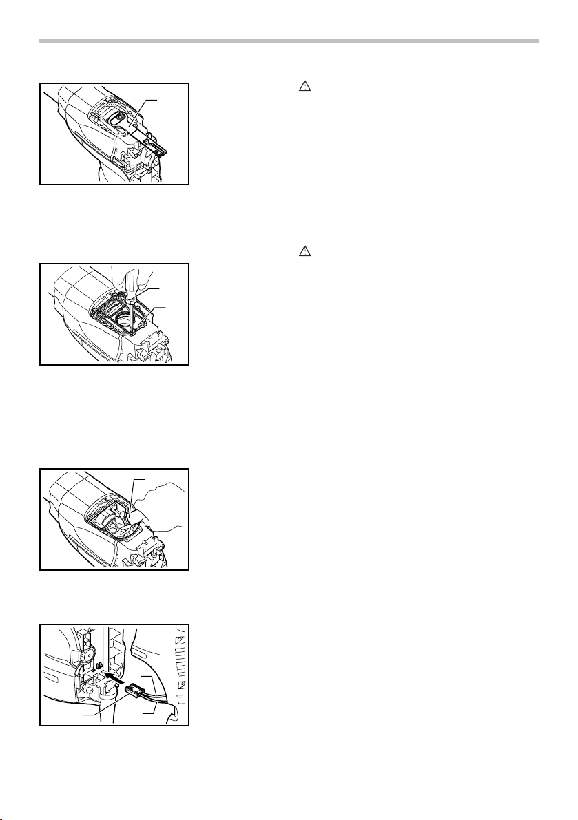
1. Control plate
1
007853
Loosen the six screws with a screwdriver and remove
the crank cap. Rest the tool on the table with the bit end
pointing upwards. This will allow the old grease to collect
inside the crank housing.
1. Screwdriver
2. Crank cap
1
2
007854
Wipe out the old grease inside and replace with a fresh
grease (60 g; 2 oz). Use only Makita genuine hammer
grease (optional accessory). Filling with more than the
specified amount of grease (approx. 60 g; 2 oz) can
cause faulty hammering action or tool failure. Fill only
with the specified amount of grease.
1
007855
1. Hammer grease
Reinstall the crank cap and tighten with the screwdriver.
Connect the connector and reinstall the handle.
1. Connector
2. Black
3. White
2
CAUTION:
• Do not tighten the crank cap excessively. It is made
of resin and is subject to breakage.
• Be careful not to damage the connector or lead
wires especially when wiping out the old grease or
installing the handle.
To maintain product SAFETY and RELIABILITY, repairs,
any other maintenance or adjustment should be
performed by Makita Authorized or Factory Service
Centers, always using Makita replacement parts.
ACCESSORIES
CAUTION:
• These accessories or attachments are
recommended for use with your Makita tool
specified in this manual. The use of any other
accessories or attachments might present a risk of
injury to persons. Only use accessory or
attachment for its stated purpose.
If you need any assistance for more details regarding
these accessories, ask your local Makita Service Center.
• Bull point
• Cold chisel
• Hammer grease
• Bit grease
• Depth gauge
• Blow-out bulb
• Safety goggles
• Plastic carrying case
• Scaling chisel
• Scraping chisel
• Clay spade
• Side handle
• Side grip
• SDS-Max Carbide-tipped bits
• Bushing tool
• Rammer
• Core bit adapter
• Core bit
007856
1
3
9

MAKITA LIMITED ONE YEAR WARRANTY
Warranty Policy
Every Makita tool is thoroughly inspected and tested
before leaving the factory. It is warranted to be free of
defects from workmanship and materials for the period
of ONE YEAR from the date of original purchase.
Should any trouble develop during this one year period,
return the COMPLETE tool, freight prepaid, to one of
Makita’s Factory or Authorized Service Centers. If
inspection shows the trouble is caused by defective
workmanship or material, Makita will repair (or at our
option, replace) without charge.
This Warranty does not apply where:
repairs have been made or attempted by others:
repairs are required because of normal wear and
tear:
the tool has been abused, misused or improperly
maintained:
alterations have been made to the tool.
IN NO EVENT SHALL MAKITA BE LIABLE FOR ANY
INDIRECT, INCIDENTAL OR CONSEQUENTIAL
DAMAGES FROM THE SALE OR USE OF THE
PRODUCT. THIS DISCLAIMER APPLIES BOTH
DURING AND AFTER THE TERM OF THIS
WARRANTY.
MAKITA DISCLAIMS LIABILITY FOR ANY IMPLIED
WARRANTIES, INCLUDING IMPLIED WARRANTIES
OF "MERCHANTABILITY" AND "FITNESS FOR A
SPECIFIC PURPOSE," AFTER THE ONE YEAR TERM
OF THIS WARRANTY.
This Warranty gives you specific legal rights, and you
may also have other rights which vary from state to
state. Some states do not allow the exclusion or
limitation of incidental or consequential damages, so
the above limitation or exclusion may not apply to you.
Some states do not allow limitation on how long an
implied warranty lasts, so the above limitation may not
apply to you.
EN0006-1
10