

Page 1
GB Rotary Hammer
Instruction Manual
F Perforateur
D Bohrhammer
I Martello rotativo
NL Boorhamer
E Martillo rotativo
P
Martelo misto Manual de instruções
DK
Borehammer Brugsanvisning
S
Borrhammare Bruksanvisning
N
Borhammer Bruksanvisning
SF
Pyörövasara Käyttöohje
GR Περιστροφικ σφυρί Οδηγίες χρήσεως
Manuel d’instructions
Betriebsanleitung
Istruzioni per l’uso
Gebruiksaanwijzing
Manual de instrucciones
HR4001C
HR4010C
HR4011C
Page 2

OFF
2
ON
1
12
HR4001C
HR4010C
3
5
4
6
34
HR4011C
5
4
6
HR4001C
HR4010C
6
5
4
56
HR4001C
HR4010C
5
6
HR4011C
6
4
5
4
78
2
Page 3
9
7
8
910
9
10
11 12
12
13
13 14
14
14
15
HR4001C
HR4010C
11
5
6
15
15 16
4
3
Page 4
HR4011C
5
6
4
17 18
HR4001C
HR4010C
5
6
4
HR4011C
5
6
4
19 20
21 22
16
17
18
23 24
4
19
Page 5
20
21
22
25 26
25
27 28
24
23
4
26
27
28
29 30
20
21
22
5
Page 6

Symbols
The followings show the symbols used for the tool. Be sure that you understand their meaning before use.
Symboles
Nous donnons ci-dessous les symboles utilisés pour l’outil. Assurez-vous que vous en avez bien compris la signification avant d’utiliser l’outil.
Symbole
Die folgenden Symbole werden für die Maschine verwendet. Machen Sie sich vor der Benutzung unbedingt mit ihrer
Bedeutung vertraut.
Simboli
Per questo utensile vengono usati i simboli seguenti. Bisogna capire il loro significato prima di usare l’utensile.
Symbolen
Voor dit gereedschap worden de volgende symbolen gebruikt. Zorg ervoor dat u de betekenis van deze symbolen
begrijpt alvorens het gereedschap te gebruiken.
Símbolos
A continuación se muestran los símbolos utilizados con esta herramienta. Asegúrese de que entiende su significado
antes de usarla.
Símbolos
O seguinte mostra os símbolos utilizados para a ferramenta. Certifique-se de que compreende o seu significado antes
da utilização.
Symboler
Nedenstående symboler er anvendt i forbindelse med denne maskine. Vær sikker på, at De har forstået symbolernes
betydning, før maskinen anvendes.
Symboler
Det följande visar de symboler som används för den här maskinen. Se noga till att du förstår deras innebörd innan
maskinen används.
Symbolene
Følgende viser de symblene som brukes for maskinen. Det er viktig å forstå betydningen av disse før maskinen tas i
bruk.
Symbolit
Alla on esitetty koneessa käytetyt symbolit. Opettele näiden merkitys, ennen kuin käytät konetta.
Σύµβολα
Τα ακλουθα δείχνουν τα σύµβολα που χρησιµοποιούνται για το µηχάνηµα. Βεβαιωθείτε τι καταλαβαίνετε
τη σηµασία τους πριν απ τη χρήση.
❏ Read instruction manual.
❏ Lire le mode d’emploi.
❏ Bitte Betriebsanleitung lesen.
❏ Leggete il manuale di istruzioni.
❏ Lees de gebruiksaanwijzing.
❏ Lea el manual de instrucciones.
❏ Leia o manual de instruções.
❏ Læs brugsanvisningen.
❏ Läs bruksanvisningen.
❏ Les bruksanvisingen.
❏ Katso käyttöohjeita.
❏ ∆ιαβάστε τις οδηγίες χρήσης.
❏ DOUBLE INSULATION
❏ DOUBLE ISOLATION
❏ DOPPELT SCHUTZISOLIERT
❏ DOPPIO ISOLAMENTO
❏ DUBBELE ISOLATIE
❏ DOBLE AISLAMIENTO
❏ DUPLO ISOLAMENTO
❏ DOBBELT ISOLATION
❏ DUBBEL ISOLERING
❏ DOBBEL ISOLERING
❏ KAKSINKERTAINEN ERISTYS
❏ ∆ΙΠΛΗ ΜΟΝΩΣΗ
6
Page 7
ENGLISH
Explanation of general view
1 Switch trigger
2 Switch lever
3 Adjusting dial
4 Change lever
5 Pointer
6 Lock button
7 Power-ON indicator lamp
(green)
8 Service indicator lamp (red)
9 Side handle
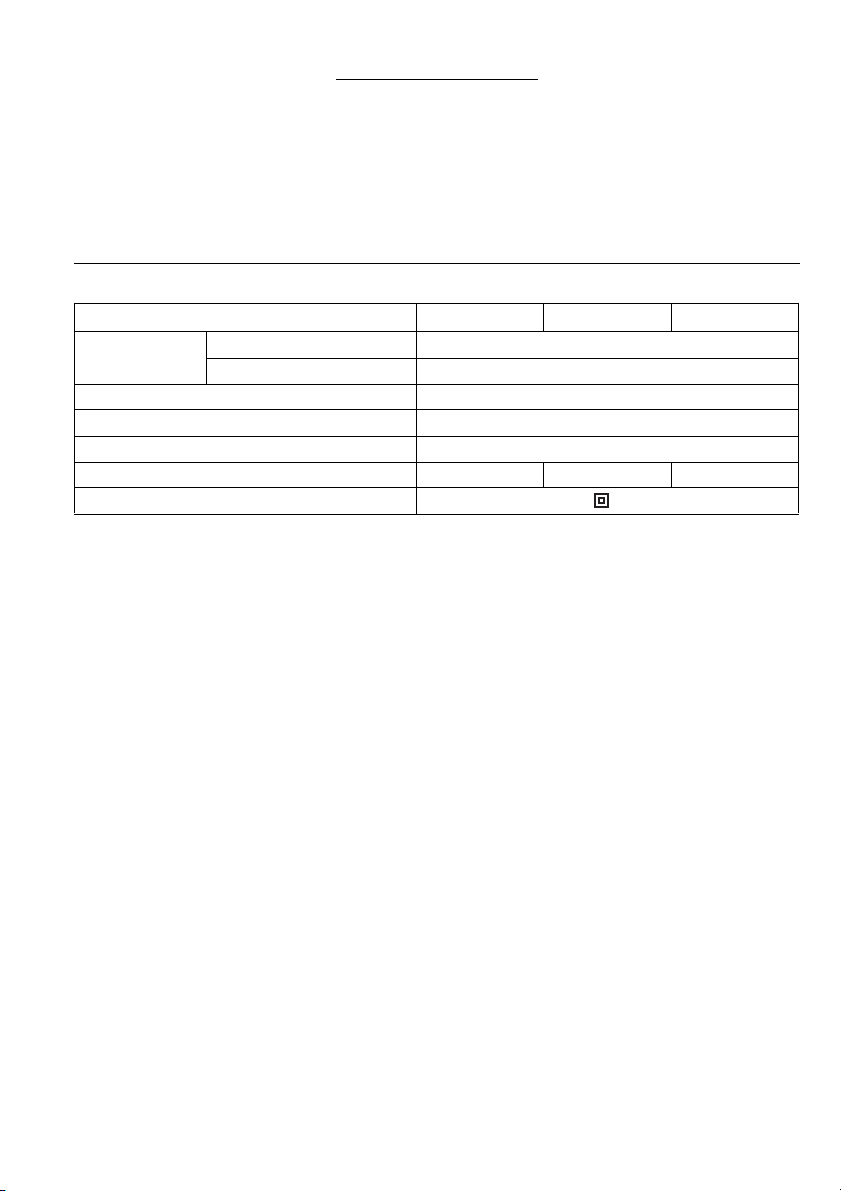
SPECIFICATIONS
Model HR4001C HR4010C HR4011C
Capacities
No load speed (min
Blows per minute 1,350 – 2,750
• Due to our continuing program of research and devel-
opment, the specifications herein are subject to change
without notice.
• Note: Specifications may differ from country to country.
Intendended use
The tool is intended for hammer drilling in brick, concrete
and stone as well as for chiselling work.
Power supply
The tool should be connected only to a power supply of
the same voltage as indicated on the nameplate, and can
only be operated on single-phase AC supply. They are
double-insulated in accordance with European Standard
and can, therefore, also be used from sockets without
earth wire.
Safety hints
For your own safety, please refer to the enclosed safety
instructions.
Carbide-tipped bit 40 mm
Overall length 468 mm
Net weight 5.9 kg 6.3 kg 6.3 kg
Safety class /II
ADDITIONAL SAFETY RULES
1. Wear ear protectors. Exposure to noise can cause
hearing loss.
2. Use auxiliary handles supplied with the tool.
Loss of control can cause personal injury.
3. Hold tools by insulated gripping surfaces when
performing an operation where the cutting tool
may contact hidden wiring or its own cord. Con-
tact with a “live” wire will make exposed metal parts
of the tool “live” and shock the operator.
4. Wear a hard hat (safety helmet), safety glasses
and/or face shield. It is also highly recom-
mended that you wear a dust mask and thickly
padded gloves.
5. Be sure the bit is secured in place before opera-
tion.
10 Clamp nut
11 Side grip
12 Bit shank
13 Bit grease
14 Bit
15 Chuck cover
16 Depth gauge
17 Clamp screw
18 Blow-out bulb
19 Screws
Core bit 105 mm
–1
) 235 – 480
ENB010-2
20 Connector
21 Black
22 White
23 Screw
24 Crank cap cover
25 Control plate
26 Screwdriver
27 Crank cap
28 Hammer grease
6. Under normal operation, the tool is designed to
produce vibration. The screws can come loose
easily, causing a breakdown or accident. Check
tightness of screws carefully before operation.
7. In cold weather or when the tool has not been
used for a long time, let the tool warm up for a
while by operating it under no load. This will
loosen up the lubrication. Without proper warmup, hammering operation is difficult.
8. Always be sure you have a firm footing.
Be sure no one is below when using the tool in
high locations.
9. Hold the tool firmly with both hands.
10. Keep hands away from moving parts.
11. Do not leave the tool running. Operate the tool
only when hand-held.
12. Do not point the tool at any one in the area when
operating. The bit could fly out and injure someone seriously.
13. Do not touch the bit or parts close to the bit
immediately after operation; they may be
extremely hot and could burn your skin.
SAVE THESE INSTRUCTIONS.
7
Page 8

FUNCTIONAL DESCRIPTION
CAUTION:
• Always be sure that the tool is switched off and
unplugged before adjusting or checking function on the
tool.
Switch action
FOR MODEL HR4011C
CAUTION:
• Before plugging in the tool, always check to see that
the switch trigger actuates properly and returns to the
“OFF” position when released.
To start the tool, simply pull the switch trigger. Release
the switch trigger to stop. (Fig. 1)
FOR MODELS HR4010C AND HR4001C
Trigger switch
CAUTION:
• Before plugging in the tool, always check to see that
the switch trigger actuates properly and returns to the
“OFF” position when released.
• This switch functions when setting the tool in symbol and symbol modes.
To start the tool, simply pull the switch trigger. Release
the switch trigger to stop. (Fig. 1)
Slide switch
CAUTION:
• Before plugging in the tool, always check to see that
the tool is switched off.
• This switch functions only when setting the tool in
symbol action mode.
When using the tool in the hammering mode for a long
time, the slide switch is available. To start the tool, push
the “I (ON)” side of the switch lever. To stop the tool, push
the “O (OFF)” side of the switch lever. (Fig. 2)
Speed change (Fig. 3)
The revolutions and blows per minute can be adjusted
just by turning the adjusting dial. The dial is marked 1
(lowest speed) to 5 (full speed).
Refer to the table below for the relationship between the
number settings on the adjusting dial and the revolutions/
blows per minute.
Number on
adjusting dial
5 480 2,750
4 440 2,550
3 360 2,050
2 270 1,550
1 230 1,350
CAUTION:
• If the tool is operated continuously at low speeds for a
long time, the motor will get overloaded, resulting in
tool malfunction.
• The speed adjusting dial can be turned only as far as 5
and back to 1. Do not force it past 5 or 1, or the speed
adjusting function may no longer work.
Revolutions
per minute
Blows
per minute
Selecting the action mode
Rotation with hammering (Fig. 4 & 5)
For drilling in concrete, masonry, etc., depress the lock
button and rotate the change lever so that the pointer
points to the symbol. Use a tungsten-carbide tipped
bit.
Hammering only
FOR MODELS HR4001C AND HR4010C (Fig. 6)
For chipping, scaling or demolition operations, depress
the lock button and rotate the change lever so that the
pointer points to the symbol. Use a bull point, cold
chisel, scaling chisel, etc.
For long time hammering (FOR MODELS HR4001C
AND HR4010C ONLY) (Fig. 7)
For chipping, scaling or demolition operations, depress
the lock button and rotate the change lever so that the
pointer points to the symbol. Use a bull point, cold
chisel, scaling chisel, etc.
CAUTION:
• When using the tool in the symbol mode, the switch
trigger does not work and only the slide switch works.
FOR MODEL HR4011C (Fig. 8)
For chipping, scaling or demolition operations, depress
the lock button and rotate the change lever so that the
pointer points to the symbol. Use a bull point, cold
chisel, scaling chisel, etc.
CAUTION:
• Do not rotate the change lever when the tool is running
under load. The tool will be damaged.
• To avoid rapid wear on the mode change mechanism,
be sure that the change lever is always positively
located in one of the two or three action mode positions.
Torque limiter
The torque limiter will actuate when a certain torque level
is reached. The motor will disengage from the output
shaft. When this happens, the bit will stop turning.
CAUTION:
• As soon as the torque limiter actuates, switch off the
tool immediately. This will help prevent premature wear
of the tool.
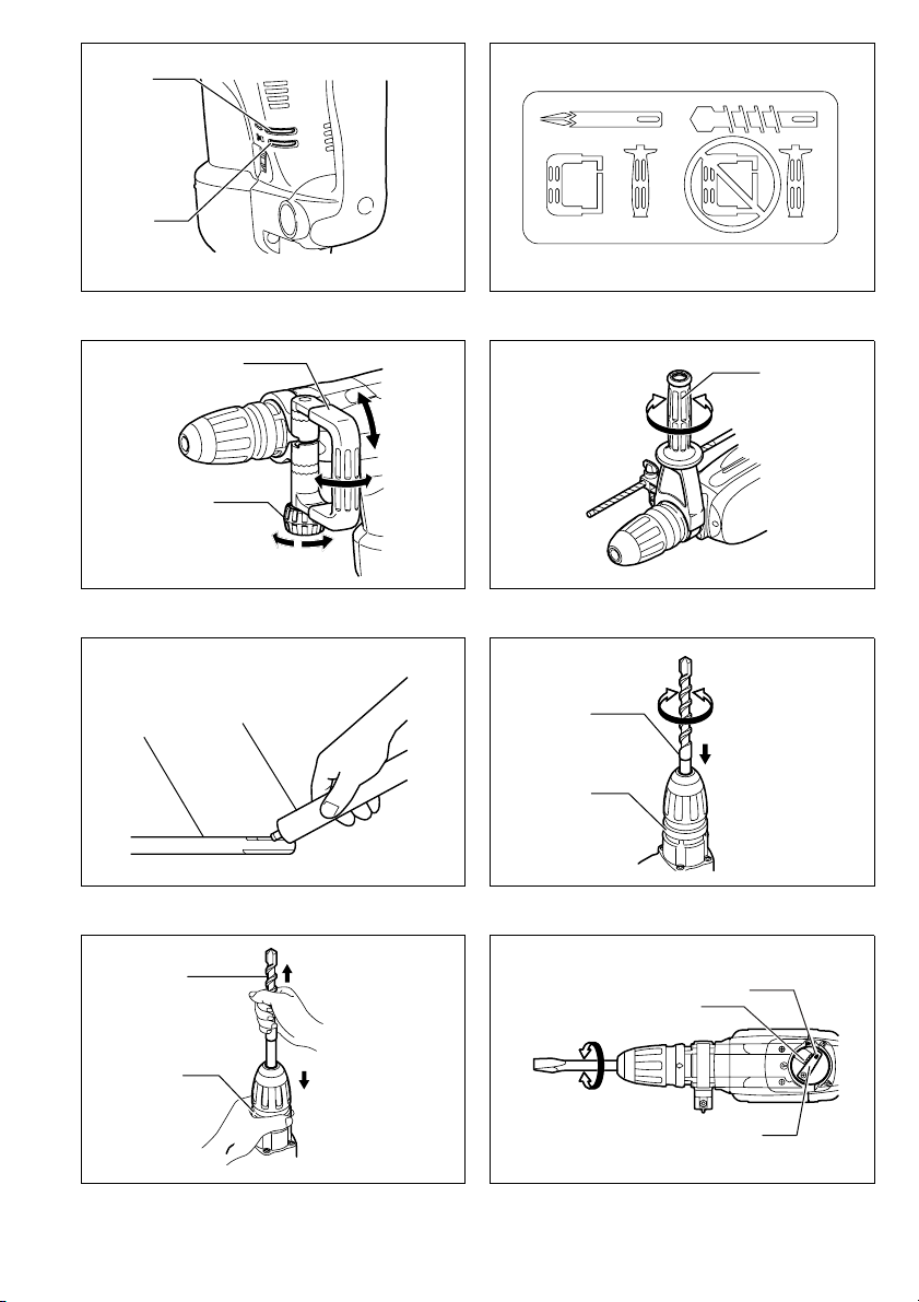
Indicator lamp (Fig. 9)
The green power-ON indicator lamp lights up when the
tool is plugged. If the indicator lamp does not light up, the
mains cord or the controller may be defective. The indicator lamp is lit but the tool does not start even if the tool is
switched on, the carbon brushes may be worn out, or the
controller, the motor or the ON/OFF switch may be defective.
The red service indicator lamp lights up when the carbon
brushes are nearly worn out to indicate that the tool
needs servicing. After approx. 8 hours of use, the motor
will automatically be shut off.
8
Page 9

ASSEMBLY
CAUTION:
• Always be sure that the tool is switched off and
unplugged before carrying out any work on the tool.
Side handle
CAUTION:
• Use the side handle only when chipping, scaling or
demolishing. Do not use it when drilling in concrete,
masonry, etc. The tool cannot be held properly with this
side handle when drilling. (Fig. 10)
The side handle can be swung 360° on the vertical and
secured at any desired position. It also secures at eight
different positions back and forth on the horizontal. Just
loosen the clamp nut to swing the side handle to a
desired position. Then tighten the clamp nut securely.
(Fig. 11)
Side grip (Fig. 12)
CAUTION:
• Always use the side grip to ensure operating safety
when drilling in concrete, masonry, etc.
The side grip swings around to either side, allowing easy
handling of the tool in any position. Loosen the side grip
by turning it counterclockwise, swing it to the desired
position and then tighten it by turning clockwise.
Installing or removing the bit
Clean the bit shank and apply bit grease before installing
the bit. (Fig. 13)
Insert the bit into the tool. Turn the bit and push it in until
it engages.
If the bit cannot be pushed in, remove the bit. Pull the
chuck cover down a couple of times. Then insert the bit
again. Turn the bit and push it in until it engages.
After installing, always make sure that the bit is securely
held in place by trying to pull it out. (Fig. 14)
To remove the bit, pull the chuck cover down all the way
and pull the bit out. (Fig. 15)
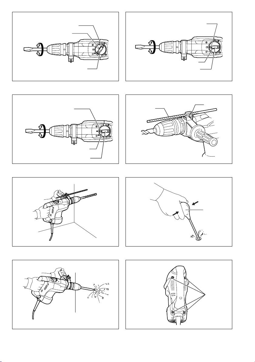
Bit angle (when chipping, scaling or demolishing)
The bit can be secured at 12 different angles. To change
the bit angle, depress the lock button and rotate the
change lever so that the pointer points to the symbol.
Turn the bit to the desired angle. (Fig. 16 & 17)
Depress the lock button and rotate the change lever so
that the pointer points to the symbol. Then make sure
that the bit is securely held in place by turning it slightly.
(Fig. 18 & 19)
Depth gauge (Fig. 20)
The depth gauge is convenient for drilling holes of uniform depth. Loosen the clamp screw and adjust the
depth gauge to the desired depth. After adjusting, tighten
the clamp screw firmly.
NOTE:
• The depth gauge cannot be used at the position where
the depth gauge strikes against the gear housing/motor
housing.
OPERATION
Hammer drilling operation (Fig. 21)
Set the change lever to the symbol.
Position the bit at the desired location for the hole, then
pull the switch trigger. Do not force the tool. Light pressure gives best results. Keep the tool in position and prevent it from slipping away from the hole.
Do not apply more pressure when the hole becomes
clogged with chips or particles. Instead, run the tool at an
idle, then remove the bit partially from the hole. By
repeating this several times, the hole will be cleaned out
and normal drilling may be resumed.
CAUTION:
• When the bit begins to break through concrete or if the
bit strikes reinforcing rods embedded in concrete, the
tool may react dangerously. Maintain good balance and
safe footing while holding the tool firmly with both
hands to prevent dangerous reaction.
Blow-out bulb (optional accessory) (Fig. 22)
After drilling the hole, use the blow-out bulb to clean the
dust out of the hole.
Chipping/Scaling/Demolition (Fig. 23)
Set the change lever to the symbol.
Hold the tool firmly with both hands. Turn the tool on and
apply slight pressure on the tool so that the tool will not
bounce around, uncontrolled. Pressing very hard on the
tool will not increase the efficiency.
MAINTENANCE
CAUTION:
• Always be sure that the tool is switched off and
unplugged before attempting to perform inspection or
maintenance.
Lubrication
CAUTION:
• This servicing should be performed by Makita Authorized or Factory Service Centers only.
This tool requires no hourly or daily lubrication because it
has a grease-packed lubrication system. Lubricate the
tool every time the carbon brushes are replaced.
Run the tool for several minutes to warm it up. Switch off
and unplug the tool.
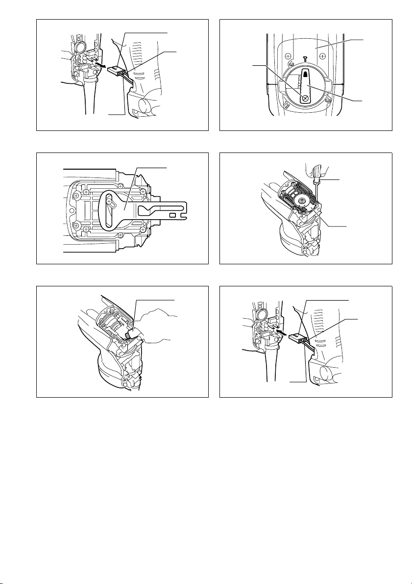
Loosen the four screws and remove the handle. Note that
the top screws are different from other screws. (Fig. 24)
Disconnect the connector by pulling them. (Fig. 25)
Loosen the screws and remove the change lever.
Remove the crank cap cover. (Fig. 26)
Remove the control plate. (Except for model HR4011C.)
(Fig. 27)
Loosen the six screws with a screwdriver and remove the
crank cap. Rest the tool on the table with the bit end
pointing upwards. This will allow the old grease to collect
inside the crank housing. (Fig. 28)
Wipe out the old grease inside and replace with a fresh
grease (60 g). Use only Makita genuine hammer grease
(optional accessory). Filling with more than the specified
amount of grease (approx. 60 g) can cause faulty hammering action or tool failure. Fill only with the specified
amount of grease.
Reinstall the crank cap and tighten with the screwdriver.
(Fig. 29)
Connect the connector and reinstall the handle. (Fig. 30)
9
Page 10

CAUTION:
• Do not tighten the crank cap excessively. It is made of
resin and is subject to breakage.
• Be careful not to damage the connector or lead wires
especially when wiping out the old grease or installing
the handle.
To maintain product SAFETY and RELIABILITY, repairs,
any other maintenance or adjustment should be performed by Makita Authorized Service Centers, always
using Makita replacement parts.
ACCESSORIES
CAUTION:
• These accessories or attachments are recommended
for use with your Makita tool specified in this manual.
The use of any other accessories or attachments might
present a risk of injury to persons. Only use accessory
or attachment for its stated purpose.
If you need any assistance for more details regarding
these accessories, ask your local Makita service center.
• SDS-MAX Carbide tipped bit
• SDS-MAX bull point
• SDS-MAX cold chisel
• SDS-MAX scaling chisel
• SDS-MAX tile chisel
• SDS-MAX clay spade
• Hammer grease
• Bit grease
• Side handle
• Side grip
• Depth gauge
• Blow-out bulb
• Safety goggle
• Carrying case
10
Page 11

NEDERLANDS
Verklaring van algemene gegevens
1 Aan/uit-schakelaar
2 Blokkeerschakelaar
3 Stelwiel
4 Functiekeuzeschakelaar
5 Wijzer
6 Vergrendelknop
7 Voedingsindicatielampje (groen)
8 Onderhoudsindicatielampje
(rood)
9 Verstelbare D-handgreep
TECHNISCHE GEGEVENS
Model HR4001C HR4010C HR4011C
Capaciteiten
• In verband met ononderbroken research en ontwikkeling behouden wij ons het recht voor bovenstaande
technische gegevens te wijzigen zonder voorafgaande
kennisgeving.
• Opmerking: De technische gegevens kunnen van land
tot land verschillen.
Doeleinden van gebruik
De machine is bestemd voor het hamerboren in baksteen, beton en steen en ook voor beitelwerk.
Stroomvoorziening
De machine mag alleen worden aangesloten op een
stroombron van hetzelfde voltage als aangegeven op de
naamplaat, en kan alleen op enkel-fase wisselstroom
worden gebruikt. De machine is dubbel-geïsoleerd volgens de Europese standaard en kan derhalve ook op
een niet-geaard stopkontakt worden aangesloten.
Veiligheidswenken
Voor uw veiligheid dient u de bijgevoegde Veiligheidsvoorschriften nauwkeurig op te volgen.
Boor met hardmetalen snijvlak 40 mm
Toerental onbelast (min
Slagen per minuut 1 350 – 2 750
Totale lengte 468 mm
Netto gewicht 5,9 kg 6,3 kg 6,3 kg
Veiligheidsklasse /II
10 Klemschroef
11 Extra handgreep
12 Insteekeinde van het gereed-
schap
13 Een beetje vet
14 Gereedschap
15 Vergrendelingshuls
16 Diepteaanslag
17 Klemschroef
18 Blaasbalgje
Kernboor 105 mm
–1
) 235 – 480
19 Schroeven
20 Contrastekker
21 Zwart
22 Wit
23 Schroef
24 Afdekking krukasdeksel
25 Besturingsplaatje
26 Schroevendraaier
27 Krukasdeksel
28 Smeermiddel voor boorhamers
AANVULLENDE
VEILIGHEIDSVOORSCHRIFTEN
1. Draag oorbeschermers. Blootstelling aan geluid
kan gehoorsverlies tot gevolg hebben.
2. Gebruik de extra handgrepen die met de
machine bijgeleverd zijn. Verlies van controle over
de machine kan persoonlijk letsel veroorzaken.
3. Houd het gereedschap tijdens het werk vast bij
de geïsoleerde handgrepen wanneer er kans is
dat de boor op verborgen elektrische draden of
op zijn eigen netsnoer zal stoten. Door contact
met onder spanning staande draden zullen de metalen delen van het gereedschap onder spanning
komen te staan zodat de gebruiker een elektrische
schok kan krijgen.
4. Draag een veiligheidshelm, veiligheidsbril en/of
gezichtsbescherming. Het wordt sterk aanbevolen om een stofmasker en dikke werkhandschoenen te dragen.
5. Controleer of de boor goed vastgezet is alvorens
met uw werk te beginnen.
6. Tijdens normale bediening brengt dit gereedschap trillingen voort. De schroeven kunnen
daarom gemakkelijk loskomen, met een defect of
ongeluk als mogelijk gevolg.
7. Controleer vóór het gebruik of alle schroeven
goed vastzitten. Laat het gereedschap een tijdje
onbelast warmdraaien wanneer het koud weer is
of wanneer het gereedschap voor langere tijd
niet werd gebruikt. Hierdoor zal het smeermiddel
vloeibaar worden. Hameren is moeilijk indien het
gereedschap niet goed warmgedraaid is.
23
Page 12

8. Zorg ervoor dat u altijd stevige steun voor de
voeten hebt.
Controleer of er zich niemand beneden u bevindt
wanneer u het gereedschap op een hoge plaats
gaat gebruiken.
9. Houd het gereedschap stevig vast met beide
handen.
10. Houd uw handen uit de buurt van draaiende
onderdelen.
11. Laat het gereedschap niet achter terwijl het nog
in bedrijf is. Bedien het gereedschap alleen wanneer u het met beide handen vasthoudt.
12. Richt het gereedschap tijdens het gebruik niet
op personen die zich in de nabije omgeving
bevinden. De boor zou kunnen losraken en ernstige verwondingen veroorzaken.
13. Raak de boor of onderdelen in de nabije omgeving van de boor niet aan onmiddellijk na het
gebruik. Deze kunnen erg heet zijn en brandwonden veroorzaken.
BEWAAR DEZE VOORSCHRIFTEN.
BESCHRIJVING VAN DE FUNCTIES
LET OP:
• Controleer altijd of het gereedschap is uitgeschakeld
en zijn stekker uit het stopcontact is verwijderd alvorens de functies op het gereedschap te controleren of
af te stellen.
In- en uitschakelen
VOOR HET MODEL HR4011C
LET OP:
• Voordat u de stekker in het stopcontact steekt moet u
de juiste werking van de aan/uit-schakelaar controleren
en dat bij het loslaten deze schakelaar in de stand
“OFF” terugkeert.
Druk de aan/uit-schakelaar in en houd deze ingedrukt
om de machine in te schakelen. Laat de aan/uit-schakelaar los om de machine uitschakelen. (Fig. 1)
VOOR DE MODELLEN HR4010C EN HR4001C
Aan/uit-schakelaar
LET OP:
• Voordat u de stekker in het stopcontact steekt moet u
de juiste werking van de aan/uit-schakelaar controleren
en dat bij het loslaten deze schakelaar in de stand
“OFF” terugkeert.
• Deze schakelaar werkt wanneer de machine in de
bedieningsfunctie en staat.
Druk de aan/uit-schakelaar in en houd deze ingedrukt
om de machine in te schakelen. Laat de aan/uit-schakelaar los om de machine uitschakelen. (Fig. 1)
Blokkeerschakelaar
LET OP:
• Controleer altijd dat de machine uitgeschakeld is voor-
dat u de stekker in het stopcontact steekt.
• Deze schakelaar werkt alleen wanneer de machine in
de bedieningsfunctie staat.
De blokkeerschakelaar is handig als u langdurig met de
machine moet hamerboren. Schakel de machine in door
op de “I (ON)”-kant van deze wipschakelaar te drukken.
Schakel de machine uit door op de “O (OFF)”-kant van
deze wipschakelaar te drukken. (Fig. 2)
Toerental of aantal slagen wijzigen (Fig. 3)
Door verdraaien van het stelwiel kan het aantal toeren of
slagen per minuut worden veranderd. De markering op
het stelwiel is van 1 (laagste toerental/aantal slagen) tot
5 (hoogste toerental/aantal slagen).
Raadpleeg onderstaande tabel voor het verband tussen
instelnummers op het stelwiel en het toerental/aantal slagen per minuut.
Nummers op
het stelwiel
5 480 2 750
4 440 2 550
3 360 2 050
2 270 1 550
1 230 1 350
LET OP:
• Door voortdurend en langdurig gebruik van de machine
met een laag toerental kan de motor overbelast worden
en een defect aan de machine veroorzaken.
• Het stelwiel kan alleen maar tot de stand 5 en terug tot
de stand 1 verdraaid worden. Forceer het stelwiel niet
voorbij de stand 5 of 1, omdat anders de toerentalregeling niet meer functioneert.
Toerental
Slagen per
minuut
De bedieningsfunctie kiezen
Hamerboren (Fig. 4 en 5)
Voor boren in beton, steen, e.d., druk de vergrendelknop
in en verdraai de functiekeuzeschakelaar totdat de wijzer
naar het -pictogram wijst. Gebruik een boor met een
hardmetalen snijvlak.
Alleen beitelen
VOOR DE MODELLEN HR4001C EN HR4010C (Fig. 6)
Voor hak-, bik- of sloopwerkzaamheden, druk de vergrendelknop in en verdraai de functiekeuzeschakelaar
totdat de wijzer naar het -pictogram wijst. Gebruik een
puntbeitel, platte of brede beitel, enz.
Langdurig beitelen (ALLEEN VOOR DE MODELLEN
HR4001C EN HR4010C) (Fig. 7)
Voor hak-, bik- of sloopwerkzaamheden, druk de vergrendelknop in en verdraai de functiekeuzeschakelaar
totdat de wijzer naar het -pictogram wijst. Gebruik
een puntbeitel, platte of brede beitel, enz.
LET OP:
• Als de machine ingesteld staat op de functie . werkt
de aan/uit-schakelaar niet, alleen de blokkeerschakelaar functioneert.
24
Page 13

VOOR HET MODEL HR4011C (Fig. 8)
Voor hak-, bik- of sloopwerkzaamheden, druk de vergrendelknop in en verdraai de functiekeuzeschakelaar
totdat de wijzer naar het -pictogram wijst. Gebruik een
puntbeitel, platte of brede beitel, enz.
LET OP:
• De functiekeuzeschakelaar mag alleen worden
bediend wanneer de machine stilstaat. Anders raakt de
machine beschadigd.
• Om versnelde slijtage van het functiekeuzemechaniek
te voorkomen moet u ervoor zorgen dat de keuzeschakelaar altijd duidelijk in een van de twee of drie bedieningsfunctiestanden staat.
Slipkoppeling
De slipkoppeling treedt in werking bij het bereiken van
een bepaald draaimoment. De verbinding tussen aandrijving en uitgaande as wordt onderbroken. Als dit gebeurd
zal de boor niet meer draaien.
LET OP:
• Zodra de slipkoppeling in werking treedt moet u de
machine uitschakelen. Hierdoor helpt u voortijdige slijtage van de machine te voorkomen.
Indicatielampje (Fig. 9)
Het groene voedingsindicatielampje (“ON”) gaat branden
als de stekker in het stopcontact is gestoken. Als het indicatielampje niet brandt kan het netsnoer of de regeleenheid defect zijn. Als het indicatielampje brandt en de
machine functioneert niet, ook als deze is ingeschakeld,
kunnen de koolborstels versleten zijn, of de regeleenheid, motor of aan/uit-schakelaar defect zijn.
Het rode onderhoudsindicatielampje gaat branden als de
koolborstels bijna versleten zijn en om aan te geven dat
de machine onderhoud nodig heeft. Na een gebruiksduur
van circa 8 uur wordt de machine automatisch uitgeschakeld.
INEENZETTEN
LET OP:
• Zorg altijd dat het gereedschap is uitgeschakeld en zijn
stekker uit het stopcontact is verwijderd alvorens enig
werk aan het gereedschap uit te voeren.
Verstelbare D-handgreep
LET OP:
• Gebruik de verstelbare D-handgreep alleen bij hak-,
bik- of sloopwerkzaamheden. Gebruik het niet bij boorwerkzaamheden in beton, steen, enz. Met deze Dhandgreep kan men tijdens het boren de machine niet
op de juiste wijze vasthouden. (Fig. 10)
De D-handgreep kan 360° in verticale richting zwenken
en in elke stand vastgezet worden. De handgreep kan
ook in acht verschillende standen naar voren en achter in
horizontale richting vastgezet worden. Maak alleen maar
de klemschroef los en draai de D-handgreep naar de
gewenste stand. Draai de klemschroef daarna weer stevig vast. (Fig. 11)
Extra handgreep (Fig. 12)
LET OP:
• Gebruik altijd de extra handgreep om boorwerkzaamheden in beton, steen, e.d. veilig uit te voeren.
Voor het gemakkelijk hanteren van de machine in elke
stand, kan de extra handgreep aan weerszijden zwenken. Draai de handgreep los door het greepstuk linksom
te draaien, zwenk de handgreep in de gewenste stand en
draai het weer vast door het greepstuk rechtsom te
draaien.
Gereedschap inklemmen of verwijderen
Reinig het insteekeinde van het gereedschap en smeer
het in met een beetje vet. (Fig. 13)
Steek het gereedschap draaiend in de machine tot het
automatisch wordt vergrendeld.
Verwijder het gereedschap als deze niet in de machine
gestoken kan worden. Trek de vergrendelingshuls een
paar keer naar achteren. Steek het gereedschap daarna
weer draaiend in de machine tot het automatisch wordt
vergrendeld.
Controleer na het inklemmen de vergrendeling door aan
het gereedschap te trekken. (Fig. 14)
Trek, om het gereedschap te verwijderen, de vergrendelingshuls helemaal naar achteren en haal het gereedschap uit de machine. (Fig. 15)
Beitelstand
(voor hak-, bik- of sloopwerkzaamheden)
De beitel kan in 12 standen worden vergrendeld. Druk,
om de beitelstand te wijzigen, de vergrendelknop in en
verdraai de functiekeuzeschakelaar totdat de wijzer naar
het -pictogram wijst. Draai de beitel in de gewenste
beitelstand. (Fig. 16 en 17)
Druk de vergrendelknop in en verdraai de functiekeuzeschakelaar totdat de wijzer naar het -pictogram wijst.
Controleer de vergrendeling van het gereedschap door
het iets te verdraaien. (Fig. 18 en 19)
Diepteaanslag (Fig. 20)
De diepteaanslag is handig bij het boren van gaten met
dezelfde diepte. Maak de klemschroef los en stel de
diepteaanslag in op de gewenste boordiepte. Draai na
het instellen de klemschroef weer stevig vast.
OPMERKING:
• De diepteaanslag kan niet gebruikt worden als deze de
behuizing van de tandwielkast of motor raakt.
25
Page 14

BEDIENING
Hamerboren (Fig. 21)
Stel de functiekeuzeschakelaar in op het -pictogram.
Plaats de boor in de gewenste stand van het boorgat. en
druk daarna de aan/uit-schakelaar in. Forceer de
machine niet. Een lichte druk op de machine levert het
beste resultaat. Houdt de machine in positie en voorkom
dat de boor wegglijdt van het boorgat.
Voer de druk op de machine niet op als het boorgat verstopt raakt met scherven en steentjes. Laat echter de
machine onbelast draaien en trek de boor gedeeltelijk
terug uit het bootgat. Door dit een aantal malen te herhalen wordt het boorgat schoongemaakt en u kunt de normale boorwerkzaamheden weer hervatten.
LET OP:
• Als de boor door het beton komt of als de boor het
bewapeningsijzer in beton raakt kan de machine hierdoor op een gevaarlijke wijze reageren. Houd de
machine in verband met de daarbij optredende krachten altijd met beide handen stevig vast en zorg ervoor
dat u stevig staat.
Blaasbalgje (Extra accessoire) (Fig. 22)
Gebruik na het boren het blaasbalgje om het stof uit het
boorgat te blazen.
Hakken/Bikken/Slopen (Fig. 23)
Stel de functiekeuzeschakelaar in op het -pictogram.
Houd de machine stevig met beide handen vast. Schakel
de machine in en oefen een enige druk uit op de machine
zodat deze niet ongecontroleerd ronddanst. Het uitoefenen van een zeer grote druk op de machine zal de werking ervan niet verbeteren.
ONDERHOUD
LET OP:
• Zorg altijd dat het gereedschap is uitgeschakeld en zijn
stekker uit het stopcontact is verwijderd alvorens te
beginnen met inspectie of onderhoud.
Smering
LET OP:
• Dit onderhoud dient uitsluitend te worden uitgevoerd
door een erkend Makita-servicecentrum of de fabriek.
In verband met het zelfsmerende systeem van deze
machine hoeft niet ieder uur of dag smeermiddel toegevoegd te worden. Voeg iedere keer bij vervanging van de
koolborstels smeermiddel toe.
Laat de machine een paar minuten draaien om het op te
warmen. Schakel de machine uit en haal de stekker uit
het stopcontact.
Draai de vier schroeven los en verwijder de handgreep.
Merk op dat de bovenste schroeven verschillen van de
andere schroeven. (Fig. 24)
Maak de contrastekker los door er aan te trekken.
(Fig. 25)
Maak de schroeven los en verwijder de functiekeuzeschakelaar.
Verwijder de afdekking van het krukasdeksel. (Fig. 26)
Verwijder het besturingsplaatje. (Behalve voor model
HR4011C.) (Fig. 27)
Maak de zes schroeven met een schroevendraaier los en
verwijder het krukasdeksel. Leg de machine op de tafel
met de boor-/beitelhouder naar boven gericht. Hierdoor
zal het oude smeermiddel in het krukashuis lopen.
(Fig. 28)
Verwijder het oude smeermiddel uit het binnenwerk en
vervang het met een nieuw smeermiddel (60 gram).
Gebruik alleen het originele Makita smeermiddel voor
boorhamers (extra accessoire). Toevoeging van meer
dan de aangegeven hoeveelheid smeermiddel (circa
60 gram) kan een defect in de hamerfunctie of het
machine veroorzaken.
Plaats het krukasdeksel weer op diens plaats en maak
deze met een schroevendraaier vast. (Fig. 29)
Sluit de contrastekker aan en plaats de functiekeuzeschakelaar weer op diens plaats. (Fig. 30)
LET OP:
• Maak het krukasdeksel niet overmatig vast. Het is van
hars vervaardigd en is breekbaar.
• Zorg ervoor dat de contrastekker of elektrische bedrading niet beschadigd raakt, in het bijzonder bij het verwijderen van het oude smeermiddel en de montage
van de handgreep.
Om de VEILIGHEID en BETROUWBAARHEID van het
gereedschap te handhaven, dienen alle reparaties,
onderhoud of afstellingen te worden uitgevoerd door een
erkend Makita servicecentrum, en dit uitsluitend met
gebruikmaking van originele Makita vervangingsonderdelen.
ACCESSOIRES
LET OP:
• Deze accessoires of hulpstukken worden aanbevolen
voor gebruik met het Makita gereedschap dat in deze
gebruiksaanwijzing wordt beschreven. Het gebruik van
andere accessoires of hulpstukken kan gevaar voor
persoonlijke verwonding opleveren. Gebruik de accessoires of hulpstukken uitsluitend voor het gespecificeerde doel.
Wenst u meer informatie over deze accessoires, neem
dan contact op met het dichtstbijzijnde Makita servicecentrum.
• SDS-MAX boor met wolfraamcarbide punt
• SDS-MAX bull point
• SDS-MAX koudbeitel
• SDS-MAX bikbeitel
• SDS-MAX tegelbeitel
• SDS-MAX kleispade
• Smeermiddel voor boorhamers
• Een beetje vet
• Verstelbare D-handgreep
• Extra handgreep
• Dieptemaat
• Blaasbalgje
• Veiligheidsbril
• Draagtas
26
Page 15

ENGLISH
EC-DECLARATION OF CONFORMITY
We declare under our sole responsibility that this product
is in compliance with the following standards of standardized documents,
in accordance with Council Directives, 89/336/EEC and
98/37/EC.
EN60745, EN55014, EN61000
ENH101-5
ITALIANO
DICHIARAZIONE DI CONFORMITÀ
CON LE NORME DELLA COMUNITÀ EUROPEA
Dichiariamo sotto la nostra sola responsabilità che
questo prodotto è conforme agli standard di documenti
standardizzati seguenti:
secondo le direttive del Consiglio 89/336/CEE e 98/37/CE.
EN60745, EN55014, EN61000
FRANÇAISE
DÉCLARATION DE CONFORMITÉ CE
Nous déclarons sous notre entière responsabilité que ce
produit est conforme aux normes des documents standardisés suivants,
conformément aux Directives du Conseil, 89/336/CEE et
98/37/EG.
EN60745, EN55014, EN61000
DEUTSCH
CE-KONFORMITÄTSERKLÄRUNG
Hiermit erklärt wir unter unserer alleinigen Verantwortung, daß dieses Produkt gemäß den Ratsdirektiven
89/336/EWG und 98/37/EG mit den folgenden Normen
von Normendokumenten übereinstimmen:
EN60745, EN55014, EN61000.
Yasuhiko Kanzaki
NEDERLANDS
EG-VERKLARING VAN CONFORMITEIT
Wij verklaren hierbij uitsluitend op eigen verantwoordelijkheid dat dit produkt voldoet aan de volgende
normen van genormaliseerde documenten,
in overeenstemming met de richtlijnen van de Raad
89/336/EEC en 98/37/EC.
EN60745, EN55014, EN61000
ESPAÑOL
DECLARACIÓN DE CONFORMIDAD DE LA CE
Declaramos bajo nuestra sola responsabilidad que este
producto cumple con las siguientes normas de documentos normalizados,
de acuerdo con las directivas comunitarias,
89/336/EEC y 98/37/CE.
CE 2005
EN60745, EN55014, EN61000
56
Director Amministratore
Directeur Directeur
Direktor Director
MAKITA INTERNATIONAL EUROPE LTD.
Michigan Drive, Tongwell, Milton Keynes,
Bucks MK15 8JD, ENGLAND
Responsible manufacturer: Produttore responsabile:
Fabricant responsable
Verantwortlicher Hersteller: Fabricante responsable:
Makita Corporation Anjo Aichi Japan
: Verantwoordelijke fabrikant:
Page 16

PORTUGUÊS
DECLARAÇÃO DE CONFORMIDADE DA CE
Declaramos sob inteira responsabilidade que este
produto obedece às seguintes normas de documentos
normalizados,
de acordo com as directivas 89/336/CEE e 98/37/CE do
Conselho.
EN60745, EN55014, EN61000
ENH101-5
NORSK
EUs SAMSVARS-ERKLÆRING
Vi
erklærer på
ensstemmelse med følgende standard i de standardiserte dokumenter:
i samsvar med Råds-direktivene, 89/336/EEC og 98/37/
EC.
eget ansvar at dette produktet er i over-
EN60745, EN55014, EN61000,
DANSK
EU-DEKLARATION OM KONFORMITET
Vi erklærer hermed på eget ansvar, at dette produkt er i
overensstemmelse med de følgende standarder i de normsættende dokumenter,
i overensstemmelse med Rådets Direktiver 89/336/EEC
og 98/37/EC.
EN60745, EN55014, EN61000
SVENSKA
EG-DEKLARATION OM ÖVERENSSTÄMMELSE
Under eget ansvar deklarerar vi härmed att denna
produkt överensstämmer med följande standardiseringar
för standardiserade dokument,
i enlighet med EG-direktiven 89/336/EEC och 98/37/EC.
EN60745, EN55014, EN61000
Yasuhiko Kanzaki
SUOMI
VAKUUTUS EC-VASTAAVUUDESTA
Yksinomaisesti vastuullisina ilmoitamme, että tämä tuote
on seuraavien standardoitujen dokumenttien standardien mukainen,
neuvoston direktiivien 89/336/EEC ja 98/37/EC mukaisesti.
EN60745, EN55014, EN61000
ΕΛΛΗΝΙΚΑ
∆ΗΛΩΣΗ ΣΥΜΜΟΡΦΩΣΗΣ ΕΚ
∆ηλώνουµε υπ την µοναδική µας ευθύνη τι αυτ
το προιν βρίσκεται σε Συµφωνία µε τα ακλουθα
πρτυπα τυποποιηµένων εγγράφων,
σύµφωνα µε τις Οδηγίες του Συµβουλίου,
89/336/EEC και 98/37/ΚE.
CE 2005
EN60745, EN55014, EN61000
Director Direktor
Direktør Johtaja
Direktör ∆ιευθυντής
MAKITA INTERNATIONAL EUROPE LTD.
Michigan Drive, Tongwell, Milton Keynes,
Bucks MK15 8JD, ENGLAND
Fabricante responsável: Ansvarlig produsent:
Ansvarlig fabrikant: Vastaava valmistaja:
Ansvarig tillverkare: Υπεύθυνος κατασκευαστής:
Makita Corporation Anjo Aichi Japan
57
Page 17

ENGLISH
For European countries only
Noise and Vibration of Model HR4001C
The typical A-weighted noise levels are
The typical weighted root mean square acceleration
value is 6 m/s
These values have been obtained according to
EN60745.
sound pressure level: 93 dB (A)
sound power level: 104 dB (A)
Uncertainty is 3 dB (A).
– Wear ear protection. –
2
.
ENG006-2
ITALIANO
Modello per l’Europa soltanto
Rumore e vibrazione del modello HR4001C
I livelli del rumore pesati secondo la curva A sono:
Il valore quadratico medio di accellerazione è di 6 m/s
Questi valori sono stati ottenuti in conformità EN60745.
Livello pressione sonora: 93 dB (A)
Livello potenza sonora: 104 dB (A)
L’incertezza è di 3 dB (A).
– Indossare i paraorecchi. –
2
.
FRANÇAISE
Pour les pays d’Europe uniquement
Bruit et vibrations du modèle HR4001C
Les niveaux de bruit ponderes types A sont:
niveau de pression sonore: 93 dB (A)
niveau de puissance du son: 104 dB (A)
L’incertitude de mesure est de 3 dB (A).
L’accélération pondérée est de 6 m/s
– Porter des protecteurs anti-bruit. –
Ces valeurs ont été obtenues selon EN60745.
2
.
DEUTSCH
Nur für europäische Länder
Geräusch- und Vibrationsentwicklung
Die typischen A-bewerteten Geräuschpegel betragen:
Der gewichtete Effektivwert der Beschleunigung beträgt
2
.
6m/s
Diese Werte wurden gemäß EN60745 erhalten.
des Modells HR4001C
Schalldruckpegel: 93 dB (A)
Schalleistungspegel: 104dB (A)
Die Abweichung beträgt 3 dB (A).
– Gehörschutz tragen. –
NEDERLANDS
Alleen voor Europese landen
Geluidsniveau en trilling van het model HR4001C
De typische A-gewogen geluidsniveau’s zijn
geluidsdrukniveau: 93 dB (A)
geluidsenergie-niveau: 104 dB (A)
Onzekerheid is 3 dB (A).
De typische gewogen effectieve versnellingswaarde is
6m/s
– Draag oorbeschermers. –
2
.
Deze waarden werden verkregen in overeenstemming
met EN60745.
ESPAÑOL
Para países europeos solamente
Ruido y vibración del modelo HR4001C
Los niveles típicos de ruido ponderados A son
El valor ponderado de la aceleración es de 6 m/s
Estos valores han sido obtenidos de acuerdo con
EN60745.
presión sonora: 93dB (A)
nivel de potencia sonora: 104dB (A)
Incerteza 3 dB (A).
– Póngase protectores en los oídos. –
2
.
58
Page 18

PORTUGUÊS
Só para países Europeus
Ruído e vibração do modelo HR4001C
Os níveis normais de ruído A são
O valor médio da aceleração é 6 m/s
Estes valores foram obtidos de acordo com EN60745.
nível de pressão de som: 93 dB (A)
nível do sum: 104 dB (A)
A incerteza é de 3 dB (A).
– Utilize protectores para os ouvidos –
2
.
ENG006-2
NORSK
Gjelder bare land i Europa
Støy og vibrasjon fra modell HR4001C
De vanlige A-belastede støynivå er
Den vanlig belastede effektiv-verdi for akselerasjon er
6m/s
Disse verdiene er beregnet eller målt i samsvar med
EN60745.
lydtrykksnivå: 93 dB (A)
lydstyrkenivå: 104 dB (A)
Usikkerheten er på 3 dB (A).
– Benytt hørselvern. –
2
.
DANSK
Kun for lande i Europa
Lyd og vibration fra model HR4001C
De typiske A-vægtede lydniveauer er
lydtryksniveau: 93 dB (A)
lydeffektniveau: 104 dB (A)
Der er en usikkerhed på 3 dB (A).
– Bær høreværn. –
Den vægtede effektive accelerationsværdi er 6 m/s
Disse værdier er beregnet i overensstemmelse med
2
.
EN60745.
SVENSKA
Endast för Europa
Buller och vibration hos modell HR4001C
De typiska A-vägda bullernivåerna är
Det typiskt vägda effektivvärdet för acceleration är
2
.
6m/s
Dessa värden har erhållits i enlighet med EN60745.
ljudtrycksnivå: 93 dB (A)
ljudeffektnivå: 104 dB (A)
Osäkerheten är 3 dB (A).
– Använd hörselskydd –
SUOMI
Vain Euroopan maat
Mallin HR4001C melutaso ja tärinä
Tyypilliset A-painotetut melutasot ovat
äänenpainetaso: 93 dB (A)
äänen tehotaso: 104dB (A)
Epävarmuus on 3 dB (A).
Tyypillinen kiihtyvyyden painotettu tehollisarvo on
2
6m/s
– Käytä kuulosuojaimia. –
.
Nämä arvot on mitattu normin EN60745 mukaisesti.
ΕΛΛΗΝΙΚΑ
Μνο για χώρες της Ευρώπης
Θρυβος και κραδασµς του µοντέλου HR4001C
Οι τυπικές A-µετρούµενες εντάσεις ήχου είναι
Η τυπική αξία της µετρούµενης ρίζας του µέσου
τετραγώνου της επιτάχυνσης είναι 6 m/s
Αυτές οι τιµές έχουν σηµειωθεί σύµφωνα µε το
EN60745.
πίεση ήχου: 93dB (A)
δύναµη του ήχου: 104dB (A)
Η Αβεβαιτητα είναι 3 dB (A).
– Φοράτε ωτοασπίδες. –
2
.
59
Page 19

ENGLISH
For European countries only
Noise and Vibration of Model HR4010C
The typical A-weighted noise levels are
The typical weighted root mean square acceleration
value is 4.5m/s
These values have been obtained according to
EN60745.
sound pressure level: 93 dB (A)
sound power level: 104 dB (A)
Uncertainty is 3 dB (A).
– Wear ear protection. –
2
.
ENG006-2
ITALIANO
Modello per l’Europa soltanto
Rumore e vibrazione del modello HR4010C
I livelli del rumore pesati secondo la curva A sono:
Il valore quadratico medio di accellerazione è di 4,5 m/s
Questi valori sono stati ottenuti in conformità EN60745.
Livello pressione sonora: 93 dB (A)
Livello potenza sonora: 104 dB (A)
L’incertezza è di 3 dB (A).
– Indossare i paraorecchi. –
2
.
FRANÇAISE
Pour les pays d’Europe uniquement
Bruit et vibrations du modèle HR4010C
Les niveaux de bruit ponderes types A sont:
niveau de pression sonore: 93 dB (A)
niveau de puissance du son: 104 dB (A)
L’incertitude de mesure est de 3 dB (A).
L’accélération pondérée est de 4,5 m/s
– Porter des protecteurs anti-bruit. –
Ces valeurs ont été obtenues selon EN60745.
2
.
DEUTSCH
Nur für europäische Länder
Geräusch- und Vibrationsentwicklung
Die typischen A-bewerteten Geräuschpegel betragen:
Der gewichtete Effektivwert der Beschleunigung beträgt
4,5 m/s
Diese Werte wurden gemäß EN60745 erhalten.
des Modells HR4010C
Schalldruckpegel: 93 dB (A)
Schalleistungspegel: 104dB (A)
Die Abweichung beträgt 3 dB (A).
– Gehörschutz tragen. –
2
.
NEDERLANDS
Alleen voor Europese landen
Geluidsniveau en trilling van het model HR4010C
De typische A-gewogen geluidsniveau’s zijn
geluidsdrukniveau: 93 dB (A)
geluidsenergie-niveau: 104 dB (A)
Onzekerheid is 3 dB (A).
De typische gewogen effectieve versnellingswaarde is
4,5m/s
– Draag oorbeschermers. –
2
.
Deze waarden werden verkregen in overeenstemming
met EN60745.
ESPAÑOL
Para países europeos solamente
Ruido y vibración del modelo HR4010C
Los niveles típicos de ruido ponderados A son
El valor ponderado de la aceleración es de 4,5 m/s
Estos valores han sido obtenidos de acuerdo con
EN60745.
presión sonora: 93dB (A)
nivel de potencia sonora: 104dB (A)
Incerteza 3 dB (A).
– Póngase protectores en los oídos. –
2
.
60
Page 20

PORTUGUÊS
Só para países Europeus
Ruído e vibração do modelo HR4010C
Os níveis normais de ruído A são
O valor médio da aceleração é 4,5 m/s
Estes valores foram obtidos de acordo com EN60745.
nível de pressão de som: 93 dB (A)
nível do sum: 104 dB (A)
A incerteza é de 3 dB (A).
– Utilize protectores para os ouvidos –
2
.
ENG006-2
NORSK
Gjelder bare land i Europa
Støy og vibrasjon fra modell HR4010C
De vanlige A-belastede støynivå er
Den vanlig belastede effektiv-verdi for akselerasjon er
4,5 m/s
Disse verdiene er beregnet eller målt i samsvar med
EN60745.
lydtrykksnivå: 93 dB (A)
lydstyrkenivå: 104 dB (A)
Usikkerheten er på 3 dB (A).
– Benytt hørselvern. –
2
.
DANSK
Kun for lande i Europa
Lyd og vibration fra model HR4010C
De typiske A-vægtede lydniveauer er
lydtryksniveau: 93 dB (A)
lydeffektniveau: 104 dB (A)
Der er en usikkerhed på 3 dB (A).
– Bær høreværn. –
Den vægtede effektive accelerationsværdi er 4,5 m/s
Disse værdier er beregnet i overensstemmelse med
2
.
EN60745.
SVENSKA
Endast för Europa
Buller och vibration hos modell HR4010C
De typiska A-vägda bullernivåerna är
Det typiskt vägda effektivvärdet för acceleration är
4,5 m/s
Dessa värden har erhållits i enlighet med EN60745.
ljudtrycksnivå: 93 dB (A)
ljudeffektnivå: 104 dB (A)
Osäkerheten är 3 dB (A).
– Använd hörselskydd –
2
.
SUOMI
Vain Euroopan maat
Mallin HR4010C melutaso ja tärinä
Tyypilliset A-painotetut melutasot ovat
äänenpainetaso: 93 dB (A)
äänen tehotaso: 104dB (A)
Epävarmuus on 3 dB (A).
Tyypillinen kiihtyvyyden painotettu tehollisarvo on
4,5 m/s
– Käytä kuulosuojaimia. –
2
.
Nämä arvot on mitattu normin EN60745 mukaisesti.
ΕΛΛΗΝΙΚΑ
Μνο για χώρες της Ευρώπης
Θρυβος και κραδασµς του µοντέλου HR4010C
Οι τυπικές A-µετρούµενες εντάσεις ήχου είναι
Η τυπική αξία της µετρούµενης ρίζας του µέσου
τετραγώνου της επιτάχυνσης είναι 4,5 m/s
Αυτές οι τιµές έχουν σηµειωθεί σύµφωνα µε το
EN60745.
πίεση ήχου: 93dB (A)
δύναµη του ήχου: 104dB (A)
Η Αβεβαιτητα είναι 3 dB (A).
– Φοράτε ωτοασπίδες. –
2
.
61
Page 21

ENGLISH
For European countries only
Noise and Vibration of Model HR4011C
The typical A-weighted noise levels are
The typical weighted root mean square acceleration
value is 4m/s
These values have been obtained according to
EN60745.
sound pressure level: 93 dB (A)
sound power level: 104 dB (A)
Uncertainty is 3 dB (A).
– Wear ear protection. –
2
.
ENG006-2
ITALIANO
Modello per l’Europa soltanto
Rumore e vibrazione del modello HR4011C
I livelli del rumore pesati secondo la curva A sono:
Il valore quadratico medio di accellerazione è di 4 m/s
Questi valori sono stati ottenuti in conformità EN60745.
Livello pressione sonora: 93 dB (A)
Livello potenza sonora: 104 dB (A)
L’incertezza è di 3 dB (A).
– Indossare i paraorecchi. –
2
.
FRANÇAISE
Pour les pays d’Europe uniquement
Bruit et vibrations du modèle HR4011C
Les niveaux de bruit ponderes types A sont:
niveau de pression sonore: 93 dB (A)
niveau de puissance du son: 104 dB (A)
L’incertitude de mesure est de 3 dB (A).
L’accélération pondérée est de 4 m/s
– Porter des protecteurs anti-bruit. –
Ces valeurs ont été obtenues selon EN60745.
2
.
DEUTSCH
Nur für europäische Länder
Geräusch- und Vibrationsentwicklung
Die typischen A-bewerteten Geräuschpegel betragen:
Der gewichtete Effektivwert der Beschleunigung beträgt
2
.
4m/s
Diese Werte wurden gemäß EN60745 erhalten.
des Modells HR4011C
Schalldruckpegel: 93 dB (A)
Schalleistungspegel: 104dB (A)
Die Abweichung beträgt 3 dB (A).
– Gehörschutz tragen. –
NEDERLANDS
Alleen voor Europese landen
Geluidsniveau en trilling van het model HR4011C
De typische A-gewogen geluidsniveau’s zijn
geluidsdrukniveau: 93 dB (A)
geluidsenergie-niveau: 104 dB (A)
Onzekerheid is 3 dB (A).
De typische gewogen effectieve versnellingswaarde is
4m/s
– Draag oorbeschermers. –
2
.
Deze waarden werden verkregen in overeenstemming
met EN60745.
ESPAÑOL
Para países europeos solamente
Ruido y vibración del modelo HR4011C
Los niveles típicos de ruido ponderados A son
El valor ponderado de la aceleración es de 4 m/s
Estos valores han sido obtenidos de acuerdo con
EN60745.
presión sonora: 93dB (A)
nivel de potencia sonora: 104dB (A)
Incerteza 3 dB (A).
– Póngase protectores en los oídos. –
2
.
62
Page 22

PORTUGUÊS
Só para países Europeus
Ruído e vibração do modelo HR4011C
Os níveis normais de ruído A são
O valor médio da aceleração é 4 m/s
Estes valores foram obtidos de acordo com EN60745.
nível de pressão de som: 93 dB (A)
nível do sum: 104 dB (A)
A incerteza é de 3 dB (A).
– Utilize protectores para os ouvidos –
2
.
ENG006-2
NORSK
Gjelder bare land i Europa
Støy og vibrasjon fra modell HR4011C
De vanlige A-belastede støynivå er
Den vanlig belastede effektiv-verdi for akselerasjon er
4m/s
Disse verdiene er beregnet eller målt i samsvar med
EN60745.
lydtrykksnivå: 93 dB (A)
lydstyrkenivå: 104 dB (A)
Usikkerheten er på 3 dB (A).
– Benytt hørselvern. –
2
.
DANSK
Kun for lande i Europa
Lyd og vibration fra model HR4011C
De typiske A-vægtede lydniveauer er
lydtryksniveau: 93 dB (A)
lydeffektniveau: 104 dB (A)
Der er en usikkerhed på 3 dB (A).
– Bær høreværn. –
Den vægtede effektive accelerationsværdi er 4 m/s
Disse værdier er beregnet i overensstemmelse med
2
.
EN60745.
SVENSKA
Endast för Europa
Buller och vibration hos modell HR4011C
De typiska A-vägda bullernivåerna är
Det typiskt vägda effektivvärdet för acceleration är
2
.
4m/s
Dessa värden har erhållits i enlighet med EN60745.
ljudtrycksnivå: 93 dB (A)
ljudeffektnivå: 104 dB (A)
Osäkerheten är 3 dB (A).
– Använd hörselskydd –
SUOMI
Vain Euroopan maat
Mallin HR4011C melutaso ja tärinä
Tyypilliset A-painotetut melutasot ovat
äänenpainetaso: 93 dB (A)
äänen tehotaso: 104dB (A)
Epävarmuus on 3 dB (A).
Tyypillinen kiihtyvyyden painotettu tehollisarvo on
2
4m/s
– Käytä kuulosuojaimia. –
.
Nämä arvot on mitattu normin EN60745 mukaisesti.
ΕΛΛΗΝΙΚΑ
Μνο για χώρες της Ευρώπης
Θρυβος και κραδασµς του µοντέλου HR4011C
Οι τυπικές A-µετρούµενες εντάσεις ήχου είναι
Η τυπική αξία της µετρούµενης ρίζας του µέσου
τετραγώνου της επιτάχυνσης είναι 4 m/s
Αυτές οι τιµές έχουν σηµειωθεί σύµφωνα µε το
EN60745.
πίεση ήχου: 93dB (A)
δύναµη του ήχου: 104dB (A)
Η Αβεβαιτητα είναι 3 dB (A).
– Φοράτε ωτοασπίδες. –
2
.
63
Page 23

Makita Corporation
Anjo, Aichi, Japan
884611A994
 Loading...