

Page 1

GB
Rotary Hammer INSTRUCTION MANUAL
UA
Перфоратор ІНСТРУКЦІЯ З ЕКСПЛУАТАЦІЇ
PL
Wiertarka udarowa INSTRUKCJA OBSŁUGI
RO
Ciocan rotopercutor MANUAL DE INSTRUCŢIUNI
DE
Bohrhammer BEDIENUNGSANLEITUNG
HU
Fúrókalapács HASZNÁLATI KÉZIKÖNYV
SK
Vŕtacie kladivo NÁVOD NA OBSLUHU
CZ
Vrtací a sekací kladivo NÁVOD K OBSLUZE
HR3200C
HR3210C
HR3210FCT
1
Page 2
1 008537
1
2
3
2
1
4 008608
2
3
1
7 008600
1
1
1
2 008549
1
3
2
5 008552
1
2
8 008539
1
2
1
3 008538
1
2
3
6 008540
1
2
3
9 008541
1
2
10 0085 42
1
2
13 0085 44
11 0031 50
1
2
3
14 0085 45
2
12 0085 43
1
2
15 0085 46
Page 3
1
16 0013 00 17 0085 47
1
2
19 0085 48
1
2
22 0085 53
2
1
20 0085 51
1
1
23 0086 01
1
1
18 0024 49
1
3
2
21 0085 52
1
24 0086 07
25 0086 02
28 0086 05
26 0086 03 27 0086 04
1
29 0086 06
3
Page 4
ENGLISH (Original instructions)
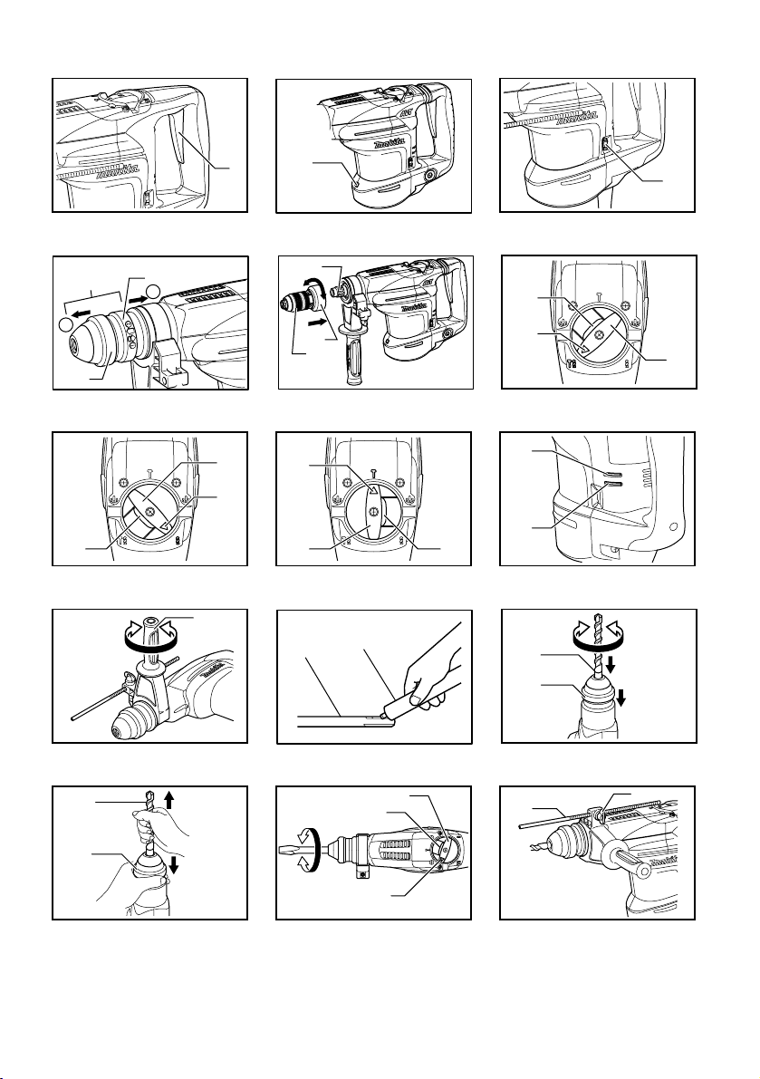
1-1. Switch trigger
2-1. Lamp
3-1. Adjusting dial
4-1. Quick change chuck for SDS-plus
4-2. Change cover
4-3. Chuck cover
5-1. Spindle
5-2. Quick change drill chuck
5-3. Change cover
6-1. Lock button
6-2. Pointer
6-3. Change lever
7-1. Lock button
7-2. Change lever
7-3. Pointer
8-1. Pointer
Explanation of general view
8-2. Change lever
8-3. Lock button
9-1. Power-ON indicator lamp (green)
9-2. Service indicator lamp (red)
10-1. Side grip
11-1. Bit shank
11-2. Bit grease
12-1. Bit
12-2. Chuck cover
13-1. Bit
13-2. Chuck cover
14-1. Change lever
14-2. Lock button
14-3. Pointer
15-1. Depth gauge
15-2. Clamp screw
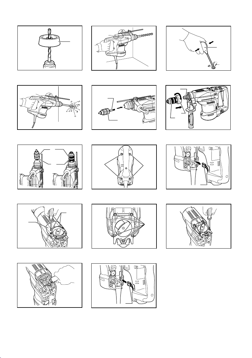
16-1. Dust cup
18-1. Blow-out bulb
20-1. Chuck adapter
20-2. Keyless drill chuck
21-1. Spindle
21-2. Quick change drill chuck
21-3. Change cover
22-1. Sleeve
22-2. Ring
23-1. Screws
24-1. Connector
25-1. Crank cap cover
25-2. Screws
26-1. Screws
29-1. Connector
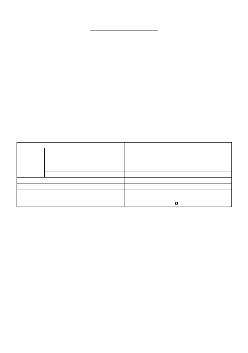
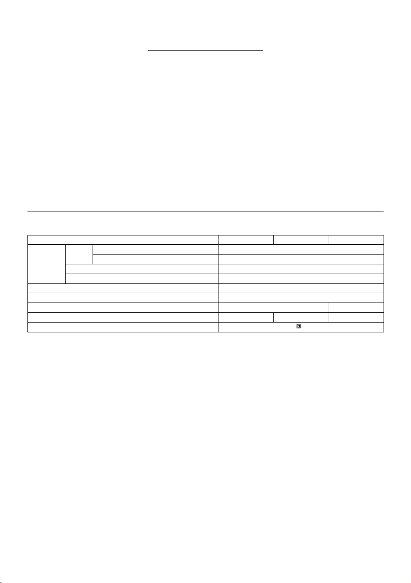
SPECIFICATIONS
Model HR3200C HR3210C HR3210FCT
Capacities
Concrete
No load speed (min-1) 315 - 630
Blows per minute 1,650 - 3,300
• Due to our continuing programme of research and development, the specifications herein are subject to change without notice.
• Specifications may differ from country to country.
• Weight according to EPTA-Procedure 01/2003
Intended use
The tool is intended for hammer drilling in brick, concrete
and stone as well as for chiselling work.
Power supply
The tool should be connected only to a power supply of
the same voltage as indicated on the nameplate, and can
only be operated on single-phase AC supply. They are
double-insulated in accordance with European Standard
and can, therefore, also be used from sockets without
earth wire.
Noise
The typical A-weighted noise level determined according
to EN60745:
Model HR3200C,HR3210C
Sound pressure level (LpA) : 89 dB(A)
Sound power level (L
Uncertainty (K) : 3 dB(A)
Tungsten-carbide tipped bit 32 mm
Core bit 90 mm
Steel 13 mm
Wood 32 mm
Overall length 398 mm 424 mm
Net weight 4.8 kg 5.2 kg 5.4 kg
Safety class /II
ENE044-1
Model HR3210FCT
Sound pressure level (LpA) : 88 dB(A)
ENF002-1
Sound power level (L
Uncertainty (K) : 3 dB(A)
) : 99 dB(A)
WA
Wear ear protection
Vibration
The vibration total value (tri-axial vector sum) determined
according to EN60745:
) : 100 dB(A)
WA
ENG905-1
Model HR3200C
Work mode : hammer drilling into concrete
Vibration emission (a
Uncertainty (K) : 1.5 m/s
) : 18.0 m/s
h,HD
2
Work mode : chiseling
Vibration emission (a
Uncertainty (K) : 1.5 m/s
h,CHeq
2
) : 12.5 m/s
2
2
4
ENG900-1
Page 5
Work mode: drilling into metal
Vibration emission (a
Uncertainty (K) : 1.5 m/s
Model HR3210C
Work mode : hammer drilling into concrete
Vibration emission (a
Uncertainty (K) : 1.5 m/s
Work mode : chiseling
Vibration emission (a
Uncertainty (K) : 1.5 m/s
) : 2.5 m/s2 or less
h,D
2
) : 10.0 m/s
h,HD
2
) : 7.5 m/s
h,CHeq
2
2
2
Work mode: drilling into metal
Vibration emission (a
Uncertainty (K) : 1.5 m/s
Model HR3210FCT
Work mode : hammer drilling into concrete
Vibration emission (a
Uncertainty (K) : 1.5 m/s
Work mode : chiseling
Vibration emission (a
Uncertainty (K) : 1.5 m/s
) : 2.5 m/s2 or less
h,D
2
) : 10.0 m/s
h,HD
2
) : 8.0 m/s
h,CHeq
2
2
2
Work mode: drilling into metal
Vibration emission (a
Uncertainty (K) : 1.5 m/s
The declared vibration emission value has been
•
) : 2.5 m/s2 or less
h,D
2
ENG901-1
measured in accordance with the standard test
method and may be used for comparing one tool
with another.
• The declared vibration emission value may also be
used in a preliminary assessment of exposure.
WARNING:
• The vibration emission during actual use of the
power tool can differ from the declared emission
value depending on the ways in which the tool is
used.
• Be sure to identify safety measures to protect the
operator that are based on an estimation of
exposure in the actual conditions of use (taking
account of all parts of the operating cycle such as
the times when the tool is switched off and when it
is running idle in addition to the trigger time).
ENH101-14
For European countries only
EC Declaration of Conformity
We Makita Corporation as the responsible
manufacturer declare that the following Makita
machine(s):
Designation of Machine:
Rotary Hammer
Model No./ Type: HR3200C,HR3210C,HR3210FCT
are of series production and
Conforms to the following European Directives:
2006/42/EC
And are manufactured in accordance with the following
standards or standardised documents:
EN60745
The technical documentation is kept by our authorised
representative in Europe who is:
Makita International Europe Ltd.
Michigan Drive, Tongwell,
Milton Keynes, MK15 8JD, England
30.1.2009
000230
Tomoyasu Kato
Director
Makita Corporation
3-11-8, Sumiyoshi-cho,
Anjo, Aichi, JAPAN
GEA010-1
General Power Tool Safety
Warnings
WARNING Read all safety warnings and all
instructions. Failure to follow the warnings and
instructions may result in electric shock, fire and/or
serious injury.
Save all warnings and instructions for
future reference.
GEB007-7
ROTARY HAMMER SAFETY
WARNINGS
1. Wear ear protectors. Exposure to noise can
cause hearing loss.
2. Use auxiliary handle(s), if supplied with the
tool. Loss of control can cause personal injury.
3. Hold power tool by insulated gripping
surfaces, when performing an operation
where the cutting accessory may contact
hidden wiring or its own cord. Cutting
accessory contacting a "live" wire may make
exposed metal parts of the power tool "live" and
could give the operator an electric shock.
4. Wear a hard hat (safety helmet), safety glasses
and/or face shield. Ordinary eye or sun
glasses are NOT safety glasses. It is also
highly recommended that you wear a dust
mask and thickly padded gloves.
5. Be sure the bit is secured in place before
operation.
6. Under normal operation, the tool is designed
to produce vibration. The screws can come
loose easily, causing a breakdown or accident.
5
Page 6
Check tightness of screws carefully before
operation.
7. In cold weather or when the tool has not been
used for a long time, let the tool warm up for a
while by operating it under no load. This will
loosen up the lubrication. Without proper
warm-up, hammering operation is difficult.
8. Always be sure you have a firm footing.
Be sure no one is below when using the tool in
high locations.
9. Hold the tool firmly with both hands.
10. Keep hands away from moving parts.
11. Do not leave the tool running. Operate the tool
only when hand-held.
12. Do not point the tool at any one in the area
when operating. The bit could fly out and
injure someone seriously.
13. Do not touch the bit or parts close to the bit
immediately after operation; they may be
extremely hot and could burn your skin.
14. Some material contains chemicals which may
be toxic. Take caution to prevent dust
inhalation and skin contact. Follow material
supplier safety data.
SAVE THESE INSTRUCTIONS.
WARNING:
DO NOT let comfort or familiarity with product
(gained from repeated use) replace strict adherence
to safety rules for the subject product. MISUSE or
failure to follow the safety rules stated in this
instruction manual may cause serious personal
injury.
FUNCTIONAL DESCRIPTION
CAUTION:
• Always be sure that the tool is switched off and
unplugged before adjusting or checking function on
the tool.
Switch action
Fig.1
CAUTION:
• Before plugging in the tool, always check to see
that the switch trigger actuates properly and returns
to the "OFF" position when released.
To start the tool, simply pull the switch trigger. Release
the switch trigger to stop.
Lighting up the lamps
For Model HR3210FCT
Fig.2
CAUTION:
• Do not look in the light or see the source of light
directly.
To turn on the lamp, pull the trigger. Release the trigger to
turn it off.
NOTE:
• Use a dry cloth to wipe the dirt off the lens of lamp.
Be careful not to scratch the lens of lamp, or it may
lower the illumination.
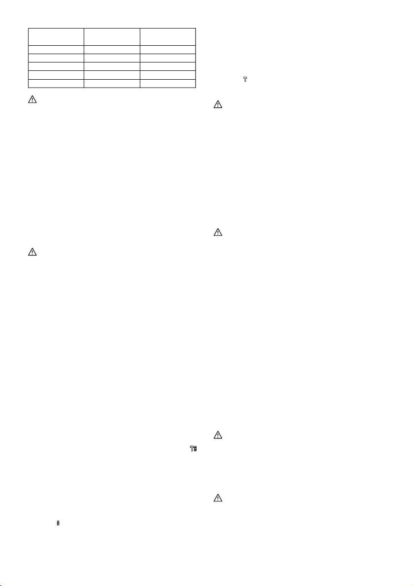
Speed change
Fig.3
The revolutions and blows per minute can be adjusted
just by turning the adjusting dial. The dial is marked 1
(lowest speed) to 5 (full speed).
Refer to the table below for the relationship between the
number settings on the adjusting dial and the
revolutions/blows per minute.
Number on
adjusting dial
008550
5
4
3
2
1
Revolutions per
minute
630
590
480
370
315
Blows per minute
3,300
3,100
2,500
1,900
1,650
CAUTION:
• If the tool is operated continuously at low speeds
for a long time, the motor will get overloaded,
resulting in tool malfunction.
• The speed adjusting dial can be turned only as far
as 5 and back to 1. Do not force it past 5 or 1, or the
speed adjusting function may no longer work.
Changing the quick change chuck for
SDS-plus
For Model HR3210FCT
The quick change chuck for SDS-plus can be easily
exchanged for the quick change drill chuck.
Removing the quick change chuck for SDS-plus
Fig.4
CAUTION:
• Before removing the quick change chuck for
SDS-plus always remove the bit.
Hold the change cover with the thumb and the middle
finger and pull it in the direction arrow 1. With the change
cover pulled in that direction, hold the chuck cover with
the index finger. While holding the chuck cover so, pull
out the quick change chuck for SDS-plus in the direction
of arrow 2 at a stroke.
Attaching the quick change drill chuck
Fig.5
Grasp the change cover and place the quick change drill
chuck on the spindle of the tool.
Make sure that the quick change drill chuck is secured by
trying to pull it several times.
6
Page 7

Selecting the action mode
Rotation with hammering
Fig.6
For drilling in concrete, masonry, etc., depress the lock
button and rotate the change lever so that the pointer
points to the
symbol. Use a tungsten-carbide tipped
bit.
Rotation only
Fig.7
For drilling in wood, metal or plastic materials, depress
the lock button and rotate the change lever so that the
pointer points to the
symbol. Use a twist drill bit or
wood bit.
Hammering only
Fig.8
For chipping, scaling or demolition operations, depress
the lock button and rotate the change lever so that the
pointer points to the
chisel, scaling chisel, etc.
symbol. Use a bull point, cold
CAUTION:
• Do not rotate the change lever when the tool is
running under load. The tool will be damaged.
• To avoid rapid wear on the mode change
mechanism, be sure that the change lever is
always positively located in one of the three action
mode positions.
Torque limiter
The torque limiter will actuate when a certain torque level
is reached. The motor will disengage from the output
shaft. When this happens, the bit will stop turning.
CAUTION:
• As soon as the torque limiter actuates, switch off
the tool immediately. This will help prevent
premature wear of the tool.
Indicator lamp
Fig.9
The green power-ON indicator lamp lights up when the
tool is plugged. If the indicator lamp does not light up, the
mains cord or the controller may be defective. The
indicator lamp is lit but the tool does not start even if the
tool is switched on, the carbon brushes may be worn out,
or the controller, the motor or the ON/OFF switch may be
defective.
The red service indicator lamp lights up when the carbon
brushes are nearly worn out to indicate that the tool
needs servicing. After approx. 8 hours of use, the motor
will automatically be shut off.
ASSEMBLY
CAUTION:
• Always be sure that the tool is switched off and
unplugged before carrying out any work on the tool.
Side grip
Fig.10
CAUTION:
• Always use the side grip to ensure operating safety
when drilling in concrete, masonry, etc.
The side grip swings around to either side, allowing easy
handling of the tool in any position. Loosen the side grip
by turning it counterclockwise, swing it to the desired
position and then tighten it by turning clockwise.
Installing or removing the bit
Fig.11
Clean the bit shank and apply bit grease before installing
the bit.
Insert the bit into the tool. Turn the bit and push it in until it
engages.
Fig.12
If the bit cannot be pushed in, remove the bit. Pull the
chuck cover down a couple of times. Then insert the bit
again. Turn the bit and push it in until it engages.
After installing, always make sure that the bit is securely
held in place by trying to pull it out.
To remove the bit, pull the chuck cover down all the way
and pull the bit out.
Fig.13
Bit angle (when chipping, scaling or
demolishing)
Fig.14
The bit can be secured at 24 different angles. To change
the bit angle, depress the lock button and rotate the
change lever so that the pointer points to the
symbol.
Turn the bit to the desired angle.
Depress the lock button and rotate the change lever so
that the pointer points to the
symbol. Then make sure
that the bit is securely held in place by turning it slightly.
Depth gauge
Fig.15
The depth gauge is convenient for drilling holes of
uniform depth. Loosen the clamp screw and adjust the
depth gauge to the desired depth. After adjusting, tighten
the clamp screw firmly.
NOTE:
• The depth gauge cannot be used at the position
where the depth gauge strikes against the gear
housing/motor housing.
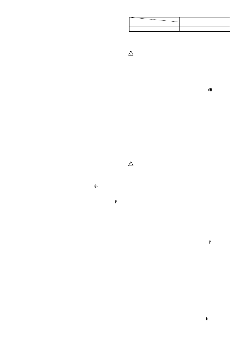
Dust cup
Fig.16
Use the dust cup to prevent dust from falling over the tool
and on yourself when performing overhead drilling
operations. Attach the dust cup to the bit as shown in the
figure. The size of bits which the dust cup can be
attached to is as follows.
7
Page 8
Bit diameter
12 mm - 16 mm
006406
Dust cup 5 6 mm - 14.5 mm
Dust cup 9
OPERATION
CAUTION:
• Always use the side grip (auxiliary handle) and
firmly hold the tool by both side grip and switch
handle during operations.
Hammer drilling operation
Fig.17
Set the change lever to the
Position the bit at the desired location for the hole, then
pull the switch trigger. Do not force the tool. Light
pressure gives best results. Keep the tool in position and
prevent it from slipping away from the hole.
Do not apply more pressure when the hole becomes
clogged with chips or particles. Instead, run the tool at an
idle, then remove the bit partially from the hole. By
repeating this several times, the hole will be cleaned out
and normal drilling may be resumed.
CAUTION:
• When the bit begins to break through concrete or if
the bit strikes reinforcing rods embedded in
concrete, the tool may react dangerously. Maintain
good balance and safe footing while holding the
tool firmly with both hands to prevent dangerous
reaction.
Blow-out bulb (optional accessory)
Fig.18
After drilling the hole, use the blow-out bulb to clean the
dust out of the hole.
Chipping/Scaling/Demolition
Fig.19
Set the change lever to the
Hold the tool firmly with both hands. Turn the tool on and
apply slight pressure on the tool so that the tool will not
bounce around, uncontrolled. Pressing very hard on the
tool will not increase the efficiency.
Drilling in wood or metal
Fig.20
Fig.21
Fig.22
For Model HR3200C,HR3210C
Use the optional drill chuck assembly. When installing it,
refer to "Installing or removing the bit" described on the
previous page.
Set the change lever so that the pointer points to
the
symbol.
symbol.
symbol.
For Model HR3210FCT
Use the quick change drill chuck as standard equipment.
When installing it, refer to "changing the quick change
chuck for SDS-plus " described on the previous page.
Hold the ring and turn the sleeve counterclockwise to
open the chuck jaws. Place the bit in the chuck as far as it
will go. Hold the ring firmly and turn the sleeve clockwise
to tighten the chuck. To remove the bit, hold the ring and
turn the sleeve counterclockwise.
Set the change lever to the
symbol.
You can drill up to 13 mm diameter in metal and up to 32
mm diameter in wood.
CAUTION:
• Never use "rotation with hammering" when the
quick change drill chuck is installed on the tool. The
quick change drill chuck may be damaged.
• Pressing excessively on the tool will not speed up
the drilling. In fact, this excessive pressure will only
serve to damage the tip of your bit, decrease the
tool performance and shorten the service life of the
tool.
• There is a tremendous twisting force exerted on the
tool/bit at the time of hole breakthrough. Hold the
tool firmly and exert care when the bit begins to
break through the workpiece.
• Always secure small workpieces in a vise or similar
hold-down device.
Diamond core drilling
When performing diamond core drilling operations,
always set the change lever to the
"rotation only" action.
position to use
CAUTION:
• If performing diamond core drilling operations using
"rotation with hammering" action, the diamond core
bit may be damaged.
MAINTENANCE
CAUTION:
• Always be sure that the tool is switched off and
unplugged before attempting to perform inspection
or maintenance.
• Never use gasoline, benzine, thinner, alcohol or the
like. Discoloration, deformation or cracks may
result.
Lubrication
CAUTION:
• This servicing should be performed by Makita
Authorized or Factory Service Centers only.
This tool requires no hourly or daily lubrication because it
has a grease-packed lubrication system. Lubricate the
tool every time the carbon brushes are replaced.
Run the tool for several minutes to warm it up. Switch off
and unplug the tool.
8
Page 9

Fig.23
Loosen the four screws and remove the handle. Note
that the top screws are different from other screws.
Fig.24
Disconnect the connector by pulling them.
Fig.25
Loosen the two screws on crank cap cover and remove
the crank cap cover.
Fig.26
Align the change lever with the symbol
, loosen the five
screws and then remove the crank cap.
Fig.27
CAUTION:
• Always remove the crank cap only after aligning the
change lever with the symbol
. Never remove it
forcibly without aligning the change lever with the
symbol
. Failure to do so does not allow
reassembling.
Fig.28
Rest the tool on the table with the bit end pointing
upwards. This will allow the old grease to collect inside
the crank housing.
Wipe out the old grease inside and replace with a fresh
grease (30 g). Use only Makita genuine hammer grease
(optional accessory). Filling with more than the specified
amount of grease (approx. 30 g) can cause faulty
hammering action or tool failure. Fill only with the
specified amount of grease.
CAUTION:
• Be careful not to damage the connector or lead
wires especially when wiping out the old grease.
To reassemble the tool, follow the disassembling
procedure in reverse.
CAUTION:
• Do not tighten the crank cap excessively. It is made
of resin and is subject to breakage.
Fig.29
Connect the connector firmly and then reinstall the
handle.
CAUTION:
• Be careful not to damage the connector or lead
wires especially when installing the handle.
To maintain product SAFETY and RELIABILITY, repairs,
carbon brush inspection and replacement, any other
maintenance or adjustment should be performed by
Makita Authorized Service Centers, always using Makita
replacement parts.
ACCESSORIES
CAUTION:
• These accessories or attachments are
recommended for use with your Makita tool
specified in this manual. The use of any other
accessories or attachments might present a risk of
injury to persons. Only use accessory or
attachment for its stated purpose.
If you need any assistance for more details regarding
these accessories, ask your local Makita Service Center.
• SDS-Plus Carbide-tipped bits
• Bull point
• Core bit
• Cold chisel
• Diamond core bit
• Hammer grease
• Scaling chisel
• Grooving chisel
• Drill chuck assembly
• Drill chuck S13
• Chuck adapter
• Chuck key S13
• Bit grease
• Side grip
• Depth gauge
• Blow-out bulb
• Dust cup
• Safety goggles
• Plastic carrying case
9
Page 10
УКРАЇНСЬКА (Оригінальні інструкції)
1-1. Кнопка вимикача
2-1. Ліхтар
3-1. Диск для регулювання
4-1. Швидкороз'ємний патрон для
SDS-plus
4-2. Змінна кришка
4-3. Кришка патрона
5-1. Шпиндель
5-2. Швидкорознімний патрон
5-3. Змінна кришка
6-1. Фіксатор
6-2. Покажчик
6-3. Важіль перемикання
7-1. Фіксатор
7-2. Важіль перемикання
7-3. Покажчик
8-1. Покажчик
Пояснення до загального виду
8-2. Важіль перемикання
8-3. Фіксатор
9-1. Лампочка індикатора ВМК.
(зелена)
9-2. Службова лампочка індикатора
(червона)
10-1. Бокова рукоятка
11- 1. Потилиця свердла
11- 2. Мастило для свердла
12-1. Свердло
12-2. Кришка патрона
13-1. Свердло
13-2. Кришка патрона
14-1. Важіль перемикання
14-2. Фіксатор
14-3. Покажчик
15-1. Обмежувач глибини
15-2. Затискний гвинт
16-1. Пилозахисний ковпачок
18-1. Продувна колба
20-1. Адаптер патрона
20-2. Патрон свердла, що не потребує
ключа
21-1. Шпиндель
21-2. Швидкорознімний патрон
21-3. Змінна кришка
22-1. Муфта
22-2. Кільце
23-1. Гвинти
24-1. Роз'єм
25-1. Кришка ковпачка кривошипа
25-2. Гвинти
26-1. Гвинти
29-1. Роз'єм
ТЕХНІЧНІ ХАРАКТЕРИСТИКИ
Модель HR3200C HR3210C HR3210FCT
Свердло із наконечником з
Діаметр
свердління
• Через те що ми не припиняємо програми досліджень і розвитку наведені тут технічні характеристики можуть бути змінені
без попередження.
• У різних країнах технічні характеристики можуть бути різними.
• Вага відповідно до EPTA-Procedure 01/2003
Бетон
Швидкість холостого ходу (хв.-1) 315 - 630
Ударів за хвилину 1650 - 3300
Загальна довжина 398 мм 424 мм
Чиста вага 4,8 кг 5,2 кг 5,4 кг
Клас безпеки /II
Призначення
Інструмент призначено для ударного свердління
цегли, бетону та каміння, а також довбання.
Джерело живлення
Інструмент можна підключати лише до джерела
струму, що має напругу, зазначену в табличці з
заводськими характеристиками, і він може працювати
лише від однофазного джерела перемінного струму.
Інструмент має подвійну ізоляцію згідно з
європейським стандартом і, отже, може підключатися
до розеток без клеми заземлення.
Шум
Рівень шуму за шкалою А у типовому виконанні,
визначений відповідно до EN60745:
карбіду вольфраму
Колонкове свердло 90 мм
Сталь 13 мм
Деревина 32 мм
ENE044-1
Модель HR3200C,HR3210C
Рівень звукового тиску (LpA): 89 дБ(A)
ENF002-1
Рівень акустичної потужності (L
Похибка (K) : 3 дБ(A)
Модель HR3210FCT
Рівень звукового тиску (LpA): 88 дБ(A)
Рівень акустичної потужності (L
Похибка (K) : 3 дБ(A)
Користуйтеся засобами захисту слуху
ENG905-1
Вібрація
Загальна величина вібрації (сума трьох векторів)
визначена згідно з EN60745:
10
32 мм
): 100 дБ(A)
WA
): 99 дБ(A)
WA
ENG900-1
Page 11
Модель HR3200C
Режим роботи: свердління бетону
Вібрація (a
Похибка (К): 1,5 м/с
) : 18,0 м/с
h,HD
Режим роботи: довбання
Вібрація (a
Похибка (К): 1,5 м/с
год,CHeq
2
2
) : 12,5 м/с
2
2
Режим роботи: свердління металу
Вібрація (a
Похибка (К): 1,5 м/с
) : 2,5 м/с2 або менше
год,D
2
Модель HR3210C
Режим роботи: свердління бетону
Вібрація (a
Похибка (К): 1,5 м/с
) : 10,0 м/с
h,HD
Режим роботи: довбання
Вібрація (a
Похибка (К): 1,5 м/с
год,CHeq
2
) : 7,5 м/с
2
2
2
Режим роботи: свердління металу
Вібрація (a
Похибка (К): 1,5 м/с
) : 2,5 м/с2 або менше
год,D
2
Модель HR3210FCT
Режим роботи: свердління бетону
Вібрація (a
Похибка (К): 1,5 м/с
) : 10,0 м/с
h,HD
Режим роботи: довбання
Вібрація (a
Похибка (К): 1,5 м/с
год,CHeq
2
) : 8,0 м/с
2
2
2
Режим роботи: свердління металу
Вібрація (a
Похибка (К): 1,5 м/с
Заявлене значення вібрації було виміряно у
•
) : 2,5 м/с2 або менше
год,D
2
ENG901-1
відповідності до стандартних методів
тестування та може використовуватися для
порівняння одного інструмента з іншим.
• Заявлене значення вібрації може також
використовуватися для попередньої оцінки
впливу.
УВАГА:
• Залежно від умов використання вібрація під час
фактичної роботи інструмента може
відрізнятися від заявленого значення вібрації.
• Забезпечте належні запобіжні заходи для
захисту оператора, що відповідатимуть умовам
використання інструмента (слід брати до уваги
всі складові робочого циклу, такі як час, коли
інструмент вимкнено та коли він починає
працювати на холостому ході під час запуску).
Тільки для країн Європи
Декларація про відповідність стандартам
ЄС
Наша компанія, Makita Corporation, як
відповідальний виробник, наголошує на тому, що
обладнання Makita:
Позначення обладнання:
Перфоратор
№ моделі/ тип: HR3200C,HR3210C,HR3210FCT
є серійним виробництвом та
Відповідає таким Європейським Директивам:
2006/42/EC
Та вироблені у відповідності до таких стандартів та
стандартизованих документів:
EN60745
Технічн а документація знаходиться у нашого
уповноваженого представника в Європі, а саме:
Makita International Europe Ltd.
Michigan Drive, Tongwell,
Milton Keynes, MK15 8JD, Англія
30.1.2009
000230
Том оязу Като
Директор
Makita Corporation
3-11-8, Sumiyoshi-cho,
Anjo, Aichi, ЯПОНІЯ
Застереження стосовно техніки
безпеки при роботі з
електроприладами
УВАГА! Прочитайте усі застереження
стосовно техніки безпеки та всі інструкції.
Недотримання даних застережень та інструкцій може
призвести до ураження струмом та виникнення
пожежі та/або серйозних травм.
Збережіть усі інструкції з техніки
безпеки та експлуатації на майбутнє.
ПОПЕРЕДЖЕННЯ ПРО
НЕБЕЗПЕКУ ПІД ЧАС РОБОТИ З
ПЕРФОРАТОРОМ
1. Слід одягати захисні навушники.
Незахищеність від шуму може спричинити до
втрати слуху.
2. Використовуйте допоміжну(і) ручку(и), якщо
вона(и) поставляються разом з
інструментом. Втрата контролю може
ENH101-14
GEA010-1
GEB007-7
11
Page 12

призвести до травм.
3. Тримайте електроприлад за ізольовані
поверхні держака під час виконання дії, за
якої він може зачепити сховану
електропроводку або власний шнур.
Торкання ріжучим приладом струмоведучої
проводки може призвести до передання
напруги до оголених металевих частин
інструмента та ураженню оператора
електричним струмом.
4. Слід одягати каску (захисний шолом),
захисні
окуляри та/або щиток-маску.
Звичайні окуляри або темні окулярі для
захисту від сонця НЕ Є захисними
окулярами. Настійно рекомендовано
одягати пилозахисну маску та щільно
набиті рукавиці.
5. Перед початком роботи обов'язково
перевірте, щоб полотно було надійно
закріплене в робочому положенні.
6. При нормальній роботі інструмент вібрує.
Гвинти можуть швидко
розбовтатися, що
призведе до поломки або поранення. Перед
початком роботи слід перевірити міцність
затягування гвинтів.
7. Під час холодної погоди або якщо
інструмент не використовувався довгий час,
його слід розігріти, давши попрацювати
якийсь час на холостому ході. Це
розм'якшить мастило. Якщо не провести
розігрів, забивання буде важким.
8. Завжди майте тверду
опору.
При виконанні висотних робіт
переконайтеся, що під Вами нікого немає.
9. Міцно тримай інструмент обома руками.
10. Тримай руки на відстані від рухомих частин.
11. Не залишайте інструмент працюючим.
Працюйте з інструментом тільки тоді, коли
тримаєте його в руках.
12. Під час роботи ніколи не спрямовуй
інструмент на людину, що знаходиться
поруч з місцем роботи. Полотно може
вискочити та завдати серйозної травми.
13. Не слід торкатися полотна або частин, що
примикають до нього, одразу після різання,
вони можуть бути дуже гарячими та
призвести до опіку шкіри.
14. Деякі матеріали мають у своєму складі
токсичні хімічні речовини. Будьте уважні,
щоб запобігти вдихання пилу та
контактів зі
шкірою. Дотримуйтеся правил техніки
безпеки виробника матеріалу .
ЗБЕРІГАЙТЕ ЦІ ВКАЗІВКИ
УВАГА:
НІКОЛИ НЕ СЛІД втрачати пильності та
розслаблюватися під час користування виробом
(що приходить при частому використанні); слід
завжди строго дотримуватися правил безпеки під
час використання цього пристрою. НЕНАЛЕЖНЕ
ВИКОРИСТАННЯ або недотримання правил
безпеки, викладених в цьому документі, може
призвести до серйозних травм.
ІНСТРУКЦІЯ З ВИКОРИСТАННЯ
ОБЕРЕЖНО:
• Перед регулюванням та перевіркою справності
інструменту, переконайтеся в тому, що він
вимкнений та відключений від мережі.
Дія вимикача.
Fig.1
ОБЕРЕЖНО:
• Перед вмиканням інструменту у мережу
обов'язково перевірте, чи кнопка вимикача
нормально спрацьовує і після відпускання
повертається в положення "вимкнено".
Для того, щоб запустити інструмент, слід просто
натиснути на курок вмикача. Для зупинення роботи
курок слід відпустити.
Увімкнення підсвітки
Для моделі HR3210FCT
Fig.2
ОБЕРЕЖНО:
• Не дивіться на світло або безпосередньо на
джерело світла.
Для того, щоб увімкнути підсвічування, натисніть
курок вмикача. Для вимкнення підсвічування
відпустіть курок.
ПРИМІТКА:
• Для видалення бруду з лінзи підсвітки
користуйтесь сухою тканиною. Будьте обережні,
щоб не подряпати лінзу підсвітки, тому що
можна погіршити освітлювання.
Зміна швидкості
Fig.3
Кількість оберті та ударів за хвилину можна
регулювати просто повертаючи диск регулювання.
Диск пронумерований від 1 (найнижча швидкість) до 5
(найвища швидкість).
Співвідношення між номером налаштування на диску
та кількістю обертів/ударів за хвилину - див. таблицю
нижче.
12
Page 13
Номер на регулюючому
диску
5
4
3
2
1
008550
Обертів за хвилину Ударів за хвилину
630
590
480
370
315
3300
3100
2500
1900
1650
ОБЕРЕЖНО:
• Якщо інструмент протягом тривалого часу
безперервно експлуатується на низький
швидкості, мотор перевантажується. що
призводить до порушень в роботі інструмента.
• Диск регулювання швидкості можна повертати
тільки від 1 до 5 та назад. Не намагайтесь
повернути його силою за межу 1 або 5, бо це
може зламати функцію регулювання.
Заміна швидкороз'ємного патрона для
SDS-plus
Для моделі HR3210FCT
Швидкороз'ємний патрон для SDS-plus можна легко
замінити на швидкороз'ємний патрон для свердел.
Зняття швидкороз'ємного патрона для SDS-plus
Fig.4
ОБЕРЕЖНО:
• Перед зняттям швидкороз'ємного патрона для
SDS-plus слід завжди знімати свердло.
Візьміться за кришку патрона великим та середнім
пальцем та потягніть у напрямку стрілки 1. Коли
кришку встановлено в цю позицію, утримуйте її
вказівним пальцем. Утримуючи так кришку, витягніть
швидкороз'ємний патрон для SDS-plus у напрямку
стрілки 2 одним рухом.
Встановлення швидкороз'ємного патрона
для
свердел
Fig.5
Візьміться за кришку патрона та встановіть
швидкороз'ємний патрон на шпиндель інструменту.
Переконайтесь, що швидкороз'ємний патрон
встановлено вірно, потягнувши його декілька разів.
Вибір режиму роботи
Обертання із відбиванням
Fig.6
Для свердлення бетону, кладки та ін. слід віджати
кнопку блокування та повернути важіль перемикання
таким чином, щоб покажчик вказував на символ
Слід використовувати свердло із наконечником з
карбіду вольфраму.
Тільки обертання
Fig.7
Для свердлення дерева, метала або пластика слід
віджати кнопку блокування та повернути важіль
перемикання таким чином, щоб покажчик вказував на
символ
свердло для деревини.
. Слід використовувати вите свердло або
Тільки биття
Fig.8
Для операцій з довбання, шкребіння або демонтажу,
слід віджати кнопку блокування та повернути важіль
перемикання таким чином, щоб покажчик вказував на
символ
слюсарне зубило, зубило для шкребіння та ін.
. Використовуйте пірамідальне долото,
ОБЕРЕЖНО:
• Неможна повертати важіль перемикання, коли
інструмент працює під навантаженням.
Інструмент може пошкодитись.
• Для запобігання швидкому зносові механізму
зміни режиму, слід перевіряти, щоб важіль
завжди був переключений на один з трьох
режимів роботи.
Обмежувач моменту
Обмежувач моменту спрацьовує, коли досягнуто
момент певної величини. Мотор відключить
зчеплення із вихідним валом. Коли це трапляється
свердло перестає обертатись.
ОБЕРЕЖНО:
• Як тільки спрацював обмежувач моменту,
інструмент слід негайно вимкнути. Це допоможе
запобігти передчасному зносу інструмента.
Лампочка індикатора
Fig.9
Коли інструмент вмикають до сіті, загоряється зелена
індикаторна лампочка. Якщо лампочка індикатора не
загоряється, то шнур живлення або контролер
можуть бути дефектними. Якщо індикаторна лампа
горить, але інструмент не запускається, навіть якщо
він увімкнений, то це може означати, що зношені
графітові щітки, є дефект в контролері, моторі або у
вмикачеві.
Червона лампочка індикатора загоряється, коли
графітові щітки майже зношені, щоб показати, що
інструмент потребує обслуговування. Після
приблизно 8 годин роботи інструмент автоматично
відключиться.
КОМПЛЕКТУВАННЯ
ОБЕРЕЖНО:
• Перед тим, як зайнятись комплектуванням
.
інструменту, переконайтеся в тому, що він
вимкнений та відключений від мережі.
Бокова ручка
Fig.10
ОБЕРЕЖНО:
• Для безпеки роботи слід завжди
використовувати бокову ручку під час
свердління бетону, кладки та ін.
13
Page 14
Бокову ручку можна пересунути на будь-яку сторону,
що забезпечує зручність експлуатації інструмента в
будь-якому положенні. Послабте бокову ручку,
повернувши її проти годинникової стрілки, пересуньте
її в необхідне положення, а потім затягніть її,
повернувши по годинниковій стрілці.
Встановлення та зняття долота
Fig.11
Перед встановленням долота слід вичистити
потилицю долота та змастити її.
Вставте долото в інструмент. Проверніть долото та
просуньте його, доки воно не стане на місце.
Fig.12
Якщо долото не вставляється, його слід зняти. Пару
разів потягніть вниз кришку патрона. Потім знову
вставте долото. Проверніть долото та просуньте його,
доки воно не
стане на місце.
Після встановлення слід перевірити, щоб долото
було надійно вставлено, спробувавши витягнути
його.
Для зняття долота слід до упора потягнути вниз
кришку патрона та витягти свердло.
Fig.13
Кут долота (під час довбання, шкребіння
або демонтажу)
Fig.14
Cвердло можна закріпити під 24 різними кутами. Для
зміни кута свердла слід натиснути на кнопку
блокування та повернути важіль перемикання таким
чином, щоб покажчик вказував на мітку
. Поверніть
свердло на необхідний кут.
Натисніть на кнопку блокування та поверніть важіль
перемикання, щоб покажчик вказував на мітку
Потім перевірте, щоб долото або зубило було надійно
встановлене, злегка повернувши його.
Обмежувач глибини
Fig.15
Глибиномір є зручним для свердління отворів
однакової глибини. Послабте затискний гвинт та
відрегулюйте глибиномір на необхідну глибину. Після
регулювання затягніть затискний гвинт.
ПРИМІТКА:
• Глибиномір неможна використовувати у
положеннях, коли він б'ється об корпус
механізму або мотора.
Пилозахисний ковпачок
Fig.16
Використовуйте пилозахисний ковпачок для
запобігання падінню пилу на інструмент та на себе
під час свердління. Встановіть пилозахисний
ковпачок на свердло, як показано на малюнку.
Розміри свердел, на які можна встановлювати
пилозахисний ковпачок такі.
Пилозахисний ковпачок 5 6 мм - 14,5 мм
Пилозахисний ковпачок 9 12 мм - 16 мм
006406
Діаметр свердла
ЗАСТОСУВАННЯ
ОБЕРЕЖНО:
• Слід завжди використовувати бокову ручку
(додаткова ручка) та міцно тримати інструмент
за бокову ручку та ручку вмикача під час роботи.
Робота перфоратора
Fig.17
Встановіть важіль перемикання на мітку
Поставте свердло в місце, де необхідно зробити отвір,
а потім натисніть на курок вмикача. Не треба
прикладати силу до інструмента. Невеликий тиск
забезпечує найліпші результати. Тримайте інструмент
в належному положенні, та не давайте йому
вискочити з отвору.
Коли отвір засмічується обломками або частками, не
треба прикладати більший тиск. Замість цього
прокрутити інструмент на холостому ходу, а потім
частково витягнути інструмент з отвору. Якщо це
зробити декілька разів, отвір очиститься, і нормальне
свердлення можна поновити.
ОБЕРЕЖНО:
• Коли свердло починає пробиватись через бетон,
або якщо свердло вдаряється в закладену в
бетон арматуру, інструмент може небезпечно
повести себе. Для того, щоб запобігти
небезпечній реакції, слід стійко стояти на ногах
.
та міцно тримати інструмент обома руками.
Продувна колба (додаткова приналежність)
Fig.18
Після того, як отвір був просвердлений, продувна
колба вичищає пил з отвору.
Довбання/Шкребіння/Демонтаж
Fig.19
Встановіть важіль перемикання на мітку
Інструмент слід міцно тримати обома руками.
Увімкніть інструмент та злегка натисніть на інструмент,
щоб він безконтрольно не хитався. Сильне
натискання на інструмент не поліпшує ефективності.
Свердлення деревини або металу.
Fig.20
Fig.21
Fig.22
Для моделей HR3200C, HR3210C
Використовуйте додатковий вузол патрона. Під час
встановлення - див. розділ "Встановлення та зняття
свердла", наведений на попередній сторінці.
Виставте важіль перемикання на мітку
.
.
слід
.
14
Page 15

Для моделі HR3210FCT
У якості стандартного обладнання слід
використовувати швидкороз'ємний патрон. Під час
встановлення - див. розділ "заміна швидкороз'ємного
патрона для SDS-plus", наведений на попередній
сторінці.
Утримуйте кільце та поверніть муфту проти
годинникової стрілки для того, щоб відкрити кулачки
патрона. Вставте свердло або викрутку до упора.
Міцно утримуйте кільце та поверніть
муфту по
годинниковій стрілці для того, щоб затягнути кулачки
патрона. Для того, щоб зняти свердло, утримуйте
кільце та поверніть муфту проти годинникової
стрілки.
Встановіть важіль перемикання на символ
.
Діаметр свердління може бути до 13 мм в металі та до
32 мм в деревині.
ОБЕРЕЖНО:
• Коли на інструменті встановлений вузол
швидкороз'ємного свердлильного патрона, не
можна користуватись режимом "свердління із
відбиванням". Це може ушкодити
швидкороз'ємний патрон.
• Надмірний тиск на інструмент не пришвидшує
свердління. Насправді надмірний тиск може
лише пошкодити свердло, зменшити
продуктивність інструменту та вкоротити термін
його експлуатації.
• У момент завершення наскрізного отвору на
інструмент, або свердло діє надзвичайно
велике скручувальне зусилля. Міцно тримайте
інструмент і будьте обережні, коли свердло
починає виходити із протилежного боку
заготовки.
• Невелику заготовку слід затискувати в лещата
або подібний пристрій.
Свердлення алмазним свердлом
Під час свердління алмазним свердлом слід завжди
пересувати важіль перемикання в положення
щоб задіяти режим "тільки обертання".
ОБЕРЕЖНО:
• Якщо свердління виконується алмазним
свердлом в режимі "обертання із відбиванням",
свердло може бути пошкоджено.
ТЕХНІЧНЕ ОБСЛУГОВУВАННЯ
ОБЕРЕЖНО:
• Перед тим, як оглянути інструмент, або виконати
ремонт, переконайтеся, що він вимкнений та
відключений від мережі.
• Ніколи не використовуйте газолін, бензин,
розріджувач, спирт та подібні речовини. Їх
використання може призвести до зміни кольору,
деформації та появи тріщин.
Змащування
ОБЕРЕЖНО:
• Цей вид обслуговування повинен виконуватись
тільки уповноваженими сервісними центрами
Makita або заводськими сервісними центрами.
Інструмент не потребує щоденного або щоденного
змащування, тому що він обладнаний заповненою
мастилом системою змащування. Змащуйте
інструмент кожного разу, коли замінюєте графітові
щітки.
Прокрутіть інструмент декілька разів. щоб його
розігріти. Вимкніть інструмент та відключіть його від
сіті.
Fig.23
Послабте чотири гвинта та зніміть ручку. Майте на
увазі, що верхні гвинти відрізняються від решти
гвинтів.
Fig.24
Від'єднайте роз'єм, потягнувши за них.
Fig.25
Відкрутіть дві гайки кришки ковпачка кривошипа та
зніміть кришку.
Fig.26
Перемкніть важіль на символ
, відкрутіть п'ять
гайок та зніміть ковпачок кривошипа.
Fig.27
ОБЕРЕЖНО:
• Знімати ковпачок кривошипа можна лише тоді,
коли важіль вказує на символ
намагайтесь силою зняти ковпачок, поки важіль
не буде встановлено на символ
завадити подальшому збиранню інструмента.
Fig.28
Обіпріть інструмент на стіл свердлом догори. Це
дасть можливість старому мастилу зібратись
всередині корпуса кривошипа.
Зітріть старе мастило всередині та замініть його на
,
свіже (30 г). Використовуйте тільки оригінальне
мастило для перфораторів Makita (додаткова
приналежність). Якщо залити більше, ніж вказана
кількість мастила (біля 30 г), це може
призвести до
дефектів в роботі або поломки інструмента. Заливати
слід тільки вказану кількість мастила.
ОБЕРЕЖНО:
• Слід бути обережним, щоб не пошкодити роз'єм
або виводи, особливо під час витирання старого
мастила.
Для збирання інструменту виконуйте процедуру його
розбирання у зворотному порядку.
ОБЕРЕЖНО:
• Не затягуйте надмірно ковпачок кривошипа. Він
зроблений із полімеру та може зламатись.
. Не
. Це може
15
Page 16

Fig.29
Щільно приєднайте роз'єм та встановіть ручку на
місце.
ОБЕРЕЖНО:
• Слід бути обережним, щоб не пошкодити роз'єм
або виводи, особливо під час встановлення
ручки.
Для того, щоб підтримувати БЕЗПЕКУ та
НАДІЙНІСТЬ, ремонт, огляд та заміну вугільних щіток,
будь-яке інше технічне обслуговування або
регулювання мають виконувати уповноважені центри
обслуговування "Макіта", де використовуються лише
стандартні запчастини "Макіта".
ОСНАЩЕННЯ
ОБЕРЕЖНО:
• Це оснащення або приладдя рекомендовано
для використання з інструментами "Макіта", що
описані в інструкції з експлуатації. Використання
якогось іншого оснащення або приладдя може
спричинити травмування. Оснащення або
приладдя слід використовувати лише за
призначенням.
У разі необхідності, отримати допомогу в більш
детальному ознайомленні з оснащенням звертайтесь
до місцевого Сервісного центру "Макіта".
• Свердла SDS-Plus із твердосплавним
наконечником
• Пірамідальне долото
• Колонкове свердло
• Слюсарне зубило
• Свердло із алмазним сердечником
• Мастило для перфоратора
• Зубило для довбання
• Канавкове долото
• Вузол патрона свердла
• Патрон S13
• Адаптер патрона
• Ключ для патрона S13
• Мастило для свердла
• Бокова ручка
• Обмежувач глибини
• Продувна колба
• Пилозахисний ковпачок
• Захисні окуляри
• Пластмасова валіза для транспортування
16
Page 17
POLSKI (Oryginalna instrukcja)
1-1. Spust przełącznika
2-1. Lampka
3-1. Pokrętło regulacyjne
4-1. Szybkowymienny uchwyt do
końcówek SDS-plus
4-2. Pierścień wymiany
4-3. Osłona uchwytu
5-1. Wrzeciono
5-2. Szybkowymienny uchwyt wiertarski
5-3. Pierścień wymiany
6-1. Przycisk blokujący
6-2. Wskaźnik
6-3. Dźwignia zmiany trybu pracy
7-1. Przycisk blokujący
7-2. Dźwignia zmiany trybu pracy
7-3. Wskaźnik
8-1. Wskaźnik
Objaśnienia do widoku ogólnego
8-2. Dźwignia zmiany trybu pracy
8-3. Przycisk blokujący
9-1. Kontrolka zasilania (zielona)
9-2. Kontrolka przeglądu (czerwona)
10-1. Uchwyt boczny
11-1. Trzon wiertła
11-2. Smar do wierteł
12-1. Wiertło
12-2. Osłona uchwytu
13-1. Wiertło
13-2. Osłona uchwytu
14-1. Dźwignia zmiany trybu pracy
14-2. Przycisk blokujący
14-3. Wskaźnik
15-1. Ogranicznik głębokości
15-2. Śruba zaciskowa
16-1. Osłona przeciwpyłowa
18-1. Gruszka do przedmuchiwania
20-1. Przejściówka uchwytu
20-2. Uchwyt bez klucza
21-1. Wrzeciono
21-2. Szybkowymienny uchwyt
wiertarski
21-3. Pierścień wymiany
22-1. Tuleja
22-2. Pierścień
23-1. Wkręty
24-1. Złączka
25-1. Osłona korka mechanizmu
korbowego
25-2. Wkręty
26-1. Wkręty
29-1. Złączka
SPECYFIAKCJE
Model HR3200C HR3210C HR3210FCT
Wiertło udarowe z końcówką z węglika wolframu
Wydajność
• W związku ze stale prowadzonym przez naszą firmę programem badawczo-rozwojowym, niniejsze specyfikacje mogą ulec zmianom
bez wcześniejszego powiadomienia.
• Specyfikacje mogą różnić się w zależności od kraju.
• Waga obliczona zgodnie z procedurą EPTA 01/2003
Beton
Prędkość bez obciążenia (min-1) 315 - 630
Liczba udarów na minutę 1 650 - 3 300
Długość całkowita 398 mm 424 mm
Klasa bezpieczeństwa /II
Przeznaczenie
Narzędzie to jest przeznaczone do wiercenia udarowego
w cegle, betonie i kamieniu, a także do dłutowania.
Zasilanie
Elektronarzędzie może być podłączane jedynie do
zasilania o takim samym napięciu jakie określa tabliczka
znamionowa i może być uruchamiane wyłącznie przy
zasilaniu jednofazowym prądem zmiennym. Przewody
są podwójnie izolowane zgodnie z Normami
Europejskimi i dlatego mogą być podłączone do
gniazdek bez przewodu uziemiającego.
Końcówka rdzenia 90 mm
Stal 13 mm
Drewno 32 mm
Ciężar netto 4,8 kg 5,2 kg 5,4 kg
ENE044-1
Model HR3200C,HR3210C
Poziom ciśnienia akustycznego (LpA): 89 dB(A)
ENF002-1
Poziom mocy akustycznejl (L
Niepewność (K): 3 dB(A)
Model HR3210FCT
Poziom ciśnienia akustycznego (LpA): 88 dB(A)
Poziom mocy akustycznejl (L
Niepewność (K): 3 dB(A)
ENG905-1
Należy stosować ochraniacze na uszy
Poziom hałasu i drgań
Typowy równoważny poziom dźwięku A określony w
oparciu o EN60745:
Drgania
Całkowita wartość poziomu drgań (suma wektorów w 3
osiach) określona zgodnie z normą EN60745:
17
32 mm
): 100 dB(A)
WA
): 99 dB(A)
WA
ENG900-1
Page 18
Model HR3200C
Tryb pracy: wiercenie udarowe w betonie
Emisja drgań (a
Niepewność (K) : 1,5 m/s
) : 18,0 m/s
h,HD
Tryb pracy: dłutowanie
Emisja drgań (a
Niepewność (K) : 1,5 m/s
h,CHeq
2
): 12,5 m/s
2
2
2
Tryb pracy: wiercenie w metalu
Emisja drgań (a
Niepewność (K) : 1,5 m/s
) : 2,5 m/s2 lub poniżej
h,D
2
Model HR3210C
Tryb pracy: wiercenie udarowe w betonie
Emisja drgań (a
Niepewność (K) : 1,5 m/s
) : 10,0 m/s
h,HD
Tryb pracy: dłutowanie
Emisja drgań (a
Niepewność (K) : 1,5 m/s
h,CHeq
2
): 7,5 m/s
2
2
2
Tryb pracy: wiercenie w metalu
Emisja drgań (a
Niepewność (K) : 1,5 m/s
) : 2,5 m/s2 lub poniżej
h,D
2
Model HR3210FCT
Tryb pracy: wiercenie udarowe w betonie
Emisja drgań (a
Niepewność (K) : 1,5 m/s
) : 10,0 m/s
h,HD
Tryb pracy: dłutowanie
Emisja drgań (a
Niepewność (K) : 1,5 m/s
h,CHeq
2
): 8,0 m/s
2
2
2
Tryb pracy: wiercenie w metalu
Emisja drgań (a
Niepewność (K) : 1,5 m/s
Deklarowana wartość wytwarzanych drgań została
•
) : 2,5 m/s2 lub poniżej
h,D
2
ENG901-1
zmierzona zgodnie ze standardową metodą
testową i można ją wykorzystać do porównywania
narzędzi.
• Deklarowaną wartość wytwarzanych drgań można
także wykorzystać we wstępnej ocenie narażenia.
OSTRZEŻENIE:
• Drgania wytwarzane podczas rzeczywistego
użytkowania elektronarzędzia mogą się różnić od
wartości deklarowanej, w zależności od sposobu
jego użytkowania.
• W oparciu o szacowane narażenie w rzeczywistych
warunkach użytkowania należy określić środki
bezpieczeństwa w celu ochrony operatora
(uwzględniając wszystkie elementy cyklu działania,
tj. czas, kiedy narzędzie jest wyłączone i kiedy
pracuje na biegu jałowym, a także czas, kiedy jest
włączone).
Dotyczy tylko krajów europejskich
ENH101-14
Deklaracja zgodności UE
Niniejszym firma Makita Corporation jako
odpowiedzialny producent oświadcza, iż opisywane
urządzenie marki Makita:
Opis maszyny:
Wiertarka udarowa
Model nr/ Typ: HR3200C,HR3210C,HR3210FCT
jest produkowane seryjnie oraz
jest zgodne z wymogami określonymi w
następujących dyrektywach europejskich:
2006/42/EC
Jest produkowane zgodnie z następującymi normami lub
dokumentami normalizacyjnymi:
EN60745
Dokumentacja techniczna przechowywana jest przez
naszego autoryzowanego przedstawiciela na Europę,
którym jest:
Makita International Europe Ltd.
Michigan Drive, Tongwell,
Milton Keynes, MK15 8JD, Anglia
30.1.2009
000230
Tomoyasu Kato
Dyrektor
Makita Corporation
3-11-8, Sumiyoshi-cho,
Anjo, Aichi, JAPONIA
Ogólne zasady bezpieczeństwa
obsługi elektronarzędzi
OSTRZEŻENIE Przeczytaj wszystkie ostrzeżenia
i instrukcje. Nie przestrzeganie ich może prowadzić do
porażeń prądem, pożarów i/lub poważnych obrażeń
ciała.
Wszystkie ostrzeżenia i instrukcje należy
zachować do późniejszego
wykorzystania.
OSTRZEŻENIE DOTYCZĄCE
BEZPIECZEŃSTWA WIERTARKI
UDAROWEJ
1. Noś ochraniacze na uszy. Hałas może
spowodować utratę słuchu.
2. Używać narzędzia z dostarczonymi uchwytami
pomocniczymi. Utrata kontroli może
spowodować obrażenia.
18
GEA010-1
GEB007-7
Page 19

3. Gdy narzędzie tnące podczas pracy może
zetknąć się z ukrytymi przewodami
elektrycznymi bądź własnym przewodem
zasilającym, należy trzymać urządzenie za
izolowane uchwyty. Przecięcie przewodu
elektrycznego pod napięciem powoduje, że
również odsłonięte elementy metalowe narzędzia
znajdą się pod napięciem, grożąc porażeniem
operatora prądem elektrycznym.
4. Noś kask, okulary ochronne oraz/lub osłonę
twarzy. Zwykłe okulary bądź okulary
przeciwsłoneczne NIE są okularami
ochronnymi. Stanowczo zaleca się również
zakładanie maski przeciwpyłowej oraz
grubych rękawic.
5. Przed uruchomieniem narzędzia należy si
ę
upewnić, czy końcówka jest dobrze
zamocowana w uchwycie.
6. W normalnych warunkach pracy narzędzie
wytwarza drgania. W związku z tym śruby
mogą łatwo ulec poluzowaniu, doprowadzając
do awarii lub wypadku. Przed uruchomieniem
narzędzia należy skontrolować, czy śruby są
dobrze dokręcone.
7. W przypadku niskiej temperatury lub gdy
narzędzie nie było używane przez dłuższy czas,
należy najpierw rozgrzać narzędzie
uruchamiając je na chwilę bez obciążenia. W
ten sposób gęstość smaru ulegnie
zmniejszeniu. Bez właściwego rozgrzania
narzędzia operacja kucia nie przebiega tak
sprawnie.
8. Zapewnić stałe podłoże.
Upewnić się, czy nikt nie znajduje się poniżej
miejsca pracy na wysokości.
9. Narzędzie należy trzymać oburącz.
10. Nie zbliżać rąk do części ruchomych.
11. Nie pozostawiać załączonego elektronarzędzia.
Można uruchomić elektronarzędzie tylko
wtedy, gdy jest trzymane w rękach.
12. Podczas pracy nie wolno kierować narzędzia
w stronę osób znajdujących się w pobliżu.
Końcówka może wylecieć z uchwytu i
poważnie kogoś zranić.
13. Po zakończeniu pracy nie wolno dotykać
końcówki ani znajdujących się w jej
sąsiedztwie elementów. Mogą one być bardzo
gorące, grożąc poparzeniem skóry.
14. Niektóre materiały zawierają substancje
chemiczne, które mogą by
ć toksyczne. Unikać
wdychania i kontaktu ze skórą. Przestrzegać
przepisów bezpieczeństwa podanych przez
dostawcę materiałów.
OSTRZEŻENIE:
NIE WOLNO pozwolić, aby wygoda lub rutyna
(nabyta w wyniku wielokrotnego używania
narzędzia) zastąpiły ścisłe przestrzeganie zasad
bezpieczeństwa obsługi. NIEWŁAŚCIWE
UŻYTKOWANIE narzędzia lub niestosowanie się do
zasad bezpieczeństwa podanych w niniejszej
instrukcji obsługi może prowadzić do poważnych
obrażeń ciała.
OPIS DZIAŁANIA
UWAGA:
• Przed rozpoczęciem regulacji i sprawdzania
działania elektronarzędzia, należy upewnić się, czy
jest ono wyłączone i nie podłączone do sieci.
Włączanie
Rys.1
UWAGA:
• Przed podłączeniem elektronarzędzia do sieci
zawsze sprawdzać czy spust włącznika działa
poprawnie i wraca do pozycji "OFF" po zwolnieniu.
Aby uruchomić narzędzie, należy pociągnąć za język
spustowy przełącznika. W celu zatrzymania urządzenia
wystarczy zwolnić język spustowy przełącznika.
Zaświecenie się lampek.
Model HR3210FCT
Rys.2
UWAGA:
• Nie patrzeć na światło ani bezpośrednio na źródło
światła.
Aby włączyć lampkę, pociągnij za język spustowy
przełącznika. Aby ją wyłączyć zwolnij język spustowy
przełącznika.
UWAGA:
• Użyć suchej tkaniny aby zetrzeć zanieczyszczenia
z osłony lampki. Uważać, aby nie zarysować
osłony lampki, gdyż może to zmniejszyć natężenie
oświetlenia.
Zmiana prędkości
Rys.3
Liczbę obrotów i udarów na minutę można zmieniać
poprzez obrót pokrętła regulacyjnego. Na pokrętle
znajdują się numery pozycji od 1 (najniższa prędkość) do
5 (maksymalna prędkość).
Zależność liczby obrotów/udarów na minutę od pozycji
ustawionej na pokrętle podano w tabeli.
ZACHOWAĆ INSTRUKCJE
19
Page 20

Numer na pokrętle
regulacyjnym
5
4
3
2
1
008550
Liczba obrotów na
minutę
630
590
480
370
315
Liczba udarów na minutę
3 300
3 100
2 500
1 900
1 650
UWAGA:
• Jeżeli narzędzie będzie używane nieprzerwanie
przez dłuższy okres czasu przy małych
prędkościach, wówczas dojdzie do przeciążenia
silnika i awarii samego narzędzia.
• Pokrętło regulacji prędkości można maksymalnie
obrócić do pozycji 5 i z powrotem do pozycji 1. Nie
wolno próbować obrócić go na siłę poza pozycję 5
lub 1, gdyż funkcja regulacji prędkości może
przestać działać.
Wymiana szybkowymiennego uchwytu do
końcówek SDS-plus
Model HR3210FCT
Szybkowymienny uchwyt do końcówek SDS-plus można
łatwo wymienić na szybkowymienny uchwyt wiertarski.
Wymiana szybkowymiennego uchwytu do
końcówek SDS-plus
Rys.4
UWAGA:
• Przed przystąpieniem do demontażu
szybkowymiennego uchwytu, do końcówek
SDS-plus należy zawsze wyjąć końcówkę.
Uchwyć pierścień blokady narzędzia kciukiem i palcem
środkowym i pociągnij w kierunku skazywanym strzałką
1. Kiedy pierścień zostanie odciągnięty, przytrzymaj
osłonę uchwytu palcem wskazującym. Przytrzymując w
ten sposób osłonę uchwytu, szybko wymień
szybkowymienny uchwyt na SDS-plus ciągnąć w
kierunku skazywanym strzałką 2.
Montaż szybkowymiennego uchwytu wiertarskiego
Rys.5
Chwyć pierścień blokady narzędzia i nałóż
szybkowymienny uchwyt na trzpień narzędzia.
Upewnij się, że szybkowymienny uchwyt jest założony
pewnie poprzez kilkukrotne usi
łowanie ściągnięcia go.
Wybór trybu pracy
Wiercenie udarowe
Rys.6
Aby wiercić w betonie, cegle, itp., należy wciśnij przycisk
blokady i ustawi dźwignię zmiany trybu pracy na znak
Używaj wierteł z ostrzami z węgliku wolframu.
Tylko obroty
Rys.7
Aby wiercić w drewnie, metalu lub tworzywach
sztucznych, należy wcisnąć przycisk blokady i ustawi
dźwignię zmiany trybu pracy na znak
krętego lub wiertła do drewna.
. Używaj wiertła
Tylko udar
Rys.8
Aby dłutować, obciosywać, wyburzać, itp., należy
wcisnąć przycisk blokady i ustawić dźwignię zmiany
trybu pracy na znak
skuwania, itp.
. Używaj punktaków, dłut, dłut do
UWAGA:
• Nie obracać dźwigni zmiany w trakcie działania
narzędzie pod obciążeniem. Narzędzie może ulec
przy tym uszkodzeniu.
• Aby uniknąć szybkiego zużywania się mechanizmu
zmiany trybu pracy, dźwignia zmiany trybu pracy
musi być zawsze ustawiona dokładnie w jednym z
trzech prawidłowych położeń.
Ogranicznik momentu obrotowego
Ogranicznik momentu obrotowego zaczyna działać, gdy
zostanie osiągnięta określona wartość momentu. W
takiej sytuacji silnik zostaje odłączony od wałka
wyprowadzenia napędu. To powoduje zatrzymanie
obrotów wiertła.
UWAGA:
• Kiedy zadziała ogranicznik momentu obrotowego,
należy natychmiast wyłączyć narzędzie. Dzięki
temu uniknie się przedwczesnemu zużywaniu się
narzędzia.
Kontrolka
Rys.9
Zielona kontrolka zasilania zapala się w momencie
podłączenia narzędzia do zasilania. Jeżeli kontrolka nie
zapala się, uszkodzony jest przewód zasilający albo
regulator uległ awarii. Jeżeli kontrolka jest zapalona, ale
narzędzia nie można uruchomić, wówczas mamy do
czynienia z zużyciem szczotek bądź uszkodzeniem
silnika, przełącznika lub regulatora.
Czerwona kontrolka przegląd świeci, gdy szczotki są na
granicy zużycia, aby zasygnalizować, że narzędzie
należy poddać przeglądowi. Po ok. 8 godzinach
używania narzędzia silnik automatycznie wyłączy się.
MONTAŻ
UWAGA:
• Przed wykonywaniem jakichkolwiek czynności na
elektronarzędziu należy upewnić się, czy jest ono
wyłączone i nie podłączone do sieci.
Uchwyt boczny
.
Rys.10
UWAGA:
• Z uchwytu bocznego należy zawsze korzystać, aby
zapewnić bezpieczeństwo obsługi podczas
wiercenia w betonie, cegle itp.
Rękojeść boczna obraca się w obie strony, ułatwiając
manipulowanie narzędziem w każdej pozycji. Należy
20
Page 21

poluźnić rękojeść boczną, obracając ją przeciwnie do
ruchu wskazówek zegara, ustawić w wymaganej pozycji,
po czym dokręcić, obracając zgodnie z kierunkiem ruchu
wskazówek zegara.
Montaż lub demontaż końcówki
Rys.11
Przed zamocowaniem końcówki oczyść jej trzon i
nasmaruj.
Wsuń końcówkę do uchwytu narzędzia. Obróć
końcówkę i wciśnij, aż wskoczy na swoje miejsce.
Rys.12
Jeżeli końcówki nie można wcisnąć, wyciągnij ją.
Pociągnij kilka razy w dół osłonę uchwytu. Następnie
ponownie wsuń końcówkę. Obróć końcówkę i wciśnij,
aż wskoczy na swoje miejsce.
Po zainstalowaniu należy koniecznie upewnić się, czy
końcówka jest prawidłowo zablokowana, próbując ją
wyciągnąć.
Aby wyjąć końcówkę, pociągnij osłon
do oporu i zdecydowanym ruchem wyciągnij końcówkę.
Rys.13
ę uchwytu w dół
Kąt ustawienia dłuta (podczas dłutowania,
wyburzania, itp.)
Rys.14
Końcówkę można zamocować pod 24 różnymi kątami.
Aby zmienić kąt ustawienia końcówki, należy wcisnąć
przycisk blokady i ustawić dźwignię zmiany trybu pracy
na znak
ustawić w wymaganym położeniu.
Należy wcisnąć przycisk blokady i ustawić dźwignię
zmiany trybu pracy na znak
lekko je obracając, czy dłuto jest pewnie zamocowane.
. Następnie, obracając ją, końcówkę należy
. Następnie sprawdź,
Ogranicznik głębokości wiercenia
Rys.15
Ogranicznik głębokości wiercenia jest wygodny podczas
wiercenia otworów o jednakowej głębokości. Należy
poluźnić śrubę zaciskową i wyregulować ogranicznik
głębokości do wymaganego ustawienia. Śrubę
zaciskową należy pewnie dokręcić po zakończeniu
regulacji.
UWAGA:
• Nie wolno używać ogranicznika głębokości
wiercenia w pozycji, w której uderza on o korpus
narzędzia/korpus silnika.
Osłona przeciwpyłowa
Rys.16
Osłonę tę należy używać, aby podczas wiercenia w
pozycji do góry, np. w suficie, pył nie osiadał na
narzędziu i na osobie obsługującej. Osłonę należy
zamocować na wiertle, jak na rysunku. Wymiary wierteł,
na których można mocować tę osłonę:
Osłona przeciwpyłowa 5 6 mm - 14,5 mm
Osłona przeciwpyłowa 9 12 mm - 16 mm
006406
Średnica wiertła
DZIAŁANIE
UWAGA:
• Należy zawsze używać uchwytu bocznego
(rękojeści pomocniczej) i podczas pracy trzymać
narzędzie zarówno za uchwyt boczny jak i rękojeść
z przełącznikiem.
Operacja wiercenia z użyciem udaru
Rys.17
Ustaw dźwignię zmiany trybu pracy na znak
Ustaw wiertło w wybranym miejscu, gdzie ma być
wywiercony otwór, a następnie pociągnij za język
spustowy przełącznika. Nie przeciążać narzędzia. Lekki
nacisk daje najlepsze wyniki. Trzymać narzędzie w
jednej pozycji uważając, aby wiertło nie ślizgało się i nie
przesuwało się względem otworu.
Nie zwiększać nacisku, gdy otwór zapcha się wiórami,
opiłkami lub gruzem. Zamiast tego pozwól, aby
narzędzie pracowało przez chwilę bez obciążenia, a
następnie wyciągnij wiertło częściowo z otworu. Po
kilkakrotnym powtórzeniu tej procedury otwór zostanie
oczyszczony i można wznowić normalną operację
wiercenia.
UWAGA:
• W momencie, gdy wiertło zacznie przebijać się
przez beton, lub gdy uderzy w pręt zbrojeniowy
osadzony w betonie, narzędzie może zareagować
w sposób niebezpieczny. Należy utrzymywać
prawidłową równowagę i bezpieczny grunt pod
nogami, jednocześnie trzymając urządzenie
pewnie obiema rękami, aby zapobiec takiej reakcji.
Gruszka do przedmuchiwania (wyposażenie
dodatkowe)
Rys.18
Po wywierceniu otworu można skorzystać z gruszki do
przedmuchiwania, aby oczyścić otwór z pyłu.
Kucie/dłutowanie/wyburzanie
Rys.19
Ustaw dźwignię zmiany trybu pracy na znak
Narzędzie należy trzymać oburącz. Po włączeniu
narzędzia należy jej lekko docisnąć, aby nie
podskakiwało w sposób niekontrolowany. Zbyt silny
docisk narzędzia nie zwiększa jego skuteczności.
21
.
.
Page 22

Wiercenie otworów w drewnie lub metalu
Rys.20
Rys.21
Rys.22
Model HR3200C, HR3210C
Używaj opcjonalnego uchwytu wiertarskiego Podczas
montażu skorzystaj z opisu zatytułowanego „Montaż i
demontaż wiertła", znajdującego się na poprzedniej
stronie.
Ustaw dźwignię zmiany trybu pracy na znak
.
Model HR3210FCT
Jako standardowego wyposażenia używać
szybkowymiennego uchwytu wiertarskiego. Podczas
montażu należy sięgnąć do akapitu zatytułowanego
„Wymiana uchwytu szybkowymiennego do końcówek
SDS-plus" na poprzedniej stronie.
Przytrzymaj pierścień i obróć tuleję w kierunku
przeciwnym do ruchu wskazówek zegara, aby rozsunąć
szczęki uchwytu. Wsuń wiertło do oporu do uchwytu
wiertarskiego. Przytrzymaj mocno pierścień i obróć tuleję
w kierunku zgodnym z ruchem wskazówek zegara, aby
zacisnąć uchwyt. W celu wyjęcia wiertła przytrzymaj
pierścień i obróć tuleję w kierunku przeciwnym do ruchu
wskazówek zegara.
Ustaw dźwignię zmiany trybu pracy na znak
.
Maksymalna średnica wierconych otworów wynosi 13
mm w metalu i 32 mm w drewnie.
UWAGA:
• Kiedy zamontowany jest szybkozmienny uchwyt
wiertarski, nie wolno pracować w trybie „Wiercenie
udarowe". Szybkowymienny uchwyt wiertarski
może ulec uszkodzeniu.
• Wywieranie nadmiernego nacisku na narzędzie nie
przyspiesza wiercenia. W praktyce, wywieranie
nadmiernego nacisku przyczynia się jedynie do
uszkodzenia końcówki wiertła, zmniejszenia
wydajności i skrócenia okresu eksploatacyjnego
narzędzia.
• W momencie przebicia na elektronarzędzie/wiertło
wywierana jest olbrzymia siła skręcająca. Trzymać
elektronarzędzie mocno w momencie, gdy wiertło
jest bliskie przebicia obrabianego materiału.
• Niewielkie obrabiane kawałki materiału zawsze
zamocowywać w imadle lub podobnym przyrządzie
przytrzymującym.
Wiercenie z użyciem diamentowej koronki
rdzeniowej
Wykonując wiercenia przy użyciu diamentowej końcówki
rdzenia, należy zawsze ustawić dźwignię w pozycji
aby uruchomić tryb „tylko ruch obrotowy".
UWAGA:
• Wykonywanie operacji wiercenia przy użyciu
diamentowej końcówki rdzenia, gdy narzędzie
ustawione jest na „wiercenie udarowe", może
,
doprowadzić do uszkodzenia końcówki.
KONSERWACJA
UWAGA:
• Przed wykonywaniem kontroli i konserwacji należy
się zawsze upewnić, czy elektronarzędzie jest
wyłączone i nie podłączone do sieci.
• Nie wolno używać benzyny, benzenu,
rozpuszczalnika, alkoholu itp. Substancje takie
mogą spowodować odbarwienia, odkształcenia lub
pęknięcia.
Smarowanie
UWAGA:
• Przegląd i naprawy powinny dokonywać tylko
fabryczne lub autoryzowane przez firmę Makita
centra serwisowe.
Narzędzie nie wymaga smarowania co godzinę lub
codziennie, ponieważ wyposażone jest w układ
smarowania wypełniony smarem. Należy je
przesmarować przy każdej wymianie szczotek.
Uruchom narzędzie i pozostaw je w ruchu przez kilka
minut, aby się rozgrzało. Następnie wyłącz je i odłącz
zasilanie.
Rys.23
Poluźnij cztery śruby i zdejmij rękojeść. Pamiętaj, że
górne śruby różnią od się wszystkich pozostałych.
Rys.24
Wyjmij złączkę poprzez pociągnięcie.
Rys.25
Poluzuj dwie śruby osłony korka mechanizmu
korbowego i zdejmij ją.
Rys.26
Ustaw dźwignię zmiany trybu pracy równo ze znakiem
poluzuj pięć śrub i usuń korek mechanizmu korbowego.
Rys.27
UWAGA:
• Usuwać korek mechanizmu korbowego można
tylko po ustawieniu dźwigni zmiany trybu pracy
równo ze znakiem
. Nie wolno wyjmować go na
siłę, bez ustawienia dźwigni zmiany trybu pracy
równo ze znakiem
. Nie zastosowanie się do
tego uniemożliwi ponowne złożenie narzędzia.
Rys.28
Oprzyj narzędzie o stół, tak aby końcówka była
skierowana w górę. W ten sposób w obudowie
mechanizmu korbowego zbierze sie stary smar.
Wytrzyj stary smar wewnątrz narzędzia, a jego miejsce
wprowadź świeży smar (30 g). Należy stosować
wyłącznie oryginalny smar do młotów udarowych
(wyposażenie dodatkowe). Napełnienie układu większą
ilością smaru niż zalecana (ok. 30 g) grozi
nieprawidłowym działaniem udaru lub uszkodzeniem
narzędzia. Wprowadź więc podaną ilością smaru.
,
22
Page 23

UWAGA:
• Należy uważać, zwłaszcza wycierając stawy smar,
aby nie uszkodzić złącza, ani przewodów.
Aby ponownie zmontować narzędzie, wystarczy w
odwrotnej kolejności wykonać procedurę demontażu.
UWAGA:
• Nie dokręcaj go zbyt mocno. Korek wykonany jest z
żywicy i może ulec zniszczeniu.
Rys.29
Dokładnie połącz złącze, a następnie zamontuj rękojeść.
UWAGA:
• Należy uważać, zwłaszcza podczas montowania
rękojeści, aby nie uszkodzić złącza, ani
przewodów.
Dla zachowania BEZPIECZEŃSTWA i
NIEZAWODNOŚCI wyrobu, naprawy, wymiana szczotek
węglowych oraz inne prace konserwacyjne i regulacyjne
powinny być wykonywane przez Autoryzowane Centra
Serwisowe Makita, wyłącznie przy użyciu części
zamiennych Makita.
AKCESORIA (WYPOSAŻENIE
DODATKOWE)
UWAGA:
• Zaleca się stosowanie wymienionych akcesoriów i
dodatków razem z elektronarzędziem Makita
opisanym w niniejszej instrukcji. Stosowanie
jakichkolwiek innych akcesoriów i dodatków może
stanowić ryzyko uszkodzenia ciała. Stosować
akcesoria i dodatki w celach wyłącznie zgodnych z
ich przeznaczeniem.
W razie potrzeby, wszelkiej pomocy i szczegółowych
informacji na temat niniejszych akcesoriów udzielą
Państwu lokalne Centra Serwisowe Makita.
• Wiertła SDS-Plus z ostrzami z węglika
• Punktak
• Końcówka rdzenia
• Przecinak
• Diamentowa końcówka rdzenia
• Smar do młotów udarowych
• Dłuto do skuwania
• Wycinak ślusarski
• Uchwyt wiertarski
• Uchwyt wiertarski S13
• Przejściówka uchwytu
• Klucz do uchwytu S13
• Smar do końcówek
• Uchwyt boczny
• Ogranicznik głębokości wiercenia
• Gruszka do przedmuchiwania
• Osłona przeciwpyłowa
• Gogle ochronne
• Walizka z tworzywa sztucznego
23
Page 24

ROMÂNĂ (Instrucţiuni originale)
1-1. Trăgaciul întrerupătorului
2-1. Lampă
3-1. Rondelă de reglare
4-1. Mandrină rapidă pentru SDS-plus
4-2. Manşon de schimbare
4-3. Manşonul mandrinei
5-1. Arbore
5-2. Mandrină de găurit rapidă
5-3. Manşon de schimbare
6-1. Buton de blocare
6-2. Indicator
6-3. Pârghie de schimbare a modului de
acţionare
7-1. Buton de blocare
7-2. Pârghie de schimbare a modului de
acţionare
7-3. Indicator
8-1. Indicator
Explicitarea vederii de ansamblu
8-2. Pârghie de schimbare a modului de
acţionare
8-3. Buton de blocare
9-1. Lampă indicatoare pentru
alimentare PORNITĂ (verde)
9-2. Lampă indicatoare de întreţinere
(roşie)
10-1. Mâner lateral
11-1. Coada burghiului
11-2. Unsoare pentru burghie
12-1. Sculă
12-2. Manşonul mandrinei
13-1. Sculă
13-2. Manşonul mandrinei
14-1. Pârghie de schimbare a modului
de acţionare
14-2. Buton de blocare
14-3. Indicator
15-1. Profundor
15-2. Şurub de strângere
16-1. Capac antipraf
18-1. Pară de suflare
20-1. Adaptor mandrină
20-2. Mandrină de găurit fără cheie
21-1. Arbore
21-2. Mandrină de găurit rapidă
21-3. Manşon de schimbare
22-1. Manşon
22-2. Inel
23-1. Şuruburi
24-1. Conector
25-1. Apărătoarea capacului carcasei
25-2. Şuruburi
26-1. Şuruburi
29-1. Conector
SPECIFICAŢII
Model HR3200C HR3210C HR3210FCT
Burghiu cu plăcuţe din aliaj dur de tungsten
Capacităţi
Beton
Turaţia în gol (min-1) 315 - 630
Lovituri pe minut 1.650 - 3.300
Clasa de siguranţă /II
• Datorită programului nostru continuu de cercetare şi dezvoltare, caracteristicile pot fi modificate fără o notificare prealabilă.
• Specificaţiile pot varia în funcţie de ţară.
• Greutatea este specificată confom procedurii EPTA-01/2003
Destinaţia de utilizare
Maşina este destinată găuririi cu percuţie în cărămidă,
beton şi piatră precum şi lucrărilor de dăltuire.
Sursă de alimentare
Maşina se va alimenta de la o sursă de curent alternativ
monofazat, cu tensiunea egală cu cea indicată pe
plăcuţa de identificare a maşinii. Având dublă izolaţie,
Burghiu de centrare 90 mm
Oţel 13 mm
Lemn 32 mm
Lungime totală 398 mm 424 mm
Greutate netă 4,8 kg 5,2 kg 5,4 kg
ENE044-1
Eroare (K): 3 dB(A)
Model HR3210FCT
ENF002-1
Nivel de presiune acustică (LpA): 88 dB(A)
Nivel putere sonoră (L
Eroare (K): 3 dB(A)
Purtaţi mijloace de protecţie a auzului
conform cu Standardele Europene, se poate conecta la o
priză de curent fără contacte de împământare.
ENG905-1
Emisie de zgomot
Nivelul de zgomot normal ponderat A determinat în
conformitate cu EN60745:
Model HR3200C,HR3210C
Nivel de presiune acustică (LpA): 89 dB(A)
Nivel putere sonoră (L
): 100 dB(A)
WA
Vibraţii
Valoarea totală a vibraţiilor (suma vectorilor tri-axiali)
determinată conform EN60745:
Model HR3200C
Mod de funcţionare: găurire cu percuţie în beton
Nivel de vibraţii (a
Incertitudine (K): 1,5 m/s
24
32 mm
WA
) : 18,0 m/s
h,HD
): 99 dB(A)
2
2
ENG900-1
Page 25

Mod de lucru: dăltuire
Nivel de vibraţii (a
Incertitudine (K): 1,5 m/s
h,CHeq
): 12,5 m/s
2
2
Mod de funcţionare: găurire în metal
Nivel de vibraţii (a
Incertitudine (K): 1,5 m/s
): 2,5 m/s2 sau mai puюin
h,D
2
Model HR3210C
Mod de funcţionare: găurire cu percuţie în beton
Nivel de vibraţii (a
Incertitudine (K): 1,5 m/s
) : 10,0 m/s
h,HD
Mod de lucru: dăltuire
Nivel de vibraţii (a
Incertitudine (K): 1,5 m/s
h,CHeq
2
): 7,5 m/s
2
2
2
Mod de funcţionare: găurire în metal
Nivel de vibraţii (a
Incertitudine (K): 1,5 m/s
): 2,5 m/s2 sau mai puюin
h,D
2
Model HR3210FCT
Mod de funcţionare: găurire cu percuţie în beton
Nivel de vibraţii (a
Incertitudine (K): 1,5 m/s
) : 10,0 m/s
h,HD
Mod de lucru: dăltuire
Nivel de vibraţii (a
Incertitudine (K): 1,5 m/s
h,CHeq
2
): 8,0 m/s
2
2
2
Mod de funcţionare: găurire în metal
Nivel de vibraţii (a
Incertitudine (K): 1,5 m/s
Nivelul de vibraţii declarat a fost măsurat în
•
): 2,5 m/s2 sau mai puюin
h,D
2
ENG901-1
conformitate cu metoda de test standard şi poate fi
utilizat pentru compararea unei unelte cu alta.
• Nivelul de vibraţii declarat poate fi, de asemenea,
utilizat într-o evaluare preliminară a expunerii.
AVERTISMENT:
• Nivelul de vibraţii în timpul utilizării reale a uneltei
electrice poate diferi de valoarea nivelului declarat,
în funcţie de modul în care unealta este utilizată.
• Asiguraţi-vă că identificaţi măsurile de siguranţă
pentru a proteja operatorul, acestea fiind bazate pe
o estimare a expunerii în condiţii reale de utilizare
(luând în considerare toate părţile ciclului de
operare, precum timpii în care unealta a fost oprită,
sau a funcţionat în gol, pe lângă timpul de
declanşare).
ENH101-14
Numai pentru ţările europene
Declaraţie de conformitate CE
Noi, Makita Corporation ca producător responsabil,
declarăm că următorul(oarele) utilaj(e):
Destinaţia utilajului:
Ciocan rotopercutor
Modelul nr. / Tipul: HR3200C,HR3210C,HR3210FCT
este în producţie de serie şi
Este în conformitate cu următoarele directive
europene:
2006/42/EC
Şi este fabricat în conformitate cu următoarele standarde
sau documente standardizate:
EN60745
Documentaţiile tehnice sunt păstrate de reprezentantul
nostru autorizat în Europa care este:
Makita International Europe Ltd.
Michigan Drive, Tongwell,
Milton Keynes, MK15 8JD, Marea Britanie
30.1.2009
000230
Tomoyasu Kato
Makita Corporation
Director
3-11-8, Sumiyoshi-cho,
Anjo, Aichi, JAPONIA
Avertismente generale de
siguranţă pentru unelte electrice
AVERTIZARE Citiţi toate avertizările de siguranţă
şi toate instrucţiunile. Nerespectarea acestor avertizări
şi instrucţiuni poate avea ca rezultat electrocutarea,
incendiul şi/sau rănirea gravă.
Păstraţi toate avertismentele şi
instrucţiunile pentru consultări
ulterioare.
AVERTISMENTE DE SIGURANŢĂ
PRIVIND CIOCANUL
ROTOPERCUTOR
1. Purtaţi mijloace de protecţie a auzului.
Expunerea la zgomot poate provoca pierderea
auzului.
2. Utilizaţi mânerele auxiliare, dacă sunt livrate
cu maşina. Pierderea controlului poate produce
rănirea persoanei.
3. Apucaţi maşina de suprafeţele izolate, atunci
când efectuaţi o operaţiune în cadrul căreia
accesoriul de tăiere poate intra în contact cu
cablurile ascunse sau cu propriul său cablu.
Contactul dintre accesoriul de tăiere şi un cablu
sub tensiune poate pune sub tensiune părţile
metalice expuse ale maşinii, provocând şocuri
electrice utilizatorului.
GEA010-1
GEB007-7
25
Page 26

4. Purtaţi o cască dură (cască de protecţie),
ochelari de protecţie şi/sau o mască de
protecţie. Ochelarii obişnuiţi sau ochelarii de
soare NU sunt ochelari de protecţie. De
asemenea, se recomandă insistent să purtaţi o
mască de protecţie contra prafului şi mănuşi
de protecţie groase.
5. Asiguraţi-vă că scula este fixată înainte de
utilizare.
6. În condiţii de utilizare normală, maşina este
concepută să producă vibraţii. Şuruburile se
pot slăbi uşor, cauzând o defecţiune sau un
accident. Verificaţi cu atenţie strângerea
şuruburilor înainte de utilizare.
7. În condiţii de temperatură sc
ăzută sau dacă
maşina nu a fost utilizată o perioadă mai
îndelungată, lăsaţi maşina să se încălzească
un timp prin acţionarea ei în gol. Aceasta va
facilita lubrifierea. Operaţia de percuţie este
dificilă, fără o încălzire prealabilă
corespunzătoare.
8. Păstraţi-vă echilibrul.
Asiguraţi-vă că nu se află nimeni dedesubt
atunci când folosiţi maşina la înălţime.
9. Ţineţi maşina ferm cu ambele mâini.
10. Ţineţi mâinile la distanţă de piesele în mişcare.
11. Nu lăsaţi maşina în funcţ
iune. Folosiţi maşina
numai când o ţineţi cu mâinile
12. Nu îndreptaţi maşina către nicio persoană din
jur în timpul utilizării. Scula poate fi aruncată
din maşină şi poate provoca vătămări
corporale grave.
13. Nu atingeţi scula sau piesele din apropierea
sculei imediat după executarea lucrării;
acestea pot fi extrem de fierbinţi şi pot
provoca arsuri ale pielii.
14. Unele materiale conţin substanţe chimice care
pot fi toxice. Aveţi grijă să nu inhalaţi praful şi
evitaţi contactul cu pielea. Respectaţi
instrucţiunile de siguranţă ale furnizorului
PĂSTRAŢI ACESTE
INSTRUCŢIUNI
AVERTISMENT:
NU permiteţi comodităţii şi familiarizării cu produsul
(obţinute prin utilizare repetată) să înlocuiască
respectarea strictă a normelor de securitate pentru
acest produs. FOLOSIREA INCORECTĂ sau
nerespectarea normelor de securitate din acest
manual de instrucţiuni poate provoca vătămări
corporale grave.
DESCRIERE FUNCŢIONALĂ
ATE NŢIE:
• Asiguraţi-vă că aţi oprit maşina şi că aţi
debranşat-o de la reţea înainte de a o regla sau de
a verifica starea sa de funcţionare.
Acţionarea întrerupătorului
Fig.1
ATE NŢIE:
• Înainte de a branşa maşina la reţea, verificaţi dacă
trăgaciul întrerupătorului funcţionează corect şi
dacă revine la poziţia "OFF" (oprit) atunci când este
eliberat.
Pentru a porni maşina, apăsaţi pur şi simplu butonul
declanşator. Eliberaţi butonul declanşator pentru a opri
maşina.
Aprinderea lămpilor
Pentru modelul HR3210FCT
Fig.2
ATE NŢIE:
• Nu priviţi direct în raza sau în sursa de lumină.
Pentru a aprinde lampa, apăsaţi butonul declanşator.
Eliberaţi butonul declanşator pentru a o stinge.
NOTĂ:
• Folosiţi o cârpă curată pentru a şterge depunerile
de pe lentila lămpii. Aveţi grijă să nu zgâriaţi lentila
lămpii, deoarece calitatea iluminării va fi afectată.
Schimbarea vitezei
Fig.3
Numărul de rotaţii şi lovituri pe minut poate fi reglat prin
simpla rotire a rondelei de reglare. Rondela este marcată
cu 1 (viteza minimă) până la 5 (viteza maximă).
Consultaţi tabelul de mai jos pentru relaţia dintre
numerele de pe rondela de reglare şi numărul de
rotaţii/lovituri pe minut.
Număr pe rondela de
reglare
5
4
3
2
1
008550
ATE NŢIE:
• Dacă maşina este operată continuu la viteze mici
timp îndelungat, motorul va fi suprasolicitat şi
maşina se va defecta.
• Rondela de reglare a vitezei poate fi rotită numai
până la poziţia 5 şi înapoi la poziţia 1. Nu forţaţi
rondela peste poziţiile 5 sau 1, deoarece funcţia de
reglare a vitezei se poate defecta.
Rotaţii pe minut Lovituri pe minut
630
590
480
370
315
3.300
3.100
2.500
1.900
1.650
26
Page 27

Schimbarea mandrinei rapide pentru
SDS-plus
Pentru modelul HR3210FCT
Mandrina rapidă pentru SDS-plus poate fi schimbată
uşor cu mandrina de găurit rapidă.
Demontarea mandrinei rapide pentru SDS-plus
Fig.4
ATE NŢIE:
• Scoateţi întotdeauna burghiul înainte de a demonta
mandrina rapidă pentru SDS-plus.
Ţineţi manşonul de schimb cu degetul mare şi cu degetul
mijlociu şi strângeţi în direcţia săgeţii 1. Cu manşonul de
schimb strâns în această direcţie, ţineţi manşonul
mandrinei cu degetul arătător. În timp ce ţineţi astfel
manşonul mandrinei, scoateţi dintr-o mişcare mandrina
rapidă pentru SDS-plus în direcţia săgeţii 2.
Ataşarea mandrinei de găurit rapide
Fig.5
Strângeţi manşonul de schimb şi poziţionaţi mandrina de
găurit rapidă pe arborele maşinii.
Verificaţi dacă mandrina de găurit rapidă este fixată
încercând de câteva ori să o scoate
ţi.
Selectarea modului de acţionare
Rotire cu percuţie
Fig.6
Pentru găurirea betonului, zidăriei etc., apăsaţi butonul
de blocare şi rotiţi pârghia de schimbare a modului de
acţionare astfel încât indicatorul să indice simbolul
Folosiţi un burghiu cu plăcuţe din aliaj dur de tungsten.
Rotire simplă
Fig.7
Pentru găurirea lemnului, metalului sau a materialelor
plastice, apăsaţi butonul de blocare şi rotiţi pârghia de
schimbare a modului de acţionare astfel încât indicatorul
să indice simbolul
. Folosiţi un burghiu elicoidal sau
un sfredel pentru lemn.
Percuţie simplă
Fig.8
Pentru operaţii de spargere, curăţare sau demolare,
apăsaţi butonul de blocare şi rotiţi pârghia de schimbare
a modului de acţionare astfel încât indicatorul să indice
simbolul
lată etc.
. Folosiţi o daltă şpiţ, o daltă îngustă, o daltă
ATE NŢIE:
• Nu rotiţi pârghia de schimbare a vitezei când
maşina funcţionează sub sarcină. Maşina va fi
avariată.
• Pentru a evita uzarea rapidă a mecanismului de
schimbare a modului de acţionare, aveţi grijă
întotdeauna ca pârghia de schimbare a modului de
acţionare să fie poziţionată corect într-una dintre
cele trei poziţii corespunzătoare modurilor de
acţionare.
Limitator de cuplu
Limitatorul de cuplu va acţiona atunci când se atinge o
anumită valoare a cuplului. Motorul va fi decuplat de la
arborele de ieşire. În acest caz, burghiul nu se va mai
roti.
ATE NŢIE:
• De îndată ce acţionează limitatorul de cuplu, opriţi
maşina imediat. Veţi evita astfel uzarea prematură
a maşinii.
Lampă indicatoare
Fig.9
Lampa indicatoare verde pentru alimentare PORNITĂ se
aprinde atunci când maşina este conectată. Dacă lampa
indicatoare nu se aprinde, cablul de alimentare sau
controlerul ar putea fi defecte. Dacă lampa indicatoare
este aprinsă dar maşina nu porneşte chiar dacă este în
funcţiune, periile de cărbune ar putea fi consumate, sau
controlerul, motorul sau comutatorul PORNIT/OPRIT ar
putea fi defecte.
Lampa indicatoare de întreţinere roşie se aprinde atunci
când periile de cărbune sunt aproape consumate pentru
a indica faptul că maşina necesită întreţinere. După circa
8 ore de utilizare, motorul se va opri automat.
MONTARE
ATE NŢIE:
.
• Asiguraţi-vă că aţi oprit maşina şi că aţi
deconectat-o de la reţea înainte de a efectua vreo
intervenţie asupra maşinii.
Mâner lateral
Fig.10
ATE NŢIE:
• Folosiţi întotdeauna mânerul lateral pentru a
garanta siguranţa utilizării atunci când găuriţi în
beton, zidărie etc.
Mânerul lateral poate pivota pe fiecare parte, permiţând
manevrarea uşoară a maşinii în orice poziţie. Slăbiţi
mânerul lateral rotindu-l în sens anti-orar, pivotaţi-l în
poziţia dorită şi apoi strângeţi-l prin rotire în sens orar.
Instalarea sau demontarea burghiului
Fig.11
Curăţaţi coada burghiului şi aplicaţi unsoare pentru
burghie înainte de a instala burghiul.
Introduceţi burghiul în maşină. Rotiţi burghiul şi
împingeţi-l până când se cuplează.
Fig.12
Dacă burghiul nu poate fi împins înăuntru, scoateţi
burghiul. Trageţi în jos manşonul mandrinei de câteva ori.
Apoi reintroduceţi burghiul. Rotiţi burghiul şi împingeţi-l
până când se cuplează.
După instalare, asiguraţi-vă întotdeauna că burghiul este
fixat ferm încercând să-l trageţi afară.
Pentru a demonta burghiul, trageţi manşonul mandrinei
27
Page 28

complet în jos şi extrageţi burghiul.
Fig.13
Unghiul de atac al burghiului (la operaţii de
spargere, curăţare sau demolare)
Fig.14
Scula poate fi fixată la 24 unghiuri de atac diferite. Pentru
a schimba unghiul de atac al burghiului, apăsaţi butonul
de blocare şi rotiţi pârghia de schimbare a modului de
acţionare astfel încât indicatorul să indice simbolul
.
Rotiţi burghiul la unghiul dorit.
Apăsaţi butonul de blocare şi rotiţi pârghia de schimbare
a modului de acţionare astfel încât indicatorul să indice
simbolul
. Asiguraţi-vă apoi, printr-o rotire uşoară, că
burghiul este fixat ferm în poziţie.
Profundorul
Fig.15
Calibrul de reglare a adâncimii este util pentru
executarea găurilor cu adâncime egală. Slăbiţi şurubul
de strângere şi reglaţi calibrul de reglare a adâncimii la
adâncimea dorită. După reglare, strângeţi ferm şurubul
de strângere.
NOTĂ:
• Calibrul de reglare a adâncimii nu poate fi utilizat
într-o poziţie în care acesta atinge carcasa
angrenajului/motorului.
Capac antipraf
Fig.16
Folosiţi capacul antipraf pentru a preveni curgerea
prafului pe maşină şi pe dumneavoastră atunci când
executaţi operaţii de găurire deasupra capului. Ataşaţi
capacul antipraf pe burghiu după cum se vede în figură.
Dimensiunile burghielor la care poate fi ataşat capacul
antipraf sunt următoarele.
Capac antipraf 5 6 mm - 14,5 mm
Capac antipraf 9 12 mm - 16 mm
006406
Diametrul burghiului
FUNCŢIONARE
ATE NŢIE:
• Folosiţi întotdeauna mânerul lateral (mânerul
auxiliar) şi ţineţi maşina ferm de mânerul lateral şi
mânerul cu comutator în timpul lucrului.
Operaţia de găurire cu percuţie
Fig.17
Reglaţi pârghia de schimbare a modului de acţionare la
simbolul
Poziţionaţi burghiul în punctul de găurire dorit, apoi
acţionaţi butonul declanşator. Nu forţaţi maşina. Printr-o
apăsare uşoară obţineţi cele mai bune rezultate.
Menţineţi maşina în poziţie şi împiedicaţi-o să alunece
din gaură.
.
Nu aplicaţi o presiunea mai mare dacă gaura se înfundă
cu aşchii sau particule. În schimb, lăsaţi maşina să
funcţioneze în gol şi scoateţi parţial burghiul din gaură.
Repetând această operaţie de mai multe ori, gaura va fi
curăţată şi veţi putea continua găurirea normală.
ATE NŢIE:
• Când burghiul începe să străpungă betonul sau
dacă burghiul întâlneşte barele de armătură
încastrate în beton, maşina poate reacţiona
periculos. Menţineţi-vă bine echilibrul şi o poziţie
stabilă a picioarelor, ţinând maşina ferm cu ambele
mâini pentru a preîntâmpina reacţiile periculoase.
Pară de suflare (accesoriu opţional)
Fig.18
După găurire, folosiţi para de suflare pentru a curăţa
praful din gaură.
Spargere/curăţare/demolare
Fig.19
Reglaţi pârghia de schimbare a modului de acţionare la
simbolul
.
Ţineţi maşina ferm cu ambele mâini. Porniţi maşina şi
aplicaţi o uşoară presiune asupra acesteia astfel încât
maşina să nu salte necontrolată. Presarea cu putere a
maşinii nu va spori eficienţa acesteia.
Găurirea în lemn sau metal
Fig.20
Fig.21
Fig.22
Pentru modelele HR3200C, HR3210C
Folosiţi ansamblul mandrină de găurit opţional. Pentru
instalare, consultaţi "Instalarea sau demontarea
burghiului" descrisă la pagina anterioară.
Reglaţi pârghia de schimbare a modului de acţionare
astfel încât indicatorul să indice simbolul
Pentru modelul HR3210FCT
Folosiţi mandrina de găurit rapidă ca echipament
standard. Pentru instalare, consultaţi "Schimbarea
mandrinei rapide pentru SDS-plus" descrisă la pagina
anterioară.
Ţineţi inelul şi rotiţi manşonul în sens anti-orar pentru a
deschide fălcile mandrinei. Introduceţi capul de înşurubat
în mandrină până când se opreşte. Ţineţi ferm inelul şi
rotiţi manşonul în sens orar pentru a strânge mandrina.
Pentru a scoate burghiul, ţineţi inelul şi rotiţi manşonul în
sens anti-orar.
Reglaţi pârghia de schimbare către simbolul
Puteţi executa găuri cu un diametru de maxim de 13 mm
în metal şi un diametru maxim de 32 mm în lemn.
ATE NŢIE:
• Nu folosiţi niciodată modul de acţionare "rotire cu
percuţie" atunci când mandrina de găurit rapidă
este instalată pe maşină. Mandrina de găurit rapidă
se poate deteriora.
28
.
.
Page 29

• Aplicarea unei forţe excesive asupra maşinii nu va
grăbi operaţiunea de găurire. De fapt, presiunea
excesivă nu va face decât să deterioreze burghiul,
scăzând preformanţele maşinii şi scurtând durata
de viaţă a acesteia.
• Se exercită o forţă extraordinară de presiune
asupra maşinii/burghiului în momentul găuririi.
Susţineţi maşina cu fermitate şi aveţi grijă atunci
când burghiul începe să penetreze piese a de
lucru.
• Piesele mici trebuie să fie fixate cu o menghină sau
cu un alt dispozitiv similar de fixare.
Găurirea cu burghiu de centrare diamantat
Când executaţi operaţii de găurire cu un burghiu de
centrare diamantat, reglaţi întotdeauna pârghia de
schimbare a modului de acţionare în poziţia
folosi modul "rotire simplă".
pentru a
ATE NŢIE:
• Dacă executaţi operaţii de găurire cu un burghiu de
centrare diamantat folosind modul "rotire cu
percuţie", burghiul de centrare diamantat poate fi
avariat.
ÎNTREŢINERE
ATE NŢIE:
• Asiguraţi-vă că aţi oprit maşina şi că aţi
debranşat-o de la reţea înainte de a efectua
operaţiuni de verificare sau întreţinere.
• Nu utilizaţi niciodată gazolină, benzină, diluant,
alcool sau alte substanţe asemănătoare. În caz
contrar, pot rezulta decolorări, deformări sau fisuri.
Lubrifierea
ATE NŢIE:
• Această reparaţie trebuie executată numai de
centrele de service Makita autorizate sau proprii.
Această maşină nu necesită lubrifiere din oră în oră sau
zilnică deoarece dispune de un sistem de lubrifiere
încorporat. Lubrifiaţi maşina la fiecare înlocuire a periilor
de cărbune.
Lăsaţi maşina să funcţioneze mai multe minute pentru a
se încălzi. Opriţi maşina şi deconectaţi-o.
Fig.23
Deşurubaţi cele patru şuruburi şi demontaţi mânerul.
Reţineţi că şuruburile superioare sunt diferite de
celelalte.
Fig.24
Deconectaţi conectorul trăgând de el.
Fig.25
Desfaceţi cele două şuruburi ale manşonului capacului
carcasei şi îndepărtaţi manşonul capacului carcasei.
Fig.26
Aliniaţi pârghia de schimbare cu simbolul
cele cinci şuruburi şi îndepărtaţi capacul carcasei.
, desfaceţi
Fig.27
ATE NŢIE:
• Îndepărtaţi întotdeauna capacul carcasei doar după
alinierea pârghiei de schimbare cu simbolul
Nu-l folosiţi niciodată cu forţa fără a alinia pârghia
de schimbare cu simbolul
. Nerespectarea
acestui lucru face imposibilă reasamblarea.
Fig.28
Aşezaţi maşina pe masă cu capătul burghiului îndreptat
în sus. Aceasta va permite vaselinei vechi să se
acumuleze în carcasa angrenajului.
Ştergeţi vaselina veche din interior şi completaţi cu
vaselină proaspătă (30 g). Folosiţi numai vaselină pentru
angrenaje originală Makita (accesoriu opţional).
Completarea cu o cantitate de vaselină mai mare decât
cea specificată (circa 30 g) poate avea ca efect o
percuţie defectuoasă sau defectarea maşinii. Completaţi
numai cu cantitatea de vaselină specificată.
ATE NŢIE:
• Aveţi grijă să nu deterioraţi conectorul sau
conductoarele, în special când ştergeţi vaselina
veche.
Pentru a reasambla maşina, executaţi în ordine inversă
procedura de dezasamblare.
ATE NŢIE:
• Nu strângeţi excesiv capacul carcasei. Este
fabricat din răşină şi se poate rupe.
Fig.29
Conectaţi strâns conectorul , după care reinstalaţi
mânerul.
ATE NŢIE:
• Aveţi grijă să nu deterioraţi conectorul sau
conductoarele, în special atunci când instalaţi
mânerul.
Pentru a menţine siguranţa şi fiabilitatea maşinii,
reparaţiile, schimbarea şi verificarea periilor de carbon,
precum şi orice alte operaţiuni de întreţinere sau reglare
trebuie să fie efectuate numai la Centrele de service
autorizat Makita, folosindu-se piese de schimb Makita.
ACCESORII
ATE NŢIE:
• Folosiţi accesoriile sau piesele auxiliare
recomandate pentru maşina dumneavoastră în
acest manual. Utilizarea oricăror alte accesorii sau
piese auxiliare poate cauza vătămări. Folosiţi
accesoriile pentru operaţiunea pentru care au fost
concepute.
Dacă aveţi nevoie de asistenţă sau de mai multe detalii
referitoare la aceste accesorii, adresaţi-vă centrului local
de service Makita.
• Burghie cu plăcuţe de carburi metalice SDS-Plus
• Daltă şpiţ
29
.
Page 30

• Burghiu de centrare
• Daltă îngustă
• Burghiu de centrare diamantat
• Vaselină pentru angrenaje
• Daltă lată
• Daltă de canelat
• Ansamblu mandrină de găurit
• Mandrină de găurit S13
• Adaptor mandrină
• Cheie de mandrină S13
• Unsoare pentru burghie
• Mâner lateral
• Profundorul
• Pară de suflare
• Capac antipraf
• Ochelari de protecţie
• Cutia de plastic pentru transport
30
Page 31

DEUTSCH (Originalanweisungen)
1-1. Schalter
2-1. Lampe
3-1. Stellrad
4-1. Schnellwechselfutter für SDS-Plus
4-2. Wechselhülse
4-3. Werkzeugverriegelung
5-1. Spindel
5-2. Schnellwechselbohrfutter
5-3. Wechselhülse
6-1. Blockierungstaste
6-2. Zeiger
6-3. Hebel zum Ändern der Betriebsart
7-1. Blockierungstaste
7-2. Hebel zum Ändern der Betriebsart
7-3. Zeiger
8-1. Zeiger
Erklärung der Gesamtdarstellung
8-2. Hebel zum Ändern der Betriebsart
8-3. Blockierungstaste
9-1. Anzeigenleuchte für Strom (grün)
9-2. Service-Anzeigenleuchte (rot)
10-1. Seitlicher Griff
11-1. Aufnahmeschaft
11-2. Bohrer-/Meißelfett
12-1. Einsatz
12-2. Werkzeugverriegelung
13-1. Einsatz
13-2. Werkzeugverriegelung
14-1. Hebel zum Ändern der Betriebsart
14-2. Blockierungstaste
14-3. Zeiger
15-1. Tiefenlehre
15-2. Klemmschraube
16-1. Staubschutzkappe
18-1. Ausblasvorrichtung
20-1. Bohrfutteradapter
20-2. Schlüsselloses Bohrfutter
21-1. Spindel
21-2. Schnellwechselbohrfutter
21-3. Wechselhülse
22-1. Muffe
22-2. Ring
23-1. Schrauben
24-1. Verbindungsstück
25-1. Abdeckung der Kurbelkappe
25-2. Schrauben
26-1. Schrauben
29-1. Verbindungsstück
TECHNISCHE DATEN
Modell HR3200C HR3210C HR3210FCT
Leistungen
• Aufgrund der laufenden Forschung und Entwicklung unterliegen die hier aufgeführten technischen Daten Veränderungen ohne
Hinweis
• Die technischen Daten können für verschiedene Länder unterschiedlich sein.
• Gewicht entsprechend der EPTA-Vorgehensweise 01/2003
Beton
Verwendungszweck
Das Werkzeug wurde für Schlagbohren in Ziegel, Beton
und Stein sowie für Meißelarbeiten entwickelt.
Speisung
Das Werkzeug darf nur an eine entsprechende Quelle
mit der gleichen Spannung angeschlossen werden, wie
sie auf dem Typenschild aufgeführt wird, und es kann nur
mit Einphasen-Wechselstrom arbeiten. Es besitzt in
Übereinstimmung mit den europäischen Normen eine
Zweifach-Isolierung, aufgrund dessen kann es aus
Steckdosen ohne Erdungsleiter gespeist werden.
Geräuschpegel
Die typischen A-bewerteten Geräuschpegel, bestimmt
gemäß EN60745:
Einsatz mit einer Hartmetallspitze 32 mm
Leerlaufdrehzahl (min-1) 315 - 630
Schläge pro Minute 1.650 - 3.300
Gesamtlänge 398 mm 424 mm
Netto-Gewicht 4,8 kg 5,2 kg 5,4 kg
Sicherheitsklasse /II
Bohrkrone 90 mm
Stahl 13 mm
Holz 32 mm
ENE044-1
Modell HR3200C,HR3210C
Schalldruckpegel (LpA) : 89 dB(A)
ENF002-1
Schallleistungspegel (L
Abweichung (K) : 3 dB(A)
) : 100 dB(A)
WA
Modell HR3210FCT
Schalldruckpegel (LpA) : 88 dB(A)
Schallleistungspegel (L
Abweichung (K) : 3 dB(A)
) : 99 dB(A)
WA
Tragen Sie Gehörschutz.
ENG905-1
Schwingung
Schwingungsgesamtwerte (Vektorsumme dreier
Achsen) nach EN60745:
31
ENG900-1
Page 32

Modell HR3200C
Arbeitsmodus: Schlagbohren in Beton
Schwingungsbelastung (a
Abweichung (K): 1,5 m/s
h,HD
2
): 18,0 m/s
Arbeitsmodus: Meißeln
Schwingungsabgabe (a
Abweichung (K): 1,5 m/s
h,CHeq
2
) : 12,5 m/s
2
2
Arbeitsmodus: bohren in Metall
Schwingungsabgabe (a
Abweichung (K): 1,5 m/s
) : 2,5 m/s2 oder weniger
h,D
2
Modell HR3210C
Arbeitsmodus: Schlagbohren in Beton
Schwingungsbelastung (a
Abweichung (K): 1,5 m/s
h,HD
2
): 10,0 m/s
Arbeitsmodus: Meißeln
Schwingungsabgabe (a
Abweichung (K): 1,5 m/s
h,CHeq
2
) : 7,5 m/s
2
2
Arbeitsmodus: bohren in Metall
Schwingungsabgabe (a
Abweichung (K): 1,5 m/s
) : 2,5 m/s2 oder weniger
h,D
2
Modell HR3210FCT
Arbeitsmodus: Schlagbohren in Beton
Schwingungsbelastung (a
Abweichung (K): 1,5 m/s
h,HD
2
): 10,0 m/s
Arbeitsmodus: Meißeln
Schwingungsabgabe (a
Abweichung (K): 1,5 m/s
h,CHeq
2
) : 8,0 m/s
2
2
Arbeitsmodus: bohren in Metall
Schwingungsabgabe (a
Abweichung (K): 1,5 m/s
Die deklarierte Schwingungsbelastung wurde
•
) : 2,5 m/s2 oder weniger
h,D
2
ENG901-1
gemäß der Standardtestmethode gemessen und
kann für den Vergleich von Werkzeugen
untereinander verwendet werden.
• Die deklarierte Schwingungsbelastung kann auch
in einer vorläufigen Bewertung der Gefährdung
verwendet werden.
WARNUNG:
• Die Schwingungsbelastung während der
tatsächlichen Anwendung des Elektrowerkzeugs
kann in Abhängigkeit von der Art und Weise der
Verwendung des Werkzeugs vom deklarierten
Belastungswert abweichen.
• Stellen Sie sicher, dass Schutzmaßnahmen für den
Bediener getroffen werden, die auf den unter den
tatsächlichen Arbeitsbedingungen zu erwartenden
Belastungen beruhen (beziehen Sie alle
Bestandteile des Arbeitsablaufs ein, also zusätzlich
zu den Arbeitszeiten auch Zeiten, in denen das
Werkzeug ausgeschaltet ist oder ohne Last läuft).
Nur für europäische Länder
EG-Konformitätserklärung
Wir, Makita Corporation als verantwortlicher
Hersteller, erklären, dass die folgenden Geräte der
Marke Makita:
Bezeichnung des Geräts:
Bohrhammer
Modelnr./ -typ: HR3200C,HR3210C,HR3210FCT
in Serie gefertigt werden und
den folgenden EG-Richtlininen entspricht:
2006/42/EC
Außerdem werden die Geräte gemäß den folgenden
Standards oder Normen gefertigt:
EN60745
Die technische Dokumentation erfolgt durch unseren
Bevollmächtigten in Europa:
Makita International Europe Ltd.
Michigan Drive, Tongwell,
Milton Keynes, MK15 8JD, England
30.1.2009
000230
Tomoyasu Kato
Direktor
Makita Corporation
3-11-8, Sumiyoshi-cho,
Anjo, Aichi, JAPAN
Allgemeine Sicherheitshinweise
für Elektrowerkzeuge
WARNUNG Lesen Sie alle Sicherheitswarnungen
und -anweisungen sorgfältig durch. Werden die
Warnungen und Anweisungen ignoriert, besteht die
Gefahr eines Stromschlags, Brands und/oder schweren
Verletzungen.
Bewahren Sie alle Warnhinweise und
Anweisungen zur späteren Referenz gut
auf.
SICHERHEITSREGELN FÜR
BOHRHAMMER
1. Tragen Sie einen Gehörschutz. Wenn Sie Lärm
ausgesetzt sind, können Sie einen Hörverlust
erleiden.
2. Verwenden Sie die mit dem Werkzeug
gelieferten Zusatzgriffe. Ein Verlust der Kontrolle
über das Werkzeug kann zu Verletzungen führen.
32
ENH101-14
GEA010-1
GEB007-7
Page 33

3. Halten Sie das Elektrowerkzeug an den
isolierten Griffflächen, wenn Sie unter
Bedingungen arbeiten, bei denen das
Schneidwerkzeug verborgene Verkabelung
oder das eigene Kabel berühren kann. Bei
Kontakt des Schneidwerkzeugs mit einem
stromführenden Kabel wird der Strom an die
Metallteile des Elektrowerkzeugs und dadurch an
den Bediener weitergeleitet, und der Bediener
erleidet einen Stromschlag.
4. Tragen Sie einen Sicherheitshelm,
Sicherheitsgläser und/oder Gesichtsschutz.
Bei gewöhnlichen Brillen und Sonnenbrillen
handelt es sich NICHT um Sicherheitsgläser.
Auch das Tragen dick gefütterter Handschuhe
und einer Staubmaske wird empfohlen.
5. Überprüfen Sie vor der Inbetriebnahme, ob der
Einsatz fest sitzt.
6. Unter normalen Betriebsbedingungen erzeugt
das Werkzeug Vibrationen. Hierdurch können
sich Schrauben lösen, was zu Aus- und
Unfällen führen kann. Überprüfen Sie vor der
Arbeit sorgsam den Sitz der Schrauben.
7. Bei kaltem Wetter oder wenn das Werkzeug
längere Zeit nicht benutzt wurde, lassen Sie
das Gerät eine Zeit lang ohne Last warm
laufen. Hierdurch wird die Schmierung
gelockert. Ohne ordentliches Aufwärmen ist
der Schlagbetrieb schwierig.
8. Achten Sie darauf, dass Sie immer einen
festen Stand haben.
Wenn Sie in der Höhe arbeiten, achten Sie
darauf, dass sich unter Ihnen niemand aufhält.
9. Halten Sie das Werkzeug mit beiden Händen
fest.
10. Halten Sie Ihre Hände von beweglichen Teilen
fern.
11. Lassen Sie das Werkzeug nicht
unbeaufsichtigt laufen. Arbeiten Sie nur mit
ihm, wenn Sie es in der Hand halten.
12. Zeigen Sie mit dem Werkzeug während des
Betriebs nicht auf Personen in Ihrer
Umgebung. Der Einsatz könnte sich lösen und
zu schweren Verletzungen führen.
13. Berühren Sie kurz nach dem Betrieb nicht den
Einsatz oder ihm nahe liegende Teile. Diese
können extrem heiß sein und zu
Verbrennungen führen.
14. Manche Materialien enthalten Chemikalien, die
giftig sein können. Geben Sie Acht, dass Sie
diese nicht einatmen oder berühren. Lesen Sie
die Material-Sicherheitsblätter des Lieferers.
BEWAHREN SIE DIESE
ANWEISUNGEN AUF.
WARNUNG:
Lassen Sie sich NIE durch Bequemlichkeit oder (aus
fortwährendem Gebrauch gewonnener) Vertrautheit
mit dem Werkzeug dazu verleiten, die
Sicherheitsregeln für das Werkzeug zu missachten.
Bei MISSBRÄUCHLICHER Verwendung des
Werkzeugs oder Missachtung der in diesem
Handbuch enthaltenen Sicherheitshinweise kann es
zu schweren Verletzungen kommen.
FUNKTIONSBESCHREIBUNG
ACHTUNG:
• Überzeugen Sie sich immer vor dem Einstellen des
Werkzeugs oder der Kontrolle seiner Funktion,
dass es abgeschaltet und der Stecker aus der Dose
gezogen ist.
Einschalten
Abb.1
ACHTUNG:
• Kontrollieren Sie immer vor dem Anschluss des
Werkzeugs in die Steckdose, ob der Schalter richtig
funktioniert und nach dem Loslassen in die
ausgeschaltete Position zurückkehrt.
Betätigen Sie zum Starten des Werkzeugs einfach den
Auslöseschalter. Lassen Sie zum Ausschalten des
Werkzeugs den Auslöseschalter los.
Anschalten der Lampe
Für Modell HR3210FCT
Abb.2
ACHTUNG:
• Schauen Sie nicht direkt ins Licht oder die
Lichtquelle.
Ziehen Sie zum Einschalten der Lampe den Auslöser.
Lassen Sie den Auslöser los, um sie auszuschalten.
ANMERKUNG:
• Verwenden Sie für das Abwischen der
Unreinheiten von der Lichtlinse einen trockenen
Lappen. Achten Sie darauf, dass Sie die Lichtlinse
nicht zerkratzen, dadurch kann ihre Leuchtkraft
verringert werden.
Drehzahländerung
Abb.3
Die Umdrehungen und Schläge pro Minute können
einfach durch Drehen am Einstellrad geändert werden.
Das Einstellrad ist mit 1 (langsamste Geschwindigkeit)
bis 5 (volle Geschwindigkeit) beschriftet.
In der folgenden Tabelle ist die Beziehung zwischen der
Zahleneinstellung am Einstellrad und den
Umdrehungen/Schlägen pro Minute angegeben.
33
Page 34

Zahl am Stellrad
008550
5
4
3
2
1
Umdrehungen pro
Minute
630
590
480
370
315
Schläge pro Minute
3.300
3.100
2.500
1.900
1.650
ACHTUNG:
• Wenn das Werkzeug längere Zeit dauerhaft bei
niedriger Drehzahl betrieben wird, wird der Motor
überlastet, und es treten Fehlfunktionen beim
Werkzeug auf.
• Das Drehzahl-Einstellrad lässt sich nur bis 5 und
zurück auf 1 drehen. Wird es gewaltsam über 5
oder 1 hinaus gedreht, lässt sich die Drehzahl
möglicherweise nicht mehr einstellen.
Wechseln des Schnellwechselfutters für
SDS-Plus
Für Modell HR3210FCT
Das Schnellwechselfutter für SDS-Plus kann auf
einfache Weise gegen das Schnellwechselbohrfutter
ausgetauscht werden.
Entfernen des Schnellwechselfutters für SDS-Plus
Abb.4
ACHTUNG:
• Entfernen Sie stets den Einsatz, bevor Sie das
Schnellwechselfutter für SDS-Plus abmontieren.
Halten Sie die Wechselabdeckung mit Daumen und
Mittelfinger, und ziehen Sie diese in Richtung Pfeil 1.
Halten Sie mit in dieser Richtung gezogenen
Wechselabdeckung die Futterverkleidung mit dem
Zeigefinger. Ziehen Sie, während Sie die
Futterverkleidung so halten, das Schnellwechselfutter für
SDS-Plus mit einem Ruck in Richtung von Pfeil 2.
Anbringen des Schnellwechselbohrfutters
Abb.5
Greifen Sie die Wechselabdeckung und stecken Sie das
Schnellwechselbohrfutter auf die Werkzeugspindel.
Vergewissern Sie sich, dass das
Schnellwechselbohrfutter fest sitzt, indem Sie mehrmals
versuchen, es herauszuziehen.
Auswahl der Aktionsbetriebsart
Schlagbohren
Abb.6
Drücken Sie für Bohrarbeiten in Beton, Mauerwerk usw.
die Arretiertaste nach unten, und drehen Sie den Zeiger
des Umschalthebels auf das Symbol
einen Einsatz mit einer Hartmetallspitze.
Drehbohren
Abb.7
Drücken Sie für Bohrarbeiten in Holz, Metall oder
Kunststoff die Arretiertaste nach unten, und drehen Sie
den Zeiger des Umschalthebels auf das Symbol
Verwenden Sie einen Spiral- oder Holzbohrer.
. Verwenden Sie
.
Nur Schlag
Abb.8
Drücken Sie zum Splittern, Abblättern oder für
Abbrucharbeiten die Arretiertaste nach unten, und
drehen Sie den Zeiger des Umschalthebels auf das
Symbol
Kaltmeißel, Verzunderungsmeißel usw.
. Verwenden Sie einen Punkthammer,
ACHTUNG:
• Der Umschalthebel darf nicht gedreht werden,
solange das Werkzeug unter Last betrieben wird.
Andernfalls wird das Werkzeug beschädigt.
• Zur Vermeidung eines vorzeitigen Verschleißes
des Mechanismus zum Wechsel der Betriebsart
müssen Sie darauf achten, dass der
Umschalthebel immer richtig auf eine der drei
Positionen der Aktionsbetriebsart eingestellt ist.
Drehmomentbegrenzung
Die Drehmomentbegrenzung schaltet sich ein, wenn
eine bestimmte Drehmomentstufe erreicht ist. Der Motor
wird von der Antriebswelle ausgekuppelt. In diesem Fall
kommt der Einsatz zum Stillstand.
ACHTUNG:
• Wenn sich die Drehmomentbegrenzung einschaltet,
muss das Werkzeug sofort ausgeschaltet werden.
Auf diese Weise wird ein vorzeitiger Verschleiß des
Werkzeugs vermieden.
Anzeigenleuchte
Abb.9
Die grüne Anzeigenleuchte "Power-ON" für den Strom
leuchtet auf, sobald das Werkzeug eingesteckt wird.
Wenn die Anzeigenleuchte nicht aufleuchtet, können das
Stromkabel oder die Steuerungseinheit defekt sein.
Wenn die Anzeigenleuchte leuchtet und das Werkzeug
nicht startet, obwohl es eingeschaltet wird, können die
Kohlebürsten verbraucht sein, oder die
Steuerungseinheit, der Motor oder ON/OFF-Schalter ist
defekt.
Wenn die Kohlebürsten nahezu verbraucht sind, leuchtet
die rote Service-Anzeigenleuchte auf, um anzuzeigen,
dass eine Wartung notwendig ist. Nach etwa 8 Stunden
Betriebsdauer schaltet sich der Motor automatisch aus.
MONTAGE
ACHTUNG:
• Ehe Sie am Werkzeug irgendwelche Arbeiten
beginnen, überzeugen Sie sich immer vorher, dass
es abgeschaltet und der Stecker aus der Dose
gezogen ist.
34
Page 35

Seitenzusatzgriff
Abb.10
ACHTUNG:
• Verwenden Sie bei Bohrarbeiten in Beton,
Mauerwerk usw. stets den Seitenzusatzgriff, damit
die Betriebssicherheit gewährleistet ist.
Da der Seitenzusatzgriff auf jede Seite schwingt, kann
das Werkzeug in jeder Position bequem bedient werden.
Lockern Sie den Seitenzusatzgriff durch Drehen gegen
den Uhrzeigersinn, stellen Sie ihn in die gewünschte
Position, und befestigen Sie ihn dann wieder durch
Drehen im Uhrzeigersinn.
Montage und Demontage des Einsatzes
Abb.11
Reinigen Sie den Aufnahmeschaft, und schmieren Sie
ihn vor der Montage des Einsatzes mit ein wenig Fett.
Montieren Sie den Einsatz am Werkzeug. Drehen Sie
den Einsatz und drücken Sie ihn hinein, bis er einrastet.
Abb.12
Wenn der Einsatz nicht hineingedrückt werden kann,
entfernen Sie ihn. Ziehen Sie die Werkzeugverriegelung
einige Male nach unten. Montieren Sie dann den Einsatz
erneut. Drehen Sie den Einsatz und drücken Sie ihn
hinein, bis er einrastet.
Überprüfen Sie nach der Montage stets, ob der Einsatz
einwandfrei sitzt, indem Sie versuchen, ihn
herausziehen.
Ziehen Sie die Werkzeugverriegelung zum Entfernen
des Einsatzes ganz nach unten, und ziehen Sie den
Einsatz heraus.
Abb.13
Winkel des Einsatzes (beim Splittern,
Abblättern oder Abbruch)
Abb.14
Der Einsatz kann in 24 verschiedenen Winkeln
festgestellt werden. Drücken Sie zur Änderung des
Einsatzwinkels die Arretiertaste nach unten, und drehen
Sie den Umschalthebel auf das Symbol
. Drehen Sie
den Einsatz bis zum gewünschten Winkel.
Drücken Sie die Arretiertaste nach unten, und drehen Sie
den Umschalthebel auf das Symbol
. Überprüfen Sie
anschließend durch leichtes Drehen am Einsatz, ob er
fest sitzt.
Tiefenlehre
Abb.15
Der Tiefenanschlag ist beim Bohren von Löchern mit
einer einheitlichen Bohrtiefe hilfreich. Lockern Sie die
Klemmschraube, und stellen Sie den Tiefenanschlag auf
die gewünschte Tiefe ein. Ziehen Sie die
Klemmschraube nach der Einstellung fest an.
ANMERKUNG:
• Der Tiefenanschlag kann nicht an der Stelle
verwendet werden, an der er gegen das
Getriebe-/Motorgehäuse schlägt.
Staubschutzkappe
Abb.16
Verwenden Sie bei Überkopfbohrarbeiten die
Staubschutzkappe, damit kein Staub auf das Werkzeug
oder Sie selbst fällt. Befestigen Sie die
Staubschutzkappe wie in der Abbildung dargestellt auf
dem Einsatz. Die Staubschutzkappe kann für folgende
Bohreinsatzgrößen verwendet werden.
Staubschutzkappe 5 6 mm - 14,5 mm
Staubschutzkappe 9 12 mm - 16 mm
006406
Einsatzdurchmesser
ARBEIT
ACHTUNG:
• Verwenden Sie stets den Seitengriff (Zusatzgriff)
und halten Sie während der Arbeit das Werkzeug
am Seitengriff und am Schaltergriff fest.
Schlagbohrbetrieb
Abb.17
Stellen Sie den Umschalthebel auf das Symbol
Setzen Sie den Einsatz auf die gewünschte Position für
die Bohrung, und betätigen Sie dann den
Ein/Aus-Schalter. Üben Sie keinen übermäßigen Druck
auf das Werkzeug aus. Wenn Sie nur leichten Druck
ausüben, erzielen Sie die besten Ergebnisse. Halten Sie
das Werkzeug in Position, und achten Sie darauf, dass
es nicht von der Bohrung abrutscht.
Verstärken Sie den Druck nicht, wenn die Bohrung durch
Holzspäne oder -partikel verstopft ist. Führen Sie
stattdessen das Werkzeug im Leerlauf aus, und
entfernen Sie dann den Einsatz teilweise aus der
Bohrung. Wenn Sie diesen Vorgang mehrmals
wiederholen, wird die Bohrung gesäubert, und Sie
können den normalen Bohrvorgang fortsetzen.
ACHTUNG:
• Beim Durchschlag des Einsatzes in Beton oder
wenn der Einsatz auf Verstärkungsstangen im
Beton trifft, kann das Werkzeug gefährlich
reagieren. Achten Sie auf eine gute Balance und
einen sicheren Stand, während Sie das Werkzeug
fest mit beiden Händen halten. Auf diese Weise
können Sie gefährliche Reaktionen abfangen.
Ausblasvorrichtung (optionales Zubehör)
Abb.18
Wenn Sie das Loch gebohrt haben, entfernen Sie mit
Hilfe der Ausblasvorrichtung den Staub aus der Bohrung.
Splittern/Abblättern/Abbruch
Abb.19
Stellen Sie den Umschalthebel auf das Symbol
Halten Sie das Werkzeug mit beiden Händen fest.
.
.
35
Page 36

Schalten Sie das Werkzeug ein und üben Sie leichten
Druck darauf aus, so dass es nicht unkontrolliert
herumspringt. Ein stärkerer Druck auf das Werkzeug
erhöht nicht dessen Wirkungsgrad.
Bohren in Holz oder Metall
Abb.20
Abb.21
Abb.22
Für Modell HR3200C, HR3210C
Verwenden Sie den optionalen Bohrfuttersatz. Lesen Sie
zu dessen Montage den Abschnitt "Montage und
Demontage des Einsatzes" auf der vorherigen Seite.
Stellen Sie den Umschalthebel so ein, dass der Zeiger
auf das Symbol
zeigt.
Für Modell HR3210FCT
Verwenden Sie das Schnellwechselbohrfutter als
Standardausrüstung. Lesen Sie zu dessen Montage den
Abschnitt "Wechseln des Schnellwechselfutters für
SDS-Plus" auf der vorherigen Seite.
Halten Sie den Ring fest, und drehen Sie den Kranz
gegen den Uhrzeigersinn, um die Spannfutterbacken zu
öffnen. Schieben Sie den Einsatz so weit wie möglich in
das Spannfutter. Halten Sie den Ring fest, und drehen
Sie den Kranz im Uhrzeigersinn, um das Spannfutter
anzuziehen. Wenn Sie den Bohrer entfernen möchten,
müssen Sie den Ring festhalten und den Kranz gegen
den Uhrzeigersinn drehen.
Stellen Sie den Umschalthebel auf das Symbol
.
Der maximale Bohrdurchmesser beträgt 13 mm bei
Metall und 32 mm bei Holz.
ACHTUNG:
• Wenn das Schnellwechselbohrfutter am Werkzeug
montiert ist, darf auf keinen Fall die Betriebsart
„Schlagbohren" verwendet werden. Andernfalls
kann das Schnellwechselbohrfutter beschädigt
werden.
• Sie beschleunigen das Bohren nicht durch
übermäßigen Druck auf das Werkzeug. In
Wirklichkeit führt dieser übermäßige Druck nur
zur Beschädigung der Spitze Ihres Bohrers, zur
Verminderung der Wirksamkeit des Werkzeugs
und zur Verkürzung seiner Lebensdauer.
• In dem Augenblick, in dem der Bohrer in das
Material eindringt, wirken auf das Werkzeug und
den Bohrer enorme Kräfte. Halten Sie das
Werkzeug fest und achten Sie darauf, wenn der
Bohrer in das zu bohrende Teil einzudringen
beginnt.
• Spannen Sie kleine Teile immer im Schraubstock
oder in einer ähnlichen Befestigungseinrichtung
ein.
Diamantkernbohren
Stellen Sie den Umschalthebel beim Diamantkernbohren
immer auf die Position
"Drehbohren" zu verwenden.
ein, um die Betriebsart
ACHTUNG:
• Ist beim Diamantkernbohren hingegen die
Betriebsart "Schlagbohren" eingestellt, kann die
Diamantbohrkrone gegebenenfalls beschädigt
werden.
WARTUNG
ACHTUNG:
• Bevor Sie mit der Kontrolle oder Wartung des
Werkzeugs beginnen, überzeugen Sie sich immer,
dass es ausgeschaltet und der Stecker aus der
Steckdose herausgezogen ist.
• Verwenden Sie zum Reinigen niemals Kraftstoffe,
Benzin, Verdünnern, Alkohol oder ähnliches. Dies
kann zu Verfärbungen, Verformungen oder Rissen
führen.
Schmierung
ACHTUNG:
• Diese Wartungsarbeit sollte nur von autorisierten
Makita-Servicecentern oder vom Werkscenter
durchgeführt werden.
Dieses Werkzeug braucht nicht stündlich oder täglich
gefettet zu werden, da es über ein fettgeschmiertes
Schmiermittelsystem verfügt. Schmieren Sie das
Werkzeug bei jedem Wechsel der Kohlebürsten.
Nehmen Sie das Werkzeug für einige Minuten in Betrieb,
um es aufzuwärmen. Schalten Sie das Werkzeug aus,
und ziehen Sie den Stecker.
Abb.23
Lockern Sie die vier Schrauben, und nehmen Sie den
Griff ab. Beachten Sie, dass sich die oberen Schrauben
von den übrigen Schrauben unterscheiden.
Abb.24
Trennen Sie das Verbindungsstück durch Ziehen.
Abb.25
Lösen Sie die zwei Schrauben an der
Kurbelkappenabdeckung und entfernen Sie diese.
Abb.26
Richten Sie den Umschalthebel am Symbol
lösen Sie die fünf Schrauben und entfernen Sie
anschließend die Kurbelkappe.
Abb.27
ACHTUNG:
• Entfernen Sie die Kurbelkappe nur, nachdem der
Umschalthebel am Symbol
ausgerichtet wurde.
Entfernen Sie diese niemals, ohne dass der
Umschalthebel am Symbol
ausgerichtet wurde.
Zuwiderhandlungen machen eine Wiedermontage
unmöglich.
Abb.28
Legen Sie das Werkzeug mit der Einsatzspitze nach
oben auf den Tisch. Auf diese Weise kann sich das Fett
aus,
36
Page 37

im Kurbelgehäuse sammeln.
Wischen Sie innen das alte Fett aus, und ersetzen Sie es
durch neues Fett (30 g). Verwenden Sie nur das
Hammerfett von Makita (separat erhältliches Zubehör).
Wenn Sie mehr Fett auffüllen als angegeben (etwa 30 g),
kann dies zu Ausfällen und Fehlfunktionen des
Werkzeugs führen. Füllen Sie nur die angegebene
Menge an Fett auf.
ACHTUNG:
• Achten Sie sorgfältig darauf, dass Sie beim
Auswischen des alten Fetts das Verbindungsstück
und die Kabel nicht beschädigen.
Zur Wiedermontage des Werkzeugs befolgen Sie das
Demontageverfahren in umgekehrter Reihenfolge.
ACHTUNG:
• Die Kurbelkappe darf nicht zu fest angezogen
werden. Sie ist aus Kunstharz gefertigt und kann
brechen.
Abb.29
Schließen Sie das Verbindungsstück fest an, und
bringen Sie anschließend den Griff wieder an.
ACHTUNG:
• Achten Sie sorgfältig darauf, dass Sie beim
Einbauen des Griffs das Verbindungsstück und die
Kabel nicht beschädigen.
Zur Aufrechterhaltung der SICHERHEIT und
ZUVERLÄSSIGKEIT des Produkts müssen die
Reparaturen, die Kontrolle und der Wechsel der Kohlen
sowie alle Wartungen und Einstellungen von den
autorisierten Servicestellen der Firma Makita und unter
Verwendung der Ersatzteile von Makita durchgeführt
werden.
• Bohrfuttersatz
• Bohrfutter S13
• Bohrfutteradapter
• Spannfutterschlüssel S13
• Bohrer-/Meißelfett
• Seitenzusatzgriff
• Tiefenlehre
• Ausblasvorrichtung
• Staubschutzkappe
• Schutzbrille
• Kunststoffkoffer
ZUBEHÖR
ACHTUNG:
• Für Ihr Werkzeug Makita, das in dieser Anleitung
beschrieben ist, empfehlen wir folgende
Zubehörteile und Aufsätze zu verwenden. Bei der
Verwendung anderer Zubehörteile oder Aufsätze
kann die Verletzungsgefahr für Personen drohen.
Die Zubehörteile und Aufsätze dürfen nur für ihre
festgelegten Zwecke verwendet werden.
Wenn Sie nähere Informationen bezüglich dieses
Zubehörs benötigen, wenden Sie sich bitte an Ihre
örtliche Servicestelle der Firma Makita.
• SDS-Plus-Hartmetallspitzen
• Punkthammer
• Bohrkrone
• Kaltmeißel
• Diamantbohrkrone
• Hammerfett
• Verzunderungsmeißel
• Nutenmeißel
37
Page 38

MAGYAR (Eredeti útmutató)
1-1. Kapcsoló kioldógomb
2-1. Lámpa
3-1. Szabályozótárcsa
4-1. Gyorscserélő SDS-plus tokmány
4-2. Váltófedél
4-3. Tokmányfedél
5-1. Orsó
5-2. Gyorscserélő fúrótokmány
5-3. Váltófedél
6-1. Zárgomb
6-2. Mutató
6-3. Váltókar
7-1. Zárgomb
7-2. Váltókar
7-3. Mutató
8-1. Mutató
Az általános nézet magyarázata
8-2. Váltókar
8-3. Zárgomb
9-1. BEkapcsolás jelzőlámpa (zöld)
9-2. Szerviz jelzőlámpa (piros)
10-1. Oldalmarkolat
11- 1. Vés őszerszám szára
11-2. Szerszámzsír
12-1. Betét
12-2. Tokmányfedél
13-1. Betét
13-2. Tokmányfedél
14-1. Váltókar
14-2. Zárgomb
14-3. Mutató
15-1. Mélységmérce
15-2. Szorítócsavar
16-1. Porfogó
18-1. Kifújókörte
20-1. Fúrótokmányadapter
20-2. Kulcsnélküli fúrótokmány
21-1. Orsó
21-2. Gyorscserélő fúrótokmány
21-3. Váltófedél
22-1. Hüvely
22-2. Gyűrű
23-1. Csavarok
24-1. Csatlakozó
25-1. Csapágyfedél
25-2. Csavarok
26-1. Csavarok
29-1. Csatlakozó
RÉSZLETES LEÍRÁS
Modell HR3200C HR3210C HR3210FCT
Teljesítmény
Beton
Üresjárati sebeség (min-1) 315 - 630
• Folyamatos kutató- és fejlesztőprogramunk eredményeként az itt felsorolt tulajdonságok figyelmeztetés nélkül megváltozhatnak.
• A tulajdonságok országról országra különbözhetnek.
• Súly, az EPTA 01/2003 eljárás szerint
Rendeltetésszerű használat
A szerszám tégla, beton és kő ütvefúrására használható,
valamint vésési munkák végzésére.
Tápegység
A szerszám csak a névtáblán feltüntetett feszültségű,
egyfázisú váltakozófeszültségű hálózathoz
csatlakoztatható. A szerszám az európai szabványok
szerinti kettős szigeteléssel van ellátva, így táplálható
földelővezeték nélküli csatlakozóaljzatból is.
Zaj
A tipikus A-súlyozású zajszint, a EN60745szerint
meghatározva:
Típus HR3200C,HR3210C
angnyomásszint (LpA) : 89 dB(A)
Hangteljesítményszint (L
Bizonytalanság (K) : 3 dB(A)
Wolfram-karbidvégű szerszám 32 mm
Lyukf űrész 90 mm
Acél 13 mm
Fa 32 mm
Lökés percenként 1650 - 3300
Teljes hossz 398 mm 424 mm
Tiszta tömeg 4,8 kg 5,2 kg 5,4 kg
Biztonsági osztály /II
ENE044-1
Típus HR3210FCT
angnyomásszint (LpA) : 88 dB(A)
ENF002-1
Hangteljesítményszint (L
Bizonytalanság (K) : 3 dB(A)
) : 99 dB(A)
WA
Viseljen fülvédőt.
Vibráció
A vibráció teljes értéke (háromtengelyű vektorösszeg)
ENG905-1
EN60745 szerint meghatározva:
Típus HR3200C
Munka mód : ütvefúrás betonba
Vibrációkibocsátás (a
Bizonytalanság (K): 1,5 m/s
) : 18,0 m/s
h,HD
2
Működési mód: vésés
Vibráció kibocsátás (a
Bizonytalanság (K): 1,5 m/s
h,CHeq
) : 12,5 m/s
2
2
) : 100 dB(A)
WA
2
ENG900-1
38
Page 39

Működési mód : fúrás fémbe
Vibráció kibocsátás (a
Bizonytalanság (K): 1,5 m/s
) : 2,5 m/s2 vagy kevesebb
h,D
2
Típus HR3210C
Munka mód : ütvefúrás betonba
Vibrációkibocsátás (a
Bizonytalanság (K): 1,5 m/s
) : 10,0 m/s
h,HD
Működési mód: vésés
Vibráció kibocsátás (a
Bizonytalanság (K): 1,5 m/s
h,CHeq
2
) : 7,5 m/s
2
2
2
Működési mód : fúrás fémbe
Vibráció kibocsátás (a
Bizonytalanság (K): 1,5 m/s
) : 2,5 m/s2 vagy kevesebb
h,D
2
Típus HR3210FCT
Munka mód : ütvefúrás betonba
Vibrációkibocsátás (a
Bizonytalanság (K): 1,5 m/s
) : 10,0 m/s
h,HD
Működési mód: vésés
Vibráció kibocsátás (a
Bizonytalanság (K): 1,5 m/s
h,CHeq
2
) : 8,0 m/s
2
2
2
Működési mód : fúrás fémbe
Vibráció kibocsátás (a
Bizonytalanság (K): 1,5 m/s
A rezgéskibocsátás értéke a szabványos vizsgálati
•
) : 2,5 m/s2 vagy kevesebb
h,D
2
ENG901-1
eljárásnak megfelelően lett mérve, és segítségével
az elektromos kéziszerszámok összehasonlíthatók
egymással.
• A rezgéskibocsátás értékének segítségével
előzetesen megbecsülhető a rezgésnek való
kitettség mértéke.
FIGYELMEZTETÉS:
• A szerszám rezgéskibocsátása egy adott
alkalmazásnál eltérhet a megadott értéktől a
használat módjától függően.
• Határozza meg a kezelő védelmét szolgáló
munkavédelmi lépéseket, melyek az adott
munkafeltételek melletti vibrációs hatás becsült
mértékén alapulnak (figyelembe véve a
munkaciklus elemeit, mint például a gép
leállításának és üresjáratának mennyiségét az
elindítások száma mellett).
ENH101-14
Csak európai országokra vonatkozóan
EK Megfelelőségi nyilatkozat
Mi, a Makita Corporation, mint a termék felelős
gyártója kijelentjük, hogy a következő Makita
gép(ek):
Gép megnevezése:
Fúrókalapács
Típus sz./ Típus: HR3200C,HR3210C,HR3210FCT
sorozatgyártásban készül és
Megfelel a következő Európai direktíváknak:
2006/42/EC
És gyártása a következő szabványoknak valamint
szabványosított dokumentumoknak megfelelően
történik:
EN60745
A műszaki dokumentáció Európában a következő
hivatalos képviselőnknél található:
Makita International Europe Ltd.
Michigan Drive, Tongwell,
Milton Keynes, MK15 8JD, Anglia
30.1.2009
000230
Tomoyasu Kato
Igazgató
Makita Corporation
3-11-8, Sumiyoshi-cho,
Anjo, Aichi, JAPÁN
A szerszámgépekre vonatkozó
GEA010-1
általános biztonsági
figyelmeztetések
FIGYELEM Olvassa el az összes biztonsági
figyelmeztetést és utasítást. Ha nem tartja be a
figyelmeztetéseket és utasításokat, akkor áramütést,
tüzet és/vagy súlyos sérülést okozhat..
Őrizzen meg minden figyelmeztetést és
utasítást a későbbi tájékozódás
érdekében.
GEB007-7
A FÚRÓKALAPÁCSRA
VONATKOZÓ BIZTONSÁGI
FIGYELMEZTETÉSEK
1. Viseljen fülvédőt. A zajártalom halláskárosodást
okozhat.
2. Ha a szerszámhoz mellékelték, használja a
kisegítő fogantyú(ka)t. Az irányítás elvesztése
személyi sérüléshez vezethet.
3. A szerszámot a szigetelő fogófelületeinél fogja
olyan műveletek végzésekor, amikor fennáll a
veszélye, hogy a vágóeszköz rejtett vezetékkel
vagy a szerszám tápkábelével érintkezhet. A
vágószerszám "élő" vezetékkel való
érintkezésekor a szerszám fém alkatrészi is
ˇélővé“ válhatnak, és a kezelőt áramütés.
4. Viseljen védősisakot, védőszemüveget
és/vagy arcvédőt. A normál szemüvegek vagy
39
Page 40

a napszemüvegek NEM védőszemüvegek.
Emellett különösen javasolt porvédő maszk és
vastag kesztyű használata is.
5. A használat megkezdése előtt ellenőrizze,
hogy a vésőszerszám rögzítve van.
6. A szerszám úgy lett tervezve, hogy normál
működés rezegésbe jön. A csavarok könnyen
meglazulhatnak, meghibásodást, vagy
balesetet okozva. A használat előtt gondosan
ellenőrizze a csavarok szorosságát.
7. Hideg időben, vagy ha hosszabb ideig nem
használta, hagyja, hogy a szerszám
bemelegedjen, terhelés nélkül működtetve azt.
Ezáltal felenged a kenőanyag. A megfelelő
bemelegítés nélkül a vésési művelet
nehézkes.
8. Mindig bizonyosodjon meg arról hogy
szilárdan áll.
Bizonyosodjon meg arról hogy senki sincs
lent amikor a szerszámot magas helyen
használja.
9. Szilárdan tartsa a szerszámot mindkét kezével.
10. Tartsa távol a kezeit a mozgó alkatrészektől.
11. Ne hagyja a szerszámot bekapcsolva. Csak
kézben tartva használja a szerszámot.
12. Ne fordítsa a szerszámot a munkaterületen
tartózkodó személyek felé működés közben. A
vésőszerszám kirepülhet és valakit súlyosan
megsebesíthet.
13. Ne érjen a vésőszerszámhoz vagy az
alkatrészekhez közvetlenül a munkavégzést
követően; azok rendkívül forrók lehetnek és
megégethetik a bőrét.
14. Némelyik anyag mérgező vegyületet
tartalmazhat. Gondoskodjon a por belélegzése
elleni és érintés elleni védelemről. Kövesse az
anyag szállítójának biztonsági utasításait.
ŐRIZZE MEG EZEKET AZ
UTASÍTÁSOKAT
FIGYELMEZTETÉS:
NE HAGYJA, hogy a kényelem vagy a termék
(többszöri használatból adódó) mind alaposabb
ismerete váltsa fel az adott termékre vonatkozó
biztonsági előírások szigorú betartását. A
HELYTELEN HASZNÁLAT és a használati
útmutatóban szereplő biztonsági előírások
megszegése súlyos személyi sérülésekhez vezethet.
40
MŰKÖDÉSI LEÍRÁS
VIGYÁZAT:
• Mindig bizonyosodjon meg a szerszám kikapcsolt
és a hálózathoz nem csatlakoztatott állapotáról
mielőtt ellenőrzi vagy beállítja azt.
A kapcsoló használata
Fig.1
VIGYÁZAT:
• A szerszám hálózatra csatlakoztatása előtt mindig
ellenőrizze hogy a kapcsoló kioldógombja
megfelelően mozog és visszatér a kikapcsolt (OFF)
állapotba elengedése után.
A szerszám bekapcsolásához egyszerűen húzza meg a
kioldókapcsolót. Engedje fel a kioldókapcsolót a
leállításhoz.
A lámpák bekapcsolása
A HR3210FCT típushoz
Fig.2
VIGYÁZAT:
• Ne tekintsen a fénybe vagy ne nézze egyenesen a
fényforrást.
A lámpa bekapcsolásához húzza meg a kapcsolót.
Engedje fel a kapcsolót a kikapcsoláshoz.
MEGJEGYZÉS:
• Használjon száraz rongyot a lámpa lencséin lévő
szennyeződés eltávolításához. Ügyeljen arra hogy
ne karcolja meg a lámpa lencséit, ez csökkentheti a
megvilágítás erősségét.
Sebességváltás
Fig.3
A percenkénti fordulatszám és lökésszám a
szabályozótárcsa elforgatásával állítható. A tárcsán 1
(legalacsonyabb sebesség) és 5 (legmagasabb
sebesség) között vannak jelölések.
Tájékozódjon az alábbi táblázatból a szabályozótárcsán
beállított szám és a percenkénti fordulatszám/lökésszám
közötti összefüggésről.
Szám a szabályozótárcsán
5
4
3
2
1
008550
VIGYÁZAT:
• Ha szerszámot hosszú ideig folyamatosan kis
sebességeken működteti, akkor a motor
túlterhelődik, ami a szerszám hibás működését
okozza.
• A sebességszabályozó tárcsa csak a 5 számig
fordítható el, visszafelé pedig az 1-ig. Ne erőltesse
Fordulat percenként Lökés percenként
630
590
480
370
315
3300
3100
2500
1900
1650
Page 41

azt a 5 vagy 1 jelzéseken túl, mert a
sebességszabályozó funkció nem fog tovább
működni.
Az SDS-plus gyorstokmány cseréje
A HR3210FCT típushoz
Az SDS-plus gyorstokmány könnyen lecserélhető a
gyorsbefogó fúrótokmányra.
Az SDS-plus gyorstokmány eltávolítása
Fig.4
VIGYÁZAT:
• Az SDS-plus gyorstokmány eltávolítása előtt
mindig távolítsa el a szerszámot.
Tartsa a cserefedelet a hüvelyk- és középső ujja között,
majd húzza az 1-es nyíl irányába. A cserefedelet ebbe az
irányba húzva mutatóujjával tartsa meg a tokmányfedelet.
Miközben ujjával tartja a tokmány fedelét, egy
mozdulattal húzza ki az SDS-plus gyorstokmányt a 2-es
nyíl irányában.
A gyorsbefogó fúrótokmány felszerelése
Fig.5
Fogja meg a cserefedelet, és helyezze fel a gyorscserélő
fúrótokmányt a szerszám tengelyére.
Húzza meg néhányszor a gyorscserélő fúrótokmányt
annak ellenőrzésére, hogy megfelelően rögzül-e.
A működési mód kiválasztása
Ütvefúrás
Fig.6
Beton, falazat stb. fúrásakor nyomja le a
reteszelőgombot, és forgassa el úgy a váltókart, hogy a
mutató a
jelölésre mutasson. Wolfram-karbid hegyű
szerszámot használjon.
Fúrás
Fig.7
Fa, fém vagy műanyag fúrásakor nyomja le a
reteszelőgombot, és forgassa el úgy a váltókart, hogy a
mutató a
jelölésre mutasson. Csigafúró szerszámot
vagy fafúró szerszámot használjon.
Vésés
Fig.8
Vésési, kaparási vagy bontási műveletekhez nyomja le a
reteszelőgombot és forgassa el úgy a váltókart, hogy a
mutató a
bontóvésőt, kaparóvésőt, stb.
jelölésre mutasson. Használjon fúrórudat,
VIGYÁZAT:
• Ne forgassa a váltókart amikor a szerszám terhelés
alatt működik. A szerszám károsodik.
• Az üzemmódváltó mechanizmus gyors kopásának
elkerülése érdekében ügyeljen arra, hogy a
váltókar mindig teljesen a három működési módnak
megfelelő pozíció egyikében legyen.
Nyomatékhatároló
A nyomatékhatároló akkor lép működésbe amikor egy
bizonyos nyomatékszint elérésre kerül. A motor
lekapcsolódik a kimenőtengelyről. Ha ez megtörténik, a
szerszám forgása megáll.
VIGYÁZAT:
• Amint a nyomatékhatároló bekapcsol, azonnal
kapcsolja ki a szerszámot. Ez segít a szerszám idő
előtti elhasználódásának megelőzésében.
Jelzőlámpa
Fig.9
A zöld BEkapcsolást jelző lámpa kigyullad, amikor a
szerszám csatlakoztatva van az áramforráshoz. Ha
jelzőlámpa nem gyullad ki, akkor a hálózati kábel vagy a
vezérlő meghibásodhatott. A jelzőlámpa világít, de a
szerszám mégsem indul be még ha be is van kapcsolva,
akkor a szénkefék elhasználódhattak vagy a vezérlő, a
motor vagy a KI/BE kapcsoló meghibásodhatott.
A piros szerviz jelzőlámpa akkor gyullad ki, hogy a
szénkefék majdnem teljesen elhasználódtak, és a
szerszámot szervizelni kell. Kb. 8 óra használat után a
motor automatikusan kikapcsolódik.
ÖSSZESZERELÉS
VIGYÁZAT:
• Mindig bizonyosodjon meg a szerszám kikapcsolt
és a hálózathoz nem csatlakoztatott állapotáról
mielőtt bármilyen munkálatot végezne rajta.
Oldalsó markolat
Fig.10
VIGYÁZAT:
• A biztonságos használat érdekében mindig
használja az oldalsó markolatot beton, falak, stb.
fúrásakor.
Az oldalsó markolat körbeforgatható bármelyik oldalra,
lehetővé téve a szerszám könnyű kezelését bármilyen
helyzetben. Lazítsa meg az oldalsó markolatot, azt az
óramutató járásával ellentétes irányban elforgatva,
állítsa a kívánt pozícióba, majd húzza meg az óramutató
járásának irányában forgatva.
A vésőszerszám berakása vagy eltávolítása
Fig.11
Tisztítsa meg a szerszámot és használjon szerszámzsírt
a vésőszerszám behelyezése előtt.
Helyezze a vésőszerszámot a gépbe. Fordítsa el a
vésőszerszámot és nyomja be amíg nem rögzül.
Fig.12
Ha a vésőszerszám nem nyomható be, akkor vegye ki
azt. Húzza le a tokmány fedelét néhányszor. Ezután
helyezze be ismét a vésőszerszámot. Fordítsa el a
vésőszerszámot és nyomja be amíg nem rögzül.
A behelyezés után mindig ellenőrizze, hogy a
vésőszerszám biztosan a helyén van úgy, hogy
megpróbálja azt kihúzni.
A szerszám eltávolításához húzza le teljesen a tokmány
fedelét, és húzza ki a szerszámot.
41
Page 42

Fig.13
A szerszám szöge (véséshez, kaparáshoz
vagy bontáshoz)
Fig.14
A szerszám 24 különböző szögben rögzíthető. A
szerszám szögének módosításához nyomja le a
reteszelőgombot, és fordítsa el a váltókart úgy, hogy a
mutató a
jelölésre mutasson. Fordítsa el a
szerszámot a kívánt szögben.
Nyomja le a reteszelőgombot és fordítsa el a váltókart
úgy, hogy a mutató a
jelölésre mutasson. Ezután
ellenőrizze, hogy a szerszám megfelelően rögzítve van,
kissé elfordítva azt.
Mélységmérce
Fig.15
A mélységmérő azonos méretű furatok fúrásához
használható. Lazítsa meg a szorítócsavart, és állítsa a
mélységmérőt a kívánt mélységre. A beállítás után húzza
meg a szorítócsavart.
MEGJEGYZÉS:
• A mélységmérő nem használható olyan állásban,
ahol nekiütközik a
fogaskerékháznak/motorháznak.
Porfogó
Fig.16
Használja a porfogót annak megelőzésére, hogy a por
kiessen a fúróból vagy Önre essen amikor a feje fölött
végez munkát. Csatlakoztassa a porfogót a
szerszámhoz az ábrán látható módon. A szerszámok
mérete, amelyekhez a porfogó még csatlakoztatható, a
következő.
Szerszám átmérője
006406
Porfogó, 5 6 mm - 14,5 mm
Porfogó, 9 12 mm - 16 mm
ÜZEMELTETÉS
VIGYÁZAT:
• Mindig használja az oldalsó markolatot (kisegítő
markolatot), és szilárdan tartsa a szerszámot
mindkét oldalsó markolattal, és a
kapcsolófogantyúval a munka során.
Ütvefúrás
Fig.17
Állítsa a váltókart a
Állítsa a szerszám hegyét a furat tervezett helyére és
húzza meg a kioldókapcsolót. Ne erőltesse a szerszámot.
Az enyhe nyomás adja a legjobb eredményt. Tartsa egy
helyben a szerszámot és ne engedje, hogy kicsússzon a
furatból.
Ne fejtsen ki nagyobb nyomást amikor a furat eltömődik
forgáccsal és más részecskékkel. Ehelyett működtesse
jelöléshez.
42
a szerszámot terhelés nélkül és részlegesen húzza ki a
szerszámot a furatból. Ezt többször megismételve
kitisztítja a furatot és folytathatja a fúrást.
VIGYÁZAT:
• Amikor a szerszám elkezdi átütni a betont, vagy
eltalálja a betonba ágyazott merevítő rudakat, a
szerszám veszélyesen reagálhat. A veszélyes
reakció megelőzése érdekében vigyázzon az
egyensúlyára és álljon stabilan, a szerszámot
mindkét kezével tartva.
Kifújókörte (opcionális kiegészítő)
Fig.18
A furat kifúrása után egy kifújókörtével eltávolíthatja a
port a furatból.
Vésés/kaparás/bontás
Fig.19
Állítsa a váltókart a
jelöléshez.
Szilárdan tartsa a szerszámot mindkét kezével.
Kapcsolja be a szerszámot és fejtsen ki enyhe nyomást a
szerszámra úgy, hogy az még ne pattogjon körbe
ellenőrizetlenül. Ha nagyon erősen nyomja a szerszámot,
azzal nem növeli a hatásfokát.
Fa vagy fém fúrása
Fig.20
Fig.21
Fig.22
A HR3200C és a HR3210C típushoz
Használja az opcionális fúrótokmány szerelvényt. A
felszereléséhez tájékozódjon "A fúrószerszám
behelyezése és eltávolítása" fejezetből az előző oldalon.
Állítsa a váltókart úgy, hogy a mutató a
mutasson.
A HR3210FCT típushoz
Használja a gyorsbefogó fúrótokmányt mint standard
felszerelést. A felszereléséhez tájékozódjon "Az
SDS-plus gyorstokmány cseréje" fejezetből az előző
oldalon.
Tarts a g y űrűt és forgassa a hüvelyt az óramutató
járásával ellentétes irányba a tokmánypofa
szétnyitásához. Helyezze a fúrószerszámot a
tokmányba ameddig csak lehet. Tartsa a gyűrűt és
forgassa a hüvelyt az óramutató járásának irányába a
tokmány meghúzásához. A szerszám kivételéhez fogja
meg a gyűrűt, és forgassa a hüvelyt az óramutató
járásával ellentétes irányba.
Állítsa a váltókart a
jelöléshez.
Legfeljebb 13 mm átmérőig fúrhat fémet, és 32 mm
átmérőig fát.
VIGYÁZAT:
• Soha ne használja az „ütvefúrás" módot, ha a
gyorscserélő fúrótokmány fel van szerelve a
szerszámra. Károsodhat a gyorscserélő
fúrótokmány.
jelölésre
Page 43

• A szerszámra alkalmazott túlságosan nagy nyomás
nem gyorsítja meg a lyuk kifúrását. Valójában a
fölöslegesen nagy nyomás csupán a fúróhegy
sérüléséhez, a szerszám teljesítményének
csökkenéséhez vezet és lerövidíti a szerszám
hasznos élettartamát.
• Óriási forgatóerő fejtődik ki a
szerszámra/fúróhegyre amikor a lyuk áttörik az
anyagon. Tartsa szilárdan a szerszámot és
dolgozzon óvatosan amikor a fúróhegy megkezdi a
munkadarab áttörését.
• Mindig erősítse a kisebb munkadarabokat satuba
vagy hasonló rögzítő berendezésbe.
Fúrás gyémánt magfúróval
Gyémánt magfúró használatakor a váltókart mindig
állítsa a
jelöléshez, hogy a "fúrás" módot használja.
VIGYÁZAT:
• Ha a gyémánt magfúrót az "ütvefúrás" módban
használja, akkor a gyémánt magfúró károsodhat.
KARBANTARTÁS
VIGYÁZAT:
• Mindig bizonyosodjék meg arról hogy a szerszám
kikapcsolt és a hálózatra nem csatlakoztatott
állapotban van mielőtt a vizsgálatához vagy
karbantartásához kezdene.
• Soha ne használjon gázolajt, benzint, higítót,
alkoholt vagy hasonló anyagokat. Ezek
elszineződést, alakvesztést vagy repedést
okozhatnak.
Kenés
VIGYÁZAT:
• Ezt a karbantartást csak a Makita hivatalos vagy
gyári szervizközpontjaiban végezhetik el.
A szerszám nem igényel óránkénti vagy naponkénti
kenést, mivel az kenőanyaggal feltöltött kenőrendszerrel
van ellátva. Kenje meg a szerszámot a szénkefék
cseréjekor.
Működtesse a szerszámot néhány percig, hogy
felmelegedjen. Kapcsolja ki és áramtalanítsa a
szerszámot.
Fig.23
Lazítsa meg a négy csavart és távolítsa el a fogantyút.
Vigyázzon, mert a felső csavarok különböznek az
alsóktól.
Fig.24
Csatlakoztassa szét a csatlakozót, kihúzva azt.
Fig.25
Lazítsa meg a csapágyfedél két csavarját, és vegye le a
csapágyfedelet.
Fig.26
Állítsa a váltókart a
csavart, majd vegye le a csapágyfedelet.
jelöléshez, lazítsa meg az öt
43
Fig.27
VIGYÁZAT:
• A csapágyfedelet mindig azután vegye le, ha a
váltókart már a
erőltesse a levételt anélkül, hogy a váltókart a
jelöléshez állította. Soha ne
jelöléshez állítaná. Ellenkező esetben nem
lehetséges az újbóli összeszerelés.
Fig.28
Fektesse a szerszámot egy asztalra úgy, hogy a
szerszám vége felfelé mutasson. Így az elhasznált
kenőzsír összegyűlik a csapágyházban.
Törölje le a régi kenőzsírt belülről és rakjon be frisset (30
g-ot). Csak eredeti Makita kalapácszsírt használjon
(opcionális kiegészítő). A megjelöltnél (kb. 30 g) nagyobb
mennyiségű zsír használata a vésés funkció hibás
működését vagy a szerszám meghibásodását okozhatja.
Csak a megadott mennyiségű zsírt töltse be.
VIGYÁZAT:
• Vigyázzon, nehogy kárt tegyen a csatlakozóban
vagy a vezetődrótokban, különösen amikor a régi
zsírt letörli.
A szerszám újbóli összeszereléséhez fordított
sorrendben hajtsa végre a leszerelési eljárás lépéseit.
VIGYÁZAT:
• Ne húzza meg túl erősen a csapágyfedelet.
Gyantából készült és eltörhet.
Fig.29
Csatlakoztassa szilárdan a csatlakozót, és szerelje
vissza a fogantyút.
VIGYÁZAT:
• Vigyázzon, nehogy kárt tegyen a csatlakozóban
vagy a vezetődrótokban, különösen, amikor
felszereli a fogantyút.
A termék BIZTONSÁGÁNAK és
MEGBÍZHATÓSÁGÁNAK fenntartásához, a
javításokat, a szénkefék ellenőrzését és cseréjét,
bármilyen egyéb karbantartást vagy beszabályozást a
Makita Autorizált Szervizközpontoknak kell
végrehajtaniuk, mindig Makita pótalkatrászek
használatával.
TARTOZÉKOK
VIGYÁZAT:
• Ezek a tartozékok vagy kellékek ajánlottak az
Önnek ebben a kézikönyvben leírt Makita
szerszámához. Bármely más tartozék vagy kellék
használata személyes veszélyt vagy sérülést
jelenthet. A tartozékot vagy kelléket használja
csupán annak kifejezett rendeltetésére.
Ha bármilyen segítségre vagy további információkra van
szüksége ezekkel a tartozékokkal kapcsolatban, keresse
fel a helyi Makita Szervizközpontot.
• SDS-Plus karbidhegyű szerszám
Page 44

• Fúrórúd
• Lyukfűrész
• Bontóvéső
• Gyémánt magfúró
• Kalapácszsír
• Kaparóvéső
• Horonyvéső
• Fúrótokmány szerelvény
• S13 fúrótokmány szerelvény
• Fúrótokmányadapter
• S13 tokmánykulcs
• Szerszámzsír
• Oldalsó markolat
• Mélységmérce
• Kifújókörte
• Porfogó
• Védőszemüveg
• Műanyag szállítóbőrönd
44
Page 45

SLOVENSKÝ (Pôvodné pokyny)
1-1. Spúšť
2-1. Svetlo
3-1. Nastavovací číselník
4-1. Rýchloupínacie skľučovadlo pre
SDS-plus
4-2. Zmena krytu
4-3. Kryt skľučovadla
5-1. Vreteno
5-2. Rýchloupínacie vrtákové
skľučovadlo
5-3. Zmena krytu
6-1. Blokovacie tlačidlo
6-2. Ukazovateľ
6-3. Meniaca páka
7-1. Blokovacie tlačidlo
7-2. Meniaca páka
7-3. Ukazovateľ
Vysvetlenie všeobecného zobrazenia
8-1. Ukazovateľ
8-2. Meniaca páka
8-3. Blokovacie tlačidlo
9-1. Kontrolka zapnutia (zelená)
9-2. Servisná kontrolka (červená)
10-1. Bočná rukoväť
11-1. Driek ostria
11-2. Vazelína na upínacie stopky
vrtákov
12-1. Vrták
12-2. Kryt skľučovadla
13-1. Vrták
13-2. Kryt skľučovadla
14-1. Meniaca páka
14-2. Blokovacie tlačidlo
14-3. Ukazovateľ
15-1. Hĺbkomer
15-2. Upínania skrutka
16-1. Protiprachová ochranná manžeta
18-1. Ofukovací balónik
20-1. Nástavec skľučovadla
20-2. Vrtákové skľučovadlo bez kľúča
21-1. Vreteno
21-2. Rýchloupínacie vrtákové
skľučovadlo
21-3. Zmena krytu
22-1. Objímka
22-2. Prstenec
23-1. Skrutky
24-1. Konektor
25-1. Kryt kľukového uzáveru
25-2. Skrutky
26-1. Skrutky
29-1. Konektor
TECHNICKÉ ÚDAJE
Model HR3200C HR3210C HR3210FCT
Výkony
Betón
• Vzhľadom k neustálemu výskumu a vývoju tu uvedené technické údaje podliehajú zmenám bez upozornenia.
• Technické údaje sa možu pre rozne krajiny líšiť.
• Hmotnosť podľa postupu EPTA 01/2003
Určené použitie
Tento nástroj je určený na kladivové vŕtanie do tehly,
betónu a kameňa, ako aj na sekacie práce.
Napájanie
Nástroj sa môže pripojiť len k odpovedajúcemu zdroju s
napätím rovnakým, aké je uvedené na typovom štítku, a
môže pracovať len s jednofázovým striedavým napätím.
Ostrie so spekaným karbidom-volfrámom
Jadrovacie dláto 90 mm
Oceľ 13 mm
Otáčky naprázdno (min-1) 315 - 630
Úderov za minútu 1650 - 3300
Trieda bezpečnosti /II
Drevo 32 mm
Celková dĺžka 398 mm 424 mm
Hmotnosť netto 4,8 kg 5,2 kg 5,4 kg
ENE044-1
Odchýlka (K) : 3 dB(A)
Model HR3210FCT
ENF002-1
Úroveň akustického tlaku (LpA) : 88 dB(A)
Hladina akustického výkonu (L
Odchýlka (K) : 3 dB(A)
Používajte chrániče sluchu
V súlade s európskymi normami má dvojitú izoláciu a
može byť preto napájaný zo zásuviek bez
uzemňovacieho vodiča.
ENG905-1
Hluk
Typická hladina akustického tlaku pri záťaži A určená
podľa EN60745:
Model HR3200C,HR3210C
Úroveň akustického tlaku (LpA) : 89 dB(A)
Hladina akustického výkonu (L
) : 100 dB(A)
WA
Vibrácie
Celková hodnota vibrácií (trojosový vektorový súčet)
určená podľa normy EN60745:
Model HR3200C
Pracovný režim : príklepové vŕtanie do betónu
Emisie vibrácií (a
Neurčitosť (K) : 1,5 m/s
45
32 mm
) : 18,0 m/s
h,HD
2
) : 99 dB(A)
WA
2
ENG900-1
Page 46

Pracovný režim : sekanie
Vyžarovanie vibrácií (a
Neurčitosť (K) : 1,5 m/s
h,CHeq
2
) : 12,5 m/s
2
Pracovný režim: vŕtanie do kovu
Vyžarovanie vibrácií (a
Neurčitosť (K) : 1,5 m/s
): 2,5 m/s2 alebo menej
h,D
2
Model HR3210C
Pracovný režim : príklepové vŕtanie do betónu
Emisie vibrácií (a
Neurčitosť (K) : 1,5 m/s
) : 10,0 m/s
h,HD
Pracovný režim : sekanie
Vyžarovanie vibrácií (a
Neurčitosť (K) : 1,5 m/s
2
h,CHeq
2
2
) : 7,5 m/s
2
Pracovný režim: vŕtanie do kovu
Vyžarovanie vibrácií (a
Neurčitosť (K) : 1,5 m/s
): 2,5 m/s2 alebo menej
h,D
2
Model HR3210FCT
Pracovný režim : príklepové vŕtanie do betónu
Emisie vibrácií (a
Neurčitosť (K) : 1,5 m/s
) : 10,0 m/s
h,HD
Pracovný režim : sekanie
Vyžarovanie vibrácií (a
Neurčitosť (K) : 1,5 m/s
2
h,CHeq
2
2
) : 8,0 m/s
2
Pracovný režim: vŕtanie do kovu
Vyžarovanie vibrácií (a
Neurčitosť (K) : 1,5 m/s
Deklarovaná hodnota emisií vibrácií bola meraná
•
): 2,5 m/s2 alebo menej
h,D
2
ENG901-1
podľa štandardnej skúšobnej metódy a môže sa
použiť na porovnanie jedného náradia s druhým.
• Deklarovaná hodnota emisií vibrácií sa môže
použiť aj na predbežné posúdenie vystavenia ich
účinkom.
VAROVANIE:
• Emisie vibrácií počas skutočného používania
elektrického náradia sa môžu odlišovať od
deklarovanej hodnoty emisií vibrácií, a to v
závislosti na spôsoboch používania náradia.
• Nezabudnite označiť bezpečnostné opatrenia s
cieľom chrániť obsluhu, a to tie, ktoré sa zakladajú
na odhade vystavenia účinkom v rámci reálnych
podmienok používania (berúc do úvahy všetky
súčasti prevádzkového cyklu, ako sú doby, kedy je
náradie vypnuté a kedy beží bez zaťaženia, ako
dodatok k dobe zapnutia).
Len pre európske krajiny
Vyhlásenie o zhode so smernicami
Európskeho spoločenstva
Naša spoločnosť Makita, ako zodpovedný výrobca
prehlasuje, že nasledujúce zariadenie(a) značky
Makita:
Označenie zariadenia:
Vŕtacie kladivo
Číslo modelu/ Typ: HR3200C,HR3210C,HR3210FCT
je z výrobnej série a
Je v zhode s nasledujúcimi európskymi smernicami:
2006/42/EC
A sú vyrobené podľa nasledujúcich noriem a
štandardizovaných dokumentov:
EN60745
Technická dokumentácia sa nachádza u nášho
autorizovaného zástupcu v Európe, ktorým je
spoločnosť:
Makita International Europe Ltd.
Michigan Drive, Tongwell,
Milton Keynes, MK15 8JD, Anglicko
30.1.2009
000230
Tomoyasu Kato
Riaditeľ
Makita Corporation
3-11-8, Sumiyoshi-cho,
Anjo, Aichi, JAPONSKO
Všeobecné bezpečnostné
predpisy pre elektronáradie
UPOZORNENIE Prečítajte si všetky upozornenia
a inštrukcie. Nedodržiavanie pokynov a inštrukcií môže
mať za následok úraz elektrickým prúdom, požiar alebo
vážne zranenie.
Všetky pokyny a inštrukcie si odložte pre
prípad potreby v budúcnosti.
BEZPEČNOSTNÉ VÝSTRAHY
PRE VŔTACIE KLADIVO
1. Používajte chrániče sluchu. Vystavenie hluku
môže spôsobiť stratu sluchu.
2. Pokiaľ je s náradím dodávaná prídavná
46
rukoväť(e) používajte ju. Strata ovládania môže
mať za následok osobné poranenie.
3. Elektrické náradie pri práci držte len za
izolované úchopné povrchy, lebo rezný prvok
sa môže dostať do kontaktu so skrytými
vodičmi alebo vlastným káblom.Rezné
ENH101-14
GEA010-1
GEB007-7
Page 47

príslušenstvo, ktoré sa dostane do kontaktu so
„živým“ vodičom môže spôsobiť vystavenie
kovových časti elektrického náradia
„živému“ prúdu a spôsobiť tak obsluhe zasiahnutie
elektrickým prúdom.
4. Používajte pevnú pokrývku hlavy
(bezpečnostnú helmu), bezpečnostné okuliare
a/alebo ochranný štít na tvár. Obyčajné
optické alebo slnečné okuliare NIE sú
ochranné okuliare. Tiež sa dôrazne odporúča
používať protiprachovú masku a hrubo
vatované rukavice.
5. Pred prácou overte, či je vrták zaistený na
mieste.
6. Pri bežnej prevádzke tento nástroj vytvára
vibrácie. Ľahko môže dôjsť k uvoľneniu
skrutiek a následnej poruche alebo nehode.
Preč prácou dôkladne skontrolujte dotiahnutie
skrutiek.
7. V chladnom počasí, alebo keď sa nástroj
dlhšiu dobu nepoužíval, nechajte nástroj
chvíľu zahriať pri prevádzke bez záťaže. Tým
sa uvoľní mazivo. Bez správneho predhriatia
bude príklep prebiehať ťažko.
8. Dbajte, abyste vždy mali pevnú oporu nôh.
Ak pracujete vo výškach, dbajte, aby pod vami
nikto nebol.
9. Držte nástroj pevne oboma rukami.
10. Ruky držte mimo dosahu pohyblivých častí.
11. Nenechávajte nástroj bežať bez dozoru.
Pracujte s ním,len keď ho držíte v rukách.
12. Počas práce nemierte nástrojom na žiadnu
osobu v blízkosti. Vrták by mohol vyletieť a
niekoho vážne poraniť.
13. Nedotýkajte sa vrtáka alebo
častí v blízkosti
vrtáka hneď po úkone; môžu byť extrémne
horúce a môžu popáliť vašu pokožku.
14. Niektoré materiály obsahujú chemikálie, ktoré
môžu byť jedovaté. Dávajte pozor, abyste ich
nevdychovali alebo sa ich nedotýkali.
Prečítajte si bezpečnostné materiálové listy
dodávateľa.
TIETO POKYNY USCHOVAJTE.
VAROVANIE:
NIKDY nepripustite, aby pohodlie a dobrá znalosť
výrobku (získané opakovaným používaním)
nahradili presné dodržiavanie bezpečnostných
pravidiel pre náradie. NESPRÁVNE POUŽÍVANIE
alebo nedodržiavanie bezpečnostných pokynov
uvedených v tomto návode na obsluhu môže
spôsobiť vážne poranenia osôb.
47
POPIS FUNKCIE
POZOR:
• Pred nastavovaním nástroja alebo kontrolou jeho
funkcie sa vždy presvedčte, že je vypnutý a
vytiahnutý zo zásuvky.
Zapínanie
Fig.1
POZOR:
• Pred pripojením nástroja do zásuvky vždy
skontrolujte, či spúšť funguje správne a po
uvoľnení sa vracia do vypnutej polohy.
Ak chcete nástroj zapnúť, jednoducho potiahnite spínač.
Zastavíte ho uvoľnením spínača.
Zapnutie svetla
Pre model HR3210FCT
Fig.2
POZOR:
• Nedívajte sa priamo do svetla alebo jeho zdroja.
Lampa sa zapína stlačením spúšťacieho tlačidla.
Vypnete ju uvoľnením tohto tlačidla.
POZNÁMKA:
• Na utretie nečistôt z šošovky svetla používajte
suchú handričku. Dávajte pozor, aby ste šošovku
svetla nepoškrabali, môže sa tým zmenšiť jeho
svietivosť.
Zmena otáčok
Fig.3
Otáčky a frekvenciu príklepu/min nastavíte otočením
kolieska s reguláciou otáčok. Koliesko je označené
číslicami od 1 (najnižšie otáčky) až po 5 (najvyššie
otáčky).
V nasledujúcej tabuľke sú uvedené vzťahy medzi
nastaveniami čísla a otáčkami/príklepom za minútu.
Počet na nastavovacom
počítadle
5
4
3
2
1
008550
POZOR:
• Ak je nástroj v nepretržitej prevádzke pri nízkych
rýchlostiach po dlhý čas, motor bude preťažený,
čoho výsledkom je nefunkčnosť nástroja.
• Otočný ovládač rýchlosti je možné otočiť len po
číslicu 5 a potom naspäť po číslicu 1. Nepokúšajte
sa prejsť za číslicu 5 alebo číslicu 1, pretože otočný
ovládač rýchlosti už nemusí fungovať.
Otáčky za minútu
630
590
480
370
315
Úderov za minútu
3300
3100
2500
1900
1650
Page 48

Výmena rýchloupínacieho skľučovadla s
upínaním SDS-plus
Pre model HR3210FCT
Upínanie SDS-plus možno jednoducho zameniť za
rýchloupínacie skľučovadlo.
Demontáž výmenného upínania SDS-plus
Fig.4
POZOR:
• Pred demontážou rýchloupínacieho skľučovadla
SDS-plus vrták vždy vyberte.
Podržte prestaviteľnú objímku palcom a prostredníkom a
potiahnite ju v smere šípky 1. Po zatiahnutí prestaviteľnej
objímky v tomto smere podržte objímku skľučovadla
ukazovákom. Držte týmto spôsobom objímku
skľučovadla a a jedným razom potiahnite rýchloupínacie
skľučovadlo SDS-plus v smere šípky 2.
Nasadenie rýchloupínacieho skľučovadla
Fig.5
Uchopte prestaviteľnú objímku a umiestnite
rýchloupínacie skľučovadlo na vreteno nástroja.
Skúste rýchloupínacie skľučovadlo viackrát potiahnuť,
aby ste sa ubezpečili, či je zaistené.
Výber funkcie nástroja
Vŕtanie s príklepom
Fig.6
Pre vŕtanie do betónu, muriva a pod. zatlačte aretačné
tlačidlo a otočte prepínačom režimu tak, aby šípka na
ňom smerovala na symbol
. Použite vrták s hrotom z
volfrám-karbidu.
Vŕtanie bez príklepu
Fig.7
Pri vŕtaní do dreva, kovu alebo plastových materiálov
zatlačte aretačné tlačidlo a otočte prepínačom režimu tak,
aby značka smerovala na symbol
. Použite frézovací
vrták alebo vrták do dreva.
Príklep
Fig.8
Pre sekanie, osekávanie alebo zbíjanie zatlačte aretačné
tlačidlo a otočte prepínačom režimu tak, aby šípka na
ňom smerovala na symbol
plochý sekáč, atď.
. Použite vŕtací hrot,
POZOR:
• Neotáčajte prepínač za chodu náradia pri zaťažení.
Môže to viesť k poškodeniu náradia.
• Nadmernému opotrebovaniu mechanizmu zmeny
pracovných režimov predídete tým, že vždy
nastavíte prepínač presne do jednej z troch polôh
režimov.
Obmedzovač krútiaceho momentu
(bezpečnostná spojka)
Obmedzovač krútiaceho momentu preruší otáčanie
vrtáka po dosiahnutí určitej hodnoty krútiaceho momentu.
Otáčanie sa preruší pri súbežnom chode motora. Vtedy
sa vrták prestane točiť.
48
POZOR:
• Len čo sa obmedzovač spustí, náradie ihneď
vypnite. Zabránite tým predčasnému
opotrebovaniu náradia.
Indikátor
Fig.9
Pri zapnutí náradia sa rozsvieti indikátor zelenej farby.
Ak sa indikátor nerozsvieti, porucha môže byť v sieťovej
šnúre alebo kontrolke. Ak sa indikátor rozsvieti, ale nie je
možné spustiť činnosť náradia, buď sú opotrebované
uhlíkové kefky alebo je porucha v kontrolke či vypínači
ON/OFF.
Ak sa indikátor rozsvieti na červeno, znamená to, že je
potrebné vymeniť uhlíkové kefky. Približne po 8 hodinách
ďalšieho používania sa motor automaticky zastaví.
MONTÁŽ
POZOR:
• Než začnete na nástroji robiť akékoľvek práce,
vždy sa predtým presvedčte, že je vypnutý a
vytiahnutý zo zásuvky.
Bočné držadlo
Fig.10
POZOR:
• Náradie pri vŕtaní do betónu, muriva, atď. vždy
používajte z bezpečnostných dôvodov s prídavnou
rukoväťou.
Prídavnú rukoväť možno točiť oboma smermi, čím je
možné jednoduché uchopenie nástroja v každej polohe.
Uvoľnite rukoväť otočením proti smeru hodinových
ručičiek, nastavte ju do požadovanej polohy a znovu
upevnite točením v smere hodinových ručičiek.
Montáž alebo demontáž vrtáka
Fig.11
Upínaciu stopku vrtáka očistite a potrite tenkou vrstvou
vazelíny.
Zasuňte vrták do nástroja. Otočte vrtákom a potlačte ho,
kým nezapadne.
Fig.12
Ak vrták nemožno zasunúť, vyberte ho. Objímku
mechanizmu stlačte až na doraz niekoľko ráz. Potom
vrták znovu založte. Otočte vrtákom a potlačte ho, kým
nezapadne.
Po vsunutí vždy potiahnutím za vrták skontrolujte, či je
správne zaistený.
Pri vyberaní vrtáka objímku posuňte až na doraz a vrták
vyberte.
Fig.13
Page 49

Uhol vrtáka (pri sekaní, osekávaní alebo
zbíjaní)
Fig.14
Vrták možno zaistiť v 24 rôznych uhloch. Uhol vrtáka
zmeníte stlačením aretačného tlačidla a otočením
prepínacej páčky tak, aby ukazovateľ smeroval na
symbol
. Otočte vrták do požadovaného uhla.
Stlačte aretačné tlačidlo a otočte prepínačom režimu tak,
aby značka na ňom smerovala na symbol
. Trocha
vrták pootočte, aby ste sa presvedčili, že je pevne
zaistený.
Hĺbkomer
Fig.15
Hĺbkový doraz slúži na pohodlné vŕtanie otvorov rovnakej
hĺbky. Uvoľnite rúčku prídavnej rukoväte a prispôsobte
polohu zarážky na požadovanú hĺbku otvoru. Potom
rúčku rukoväte znova pritiahnite.
POZNÁMKA:
• Zarážku nie je možné použiť v prípade, ak je
otočená smerom ku krytu prevodovky náradia.
Prachový kryt
Fig.16
Prachový kryt slúži na zachytávanie prachu pri vŕtaní v
polohe nad hlavou (napr. do stropov). Nasaďte kryt na
vrták podľa znázornenia. Rozmery vrtákov, na ktoré je
možné prachový kryt nasadiť:
Protiprachová ochranná manžeta 5
Protiprachová ochranná manžeta 9
006406
Priemer ostria
6 mm - 14,5 mm
12 mm - 16 mm
PRÁCA
POZOR:
• Vždy používajte bočnú rukoväť (pomocnú rukoväť)
a nástroj pri práci držte pevne za bočnú rukoväť aj
spínaciu rúčku.
Vŕtanie s príklepom
Fig.17
Nastavte prepínač na symbol
Vrták nastavte do požadovanej polohy pre hĺbku otvoru a
stlačte vypínač. Nevyvíjajte na náradie tlak. Menším
tlakom dosiahnete vyššiu efektivitu práce. Držte náradie
presne v potrebnej polohe, aby vrták neskĺzol mimo
vŕtaný otvor.
Nevyvíjate väčší tlak, keď sa otvor zanesie úlomkami
materiálu. Namiesto toho náradím trocha povytiahnite.
Po niekoľkonásobnom zopakovaní sa otvor vyčistí a
môžete pokračovať vo vŕtaní.
POZOR:
• Pri samotnom vŕtaní do betónu a najmä ak vrták
narazí na železné spevnenia v betóne, môže dôjsť
k náhlej reakcii náradia. Náhlym, nebezpečným
.
reakciám predídete pevným uchopením náradia
oboma rukami, udržiavaním rovnováhy a pevným
postojom.
Ofukovací balónik (zvláštne príslušenstvo)
Fig.18
Ofukovací balónik slúži na vyčistenie vyvŕtaného otvoru
od prachu.
Sekanie / Osekávanie / Zbíjanie
Fig.19
Nastavte prepínač na symbol
.
Držte nástroj pevne oboma rukami. Zapnite nástroj a a
trochu naň tlačte tak, aby nástroj neovládane
neposkakoval. Príliš veľký prítlak nezaručuje najlepšie
výsledky.
Vŕtanie do dreva / kovu
Fig.20
Fig.21
Fig.22
Pre model HR3200C, HR3210C
Použite zostavu upínacieho skľučovadla (zvláštne
príslušenstvo). Pri jeho montáži postupujte podľa
pokynov "Vkladanie / vyberanie vrtákov" na
predchádzajúcej strane.
Nastavte prepínač režimov do polohy so symbolom
Pre model HR3210FCT
Použite rýchloupínacie skľučovadlo ako štandardné
vybavenie. Pri jeho montáži postupujte podľa pokynov
"výmena rýchloupínacieho skľučovadla s upínaním SDS
plus" na predchádzajúcej strane.
Chyťte veniec a otočte objímkou proti smeru hodinových
ručičiek. Vložte vrták do skľučovadla až na doraz. Chyťte
veniec a otočte objímkou proti v smere hodinových
ručičiek na zaistenie skľučovadla. Vrták vyberiete
opačným postupom.
Prepínaciu páčku nastavte na symbol
.
Náradie umožňuje vŕtanie otvorov do kovov do priemeru
13 mm a do dreva do priemeru 32 mm.
POZOR:
• Keď je rýchloupínacie skľučovadlo namontované
na nástroji, nikdy nepoužívajte režim „vŕtanie s
príklepom". Mohlo by dôjsť k poškodeniu
rýchloupínacieho skľučovadla.
• Nadmerným tlakom na nástroj vŕtanie neurýchlite.
V skutočnosti tento nadmerný tlak vedie len k
poškodeniu hrotu vášho vrtáka, zníženiu účinnosti
nástroja a skráteniu jeho životnosti.
• V okamžiku, kedy vrták vniká do materiálu, pôsobia
na nástroj a na vrták obrovské sily. Držte nástroj
pevne a dávajte pozor, keď vrták začína prenikať
do vŕtaného dielu.
• Malé diely vždy upínajte do zveráka či do
podobného upevňovacieho zariadenia.
49
.
Page 50

Vŕtanie s diamantovými vŕtacími korunkami
Pri vŕtaní s diamantovými vŕtacími korunkami vždy
nastavte prepínač do polohy so symbolom
"vŕtanie".
pre režim
POZOR:
• Ak by ste pracovali v režime "vŕtanie s príklepom",
korunky sa môžu zničiť.
ÚDRŽBA
POZOR:
• Než začnete robiť kontrolu alebo údržbu nástroja,
vždy se presvedčte, že je vypnutý a vytiahnutý zo
zásuvky.
• Nepoužívajte benzín, riedidlo, alkohol ani nič
podobné. Mohlo by to spôsobiť zmenu farby,
deformácie alebo praskliny.
Mazanie
POZOR:
• O doplnenie maziva v náradí požiadajte
autorizované alebo výrobné servisné stredisko
elektrického ručného náradia Makita.
Toto náradie nevyžaduje obnovovanie náplne maziva v
hodinových alebo denných intervaloch, pretože je
vybavené hermetickým systémom mazania. Nástroj
namažte po každej výmene uhlíkov.
Nástroj zahrejte na pracovnú teplotu spustením na
niekoľko minút. Nástroj vypnite a odpojte zo zásuvky.
Fig.23
Uvoľnite štyri skrutky a demontujte rukoväť. Zapamätajte
si, že vrchné skrutky sa líšia od ostatných skrutiek.
Fig.24
Konektor oddelíte ich vytiahnutím.
Fig.25
Uvoľnite dve skrutky na kryte hriadeľa a odnímte ho.
Fig.26
Prepínaciu páčku zarovnajte so symbolom
päť skrutiek a následne odnímte veko hriadeľa.
Fig.27
POZOR:
• Veko hriadeľa odnímajte vždy až po zarovnaní
prepínacej páčky so symbolom
neodnímajte nasilu bez toho, aby ste zarovnali
prepínaciu páčku so symbolom
neurobíte, opätovná montáž nebude možná.
Fig.28
Položte nástroj na stôl vrtákom nahor. Tým sa
opotrebované mazivo zozbiera vo vnútri hriadeľa.
Mazivo odstráňte a nahraďte ho novým mazivom (30 g).
Používajte iba originálnu vazelínu na kladivo Makita
(voliteľné príslušenstvo). Pri prekročení predpísaného
množstva (30 g) vazelíny môže dôjsť k poruchám
činnosti príklepového mechanizmu alebo nefunkčnosti
, povoľte
. Nikdy ho
. Ak tak
náradia. Naplňte len predpísaným množstvom maziva.
POZOR:
• Dávajte pozor, aby ste nepoškodili koncovky alebo
drôtiky, najmä pri odstraňovaní opotrebovaného
maziva.
Pri opätovnej montáži nástroja vykonajte postup
demontáže v opačnom poradí.
POZOR:
• Veko hriadeľa nedoťahujte príliš silno. Je vyrobené
zo živice a môže sa ľahko nalomiť.
Fig.29
Zapojte pevne konektor a potom namontujte naspäť
rukoväť.
POZOR:
• Dávajte pozor, aby ste nepoškodili koncovky alebo
drôtiky, najmä pri montáži rukoväte.
Kvôli zachovaniu BEZPEČNOSTI a SPOĽAHLIVOSTI
výrobku musia byť opravy, kontrola a výmena uhlíkov a
akákoľvek ďalšia údržba či nastavovanie robené
autorizovanými servisnými strediskami firmy Makita a s
použitím náhradných dielov Makita.
PRÍSLUŠENSTVO
POZOR:
• Pre váš nástroj Makita, opísaný v tomto návode,
doporučujeme používať toto príslušenstvo a
nástavce. Pri použití iného príslušenstva či
nástavcov može hroziť nebezpečenstvo zranenia
osôb. Príslušenstvo a nástavce sa možu používať
len na účely pre ne stanovené.
Ak potrebujete bližšie informácie týkajúce sa tohoto
príslušenstva, obráťte sa na vaše miestne servisné
stredisko firmy Makita.
• Vrtáky s karbidovým hrotom SDS-Plus
• Vŕtací hrot
• Okružný vrták
• Plochý sekáč
• Diamantová vŕtacia korunka
• Vazelína na kladivo
• Sekacie dláto
• Dláto na drážky
• Zostava so skľučovadlom
• Upínacie skľučovadlo S13
• Adaptér k upínaciemu skľučovadlu
• Kľúč k upínaciemu skľučovadlu
• Vazelína na upínacie stopky vrtákov
• Bočné držadlo
• Hĺbkomer
• Ofukovací balónik
• Prachový kryt
• Ochranné okuliare
• Plastový kufrík
50
Page 51

ČESKÝ (originální návod k obsluze)
1-1. Spoušť
2-1. Světlo
3-1. Regulační knoflík
4-1. Rychlovýměnné sklíčidlo pro
SDS-plus
4-2. Otočná objímka
4-3. Kryt sklíčidla
5-1. Vřeteno
5-2. Rychlovýměnné sklíčidlo
5-3. Otočná objímka
6-1. Blokovací tlačítko
6-2. Ukazatel
6-3. Volič režimu
7-1. Blokovací tlačítko
7-2. Volič režimu
7-3. Ukazatel
Legenda všeobecného vyobrazení
8-1. Ukazatel
8-2. Volič režimu
8-3. Blokovací tlačítko
9-1. Kontrolka napájení (zelená)
9-2. Servisní kontrolka (červená)
10-1. Boční rukojeť
11- 1. Dřík nástroje
11-2. Vazelína na nástroj
12-1. Vrták
12-2. Kryt sklíčidla
13-1. Vrták
13-2. Kryt sklíčidla
14-1. Volič režimu
14-2. Blokovací tlačítko
14-3. Ukazatel
15-1. Hloubkoměr
15-2. Upínací šroub
16-1. Protiprachová krytka
18-1. Vyfukovací nástroj
20-1. Adaptér sklíčidla
20-2. Bezklíčové sklíčidlo vrtačky
21-1. Vřeteno
21-2. Rychlovýměnné sklíčidlo
21-3. Otočná objímka
22-1. Objímka
22-2. Prstenec
23-1. Šrouby
24-1. Konektor
25-1. Kryt kliky
25-2. Šrouby
26-1. Šrouby
29-1. Konektor
TECHNICKÉ ÚDAJE
Model HR3200C HR3210C HR3210FCT
Výkony
Beton
• Vzhledem k neustálému výzkumu a vývoji zde uvedené technické údaje podléhají změnám bez upozornění.
• Technické údaje se mohou pro různé země lišit.
• Hmotnost podle EPTA – Procedure 01/2003
Určení nástroje
Nástroj je určen k příklepovému vrtání do cihel, betonu a
kamene a dále k sekání.
Napájení
Nástroj lze připojit pouze k odpovídajícímu zdroji s
napětím stejným, jaké je uvedeno na typovém štítku, a
může pracovat pouze s jednofázovým střídavým
napětím. V souladu s evropskými normami má dvojitou
izolaci a může být proto napájen ze zásuvek bez
zemnicího vodiče.
Hlučnost
Typická vážená hladina hluku (A) určená podle normy
EN60745:
Model HR3200C,HR3210C
Hladina akustického tlaku (LpA): 89 dB(A)
Hladina akustického výkonu (L
Nejistota (K): 3 dB (A)
Nástroj s ostřím z karbidu wolframu 32 mm
Vrtná korunka 90 mm
Ocel 13 mm
Otáčky naprázdno (min-1) 315 - 630
Příklepů za minutu 1 650 - 3 300
Hmotnost netto 4,8 kg 5,2 kg 5,4 kg
Třída bezpečnosti /II
Dřevo 32 mm
Celková délka 398 mm 424 mm
ENE044-1
Model HR3210FCT
Hladina akustického tlaku (LpA): 88 dB(A)
ENF002-1
Hladina akustického výkonu (L
Nejistota (K): 3 dB (A)
Používejte ochranu sluchu
Vibrace
Celková hodnota vibrací (vektorový součet tří os) určená
ENG905-1
podle normy EN60745:
Model HR3200C
Pracovní režim: příklepové vrtání do betonu
Emise vibrací (a
Nejistota (K): 1,5 m/s
) : 18,0 m/s
h,HD
2
Pracovní režim: sekání
Vibrační emise (ah,CHeq) : 12,5 m/s
): 100 dB(A)
WA
51
): 99 dB(A)
WA
2
2
ENG900-1
Page 52

Nejistota (K): 1,5 m/s
2
Pracovní režim: vrtání do kovu
Vibrační emise (a
Nejistota (K): 1,5 m/s
) : 2,5 m/s2 nebo ménì
h,D
2
Model HR3210C
Pracovní režim: příklepové vrtání do betonu
Emise vibrací (a
Nejistota (K): 1,5 m/s
) : 10,0 m/s
h,HD
2
Pracovní režim: sekání
Vibrační emise (a
Nejistota (K): 1,5 m/s
h,CHeq
2
) : 7,5 m/s
2
2
Pracovní režim: vrtání do kovu
Vibrační emise (a
Nejistota (K): 1,5 m/s
) : 2,5 m/s2 nebo ménì
h,D
2
Model HR3210FCT
Pracovní režim: příklepové vrtání do betonu
Emise vibrací (a
Nejistota (K): 1,5 m/s
) : 10,0 m/s
h,HD
2
Pracovní režim: sekání
Vibrační emise (a
Nejistota (K): 1,5 m/s
h,CHeq
2
) : 8,0 m/s
2
2
Pracovní režim: vrtání do kovu
Vibrační emise (a
Nejistota (K): 1,5 m/s
Deklarovaná hodnota emisí vibrací byla změřena
•
) : 2,5 m/s2 nebo ménì
h,D
2
ENG901-1
v souladu se standardní testovací metodou a může
být využita ke srovnávání nářadí mezi sebou.
• Deklarovanou hodnotu emisí vibrací lze rovněž
využít k předběžnému posouzení vystavení jejich
vlivu.
VAROVÁNÍ:
• Emise vibrací během skutečného používání
elektrického nářadí se mohou od deklarované
hodnoty emisí vibrací lišit v závislosti na způsobu
použití nářadí.
• Na základě odhadu vystavení účinkům vibrací v
aktuálních podmínkách zajistěte bezpečnostní
opatření k ochraně obsluhy (vezměte v úvahu
všechny části pracovního cyklu, mezi něž patří
kromě doby pracovního nasazení i doba, kdy je
nářadí vypnuto nebo pracuje ve volnoběhu).
ENH101-14
Pouze pro země Evropy
Prohlášení ES o shodě
Společnost Makita Corporation jako odpovědný
výrobce prohlašuje, že následující zařízení Makita:
popis zařízení:
Vrtací a sekací kladivo
č. modelu/ typ: HR3200C,HR3210C,HR3210FCT
vychází ze sériové výroby
a vyhovuje následujícím evropským směrnicím:
2006/42/EC
Zařízení bylo rovněž vyrobeno v souladu s následujícími
normami či normativními dokumenty:
EN60745
Technická dokumentace je k dispozici u našeho
autorizovaného zástupce v Evropě:
Makita International Europe Ltd.
Michigan Drive, Tongwell,
Milton Keynes, MK15 8JD, England
30.1.2009
000230
Tomoyasu Kato
Makita Corporation
3-11-8, Sumiyoshi-cho,
ředitel
Anjo, Aichi, JAPAN
Obecná bezpečnostní
upozornění k elektrickému nářadí
UPOZORNĚNÍ Přečtěte si všechna
bezpečnostní upozornění a pokyny. Při nedodržení
upozornění a pokynů může dojít k úrazu elektrickým
proudem, požáru nebo vážnému zranění.
Všechna upozornění a pokyny si
uschovejte pro budoucí potřebu.
BEZPEČNOSTNÍ UPOZORNĚNÍ K
VRTACÍMU A SEKACÍMU
KLADIVU
1. Noste ochranu sluchu. Hluk může způsobit
ztrátu sluchu.
2. Použijte pomocné držadlo (držadla), pokud je
k nářadí dodáno. Ztráta kontroly nad nářadím
může způsobit zranění.
3. Při práci v místech, kde může dojít ke kontaktu
řezacího příslušenství se skrytým elektrickým
vedením nebo s vlastním napájecím kabelem,
držte elektrické nářadí za izolované části
držadel. Řezací příslušenství může při kontaktu s
vodičem pod napětím přenést proud do
nechráněných kovových částí nářadí a obsluha
může utrpět úraz elektrickým proudem.
4. Používejte tvrdou ochranu hlavy
(bezpečnostní přilbu), ochranné brýle a/nebo
obličejový štít. Běžné dioptrické brýle nebo
sluneční brýle NEJSOU ochranné brýle. Velice
se také doporučuje používat protiprachovou
masku a silné polstrované rukavice.
GEA010-1
GEB007-7
52
Page 53

5. Před zahájením provozu se přesvědčte, zda je
uchycen pracovní nástroj.
6. Při běžném provozu nástroj vytváří vibrace.
Šrouby se mohou snadno uvolnit a způsobit
poruchu nebo nehodu. Před použitím
zkontrolujte pečlivě utažení šroubů.
7. Za studeného počasí nebo pokud nebyl
nástroj delší dobu používán nechejte nástroj
na chvíli zahřívat provozováním bez zatížení.
Tímto dojde k zahřátí maziva. Bez řádného
zahřátí je použití funkce kladiva obtížné.
8. Dbejte, abyste vždy měli pevnou oporu nohou.
Pracujete-li ve výškách, dbejte, aby pod vámi
nikdo nebyl.
9. Držte nástroj pevně oběma rukama.
10. Udržujte ruce mimo pohyblivé díly.
11. Nenechávejte nástroj běžet bez dozoru.
Pracujte s ním, jen když jej držíte v rukou.
12. Nemiřte nástrojem na žádnou osobu v místě
provádění práce. Pracovní nástroj se může
uvolnit a způsobit vážné zranění.
13. Bezprostředně po ukončení práce se
nedotýkejte nástroje ani dílu; mohou
dosahovat velmi vysokých teplot a popálit
pokožku.
14. Některé materiály obsahují chemikálie, které
mohou být jedovaté. Dávejte pozor, abyste je
nevdechovali nebo se jich nedotýkali. Přečtě
te
si bezpečnostní materiálové listy dodavatele.
TYTO POKYNY USCHOVEJTE.
VAROVÁNÍ:
NEDOVOLTE, aby pohodlnost nebo pocit znalosti
výrobku (získaný na základě opakovaného
používání) vedly k zanedbání dodržování
bezpečnostních pravidel platných pro tento výrobek.
NESPRÁVNÉ POUŽÍVÁNÍ nebo nedodržení
bezpečnostních pravidel uvedených v tomto návodu
k obsluze může způsobit vážné zranění.
POPIS FUNKCE
POZOR:
• Před nastavováním nástroje nebo kontrolou jeho
funkce se vždy přesvědčte, že je vypnutý a
vytažený ze zásuvky.
Zapínání
Fig.1
POZOR:
• Před připojením nástroje do zásuvky vždy
zkontrolujte, zda spoušť funguje správně a po
uvolnění se vrací do vypnuté polohy.
Chcete-li nástroj uvést do chodu, stačí stisknout jeho
spoušť. Chcete-li nástroj vypnout, uvolněte spoušť.
Rozsvícení světla
Pro model HR3210FCT
Fig.2
POZOR:
• Nedívejte přímo do světla nebo jeho zdroje.
Pracovní osvětlení se zapíná stisknutím spouště. Vypíná
se uvolněním spouště.
POZNÁMKA:
• K otření nečistot z čočky světla používejte suchý
hadřík. Dávejte pozor, abyste čočku světla
nepoškrábali, může se tím zmenšit jeho svítivost.
Změna otáček
Fig.3
Počet otáček a příklepů za minutu lze snadno nastavit
otáčením regulačního knoflíku. Na knoflíku je stupnice
od 1 (nejnižší otáčky) do 5 (nejvyšší otáčky).
Vztah mezi nastavením zvoleným na voliči a počtem
otáček/příklepů za minutu je uveden v tabulce níže.
Číslo na regulačním
knoflíku
5
4
3
2
1
008550
Otáček za minutu Příklepů za minutu
630
590
480
370
315
3 300
3 100
2 500
1 900
1 650
POZOR:
• Je-li nástroj provozován dlouhou dobu nepřetržitě
při nízkých rychlostech, dojde k přetížení motoru a
následně k selhání nástroje.
• Otočným voličem otáček lze otáčet pouze do
polohy 5 a zpět do polohy 1. Voličem neotáčejte
silou za polohu 5 nebo 1. Mohlo by dojít k poruše
funkce regulace otáček.
Výměna rychlovýměnného sklíčidla pro
SDS-plus
Pro model HR3210FCT
Rychlovýměnné sklíčidlo pro SDS-plus lze snadno
vyměnit za rychlovýměnné sklíčidlo pro vrtáky.
Demontáž rychlovýměnného sklíčidla pro SDS-plus
Fig.4
POZOR:
• Před montáží rychlovýměnného sklíčidla pro
SDS-plus je nutno vždy demontovat pracovní
nástroj.
Podržte kryt pro výměnu palcem a prostředníčkem a
vytáhněte jej ve směru šipky 1. Zatímco je kryt pro
výměnu vytažen tímto směrem, podržte kryt sklíčidla
ukazováčkem. Zatímco držíte kryt sklíčidla, vytáhněte
rychlovýměnné sklíčidlo pro SDS-plus ve směru šipky 2.
53
Page 54

Instalace rychlovýměnného sklíčidla
Fig.5
Uchopte kryt pro výměnu a umístěte rychlovýměnné
sklíčidlo na vrták na hřídel nástroje.
Zkontrolujte, zda je rychlovýměnné sklíčidlo na vrták
uchyceno pevně tak, že se jej pokusíte několikrát
vytáhnout.
Výběr provozního režimu
Otáčení s příklepem
Fig.6
Při vrtání do betonu, zdiva, a podobných materiálů
stiskněte zajišťovací tlačítko a otočte volič režimu tak,
aby byl ukazatel nastaven na symbol
. Použijte vrták
se špičkou z karbidu wolframu.
Pouze otáčení
Fig.7
Při vrtání do dřeva, kovu nebo plastů stiskněte
zajišťovací tlačítko a otočte volič režimu tak, aby byl
ukazatel nastaven na symbol
. Použijte šroubovitý
vrták nebo vrták do dřeva.
Pouze příklep
Fig.8
Při sekání, otloukání nebo bourání stiskněte zajišťovací
tlačítko a otočte volič režimu tak, aby byl ukazatel
nastaven na symbol
sekáč, oškrt, apod.
. Použijte tyč s hrotem, plochý
POZOR:
• Neotáčejte voličem režimu, je-li nástroj v provozu
pod zatížením. Dojde k poškození nástroje.
• Má-li být zamezeno rychlému opotřebení
mechanismu přepínání režimu, dbejte, aby byl volič
režimu vždy řádně umístěn do jedné ze třech poloh
provozního režimu.
Omezovač točivého momentu
Omezovač točivého momentu se aktivuje při dosažení
určité úrovně točivého momentu. Motor se odpojí od
výstupního hřídele. Dojde-li k této situaci, pracovní
nástroj se zastaví.
POZOR:
• Jakmile se aktivuje omezovač točivého momentu,
vypněte okamžitě nástroj. Zamezíte tak
předčasnému opotřebení nástroje.
Kontrolka
Fig.9
Zelená kontrolka Power On se rozsvítí při připojení
nástroje k elektrické síti. Pokud se kontrolka nerozsvítí,
může být vadný napájecí kabel nebo ovladač. Pokud
kontrolka svítí, ale nástroj se po zapnutí neuvede do
chodu, mohou být opotřebené uhlíky nebo může být
vadný ovladač, motor nebo hlavní vypínač (ON/OFF).
Jsou-li téměř opotřebené uhlíky, rozsvítí se červená
kontrolka, která signalizuje potřebu provedení servisu
nástroje. Přibližně po 8 hodinách provozu se motor
automaticky vypne.
MONTÁŽ
POZOR:
• Než začnete na nástroji provádět jakékoliv práce,
vždy se předtím přesvědčte, že je vypnutý a
vytažený ze zásuvky.
Boční rukojeť
Fig.10
POZOR:
• Z důvodu bezpečnosti práce při vrtání do betonu,
zdiva a podobných materiálů vždy používejte boční
rukojeť.
Boční rukojetí lze otáčet na obě strany a umožňuje tak
snadnou manipulaci s nástrojem v libovolné poloze.
Povolte boční rukojeť otáčením proti směru hodinových
ručiček, otočte jí do požadované polohy a poté ji
utáhněte otáčením ve směru hodinových ručiček.
Instalace a demontáž pracovního nástroje
Fig.11
Vyčistěte dřík nástroje a před instalací na něj naneste
vazelínu.
Zasuňte do přístroje pracovní nástroj. Otáčejte
pracovním nástrojem a tlačte na něj, dokud nebude
zajištěn.
Fig.12
Pokud pracovní nástroj nelze zasunout, vyjměte jej.
Několikrát potáhněte dolů kryt sklíčidla. Poté pracovní
nástroj zasuňte znovu. Otáčejte pracovním nástrojem a
tlačte na něj, dokud nebude zajištěn.
Po instalaci se pokusem o vytažení vždy přesvědčte, zda
je pracovní nástroj bezpečně uchycen na svém místě.
Chcete-li nástroj vyjmout, stáhněte kryt sklíčidla úplně
dolů a vytáhněte pracovní nástroj.
Fig.13
Úhel pracovního nástroje (při sekání,
otloukání nebo bourání)
Fig.14
Pracovní nástroj lze zajistit ve 24 různých úhlech.
Chcete-li změnit úhel pracovního nástroje, stiskněte
zajišťovací tlačítko a otočte volič režimu tak, aby byl
ukazatel nastaven na symbol
nástroj na požadovaný úhel.
Stiskněte zajišťovací tlačítko a otočte volič režimu tak,
aby byl ukazatel nastaven na symbol
mírným otočením přesvědčte, zda je pracovní nástroj
bezpečně uchycen na svém místě.
Hloubkoměr
Fig.15
Hloubkový doraz je šikovná pomůcka při vrtání otvorů
stejné hloubky. Povolte upínací šroub a nastavte
hloubkový doraz na požadovanou hloubku. Po seřízení
54
. Natočte pracovní
. Poté se
Page 55

upínací šroub opět pevně dotáhněte.
POZNÁMKA:
• Hloubkový doraz nelze použít v poloze, kdy by
narážel proti skříni převodovky nebo skříni motoru.
Protiprachová krytka
Fig.16
Protiprachová krytka slouží jako prevence spadu prachu
na nástroj a pracovníka při vrtání nad hlavou.
Protiprachovou krytku nainstalujte jak je ilustrováno na
obrázku. Velikost pracovních nástrojů, u kterých lze
použít protiprachovou krytku je následující.
Protiprachová krytka 5 6 mm - 14,5 mm
Protiprachová krytka 9 12 mm - 16 mm
006406
Průměr nástroje
PRÁCE
POZOR:
• Při provádění práce vždy používejte boční rukojeť
(pomocné držadlo) a pevně nástroj držte za boční
rukojeť a rukojeť se spínačem.
Režim vrtání s příklepem
Fig.17
Nastavte volič režimu na symbol
Umístěte pracovní nástroj na požadované místo otvoru a
stiskněte spoušť. Na nástroj nevyvíjejte příliš velkou sílu.
Nejlepších výsledků dosáhnete pomocní mírného tlaku.
Udržujte nástroj v aktuální poloze a dávejte pozor, aby
nevyklouzl z otvoru.
Dojde-li k ucpání otvoru třískami nebo částicemi,
nevyvíjejte na nástroj větší tlak. Místo toho nechejte
běžet nástroj ve volnoběhu a částečně z otvoru
vytáhněte pracovní nástroj. Budete-li tento postup
několikrát opakovat, otvor se vyčistí a budete moci
pokračovat v dalším vrtání.
POZOR:
• Jakmile začne pracovní nástroj pronikat do betonu
nebo pokud narazí do výztuže v betonu, může
nástroj nebezpečně zareagovat. Udržujte dobrou
rovnováhu a bezpečnou polohu nohou a držte
nástroj pevně oběma rukama, abyste předešli
nebezpečné reakci.
Vyfukovací nástroj (volitelné příslušenství)
Fig.18
Po vyvrtání otvoru použijte k odstranění prachu z otvoru
vyfukovací nástroj.
Sekání / otloukání / bourání
Fig.19
Nastavte volič režimu na symbol
Nástroj pevně držte oběma rukama. Uveďte nástroj do
chodu a vyviňte na něj mírný tlak, aby nedošlo k
.
.
nekontrolovanému odskočení nástroje. Příliš velký tlak
vyvíjený na nástroj nezvyšuje jeho účinnost.
Vrtání do dřeva a kovu
Fig.20
Fig.21
Fig.22
Pro model HR3200C, HR3210C
Použijte volitelnou sestavu sklíčidla. Při instalaci sklíčidla
postupujte podle popisu v odstavci „Instalace a
demontáž pracovního nástroje" na předchozí straně.
Nastavte volič režimu tak, aby jeho ukazatel směřoval na
symbol
.
Pro model HR3210FCT
Jako standardní vybavení používejte rychlovýměnné
sklíčidlo. Při jeho instalaci postupujte podle odstavce
„Výměna rychlovýměnného sklíčidla pro SDS-plus" na
předchozí straně.
Přidržte prstenec a otáčením objímkou proti směru
hodinových ručiček rozevřete čelisti sklíčidla. Zasuňte
vrták co nejdále do sklíčidla. Pevně podržte prstenec a
otáčením objímkou ve směru hodinových ručiček
sklíčidlo utáhněte. Chcete-li vrták vyjmout, podržte
prstenec a otáčejte objímkou proti směru hodinových
ručiček.
Nastavte volič režimu na symbol
.
Do kovu lze vrtat otvory o maximálním průměru 13 mm a
do dřeva o průměru do 32 mm.
POZOR:
• Je-li na nástroji umístěno rychlovýměnné sklíčidlo,
nikdy nepoužívejte režim „otáčení s příklepem".
Rychlovýměnné sklíčidlo by se mohlo poškodit.
• Nadměrným tlakem na nástroj vrtání neurychlíte.
Ve sk ut ečnosti tento nadměrný tlak vede jen k
poškození hrotu vašeho vrtáku, snížení účinnosti
nástroje a zkrácení jeho životnosti.
• V okamžiku, kdy vrták vniká do materiálu, působí
na nástroj a na vrták obrovské síly. Držte nástroj
pevně a dávejte pozor, když vrták začíná pronikat
do vrtaného dílu.
• Malé díly vždy upínejte do svěráku či do
podobného upevňovacího zařízení.
Vrtání pomocí diamantové vrtné korunky
Při vrtání pomocí diamantových vrtných korunek vždy
umístěním voliče režimu do polohy
„pouze otáčení".
vyberte režim
POZOR:
• Budete-li vrtání pomocí diamantových vrtných
korunek provádět v režimu „otáčení s příklepem",
může dojít k poškození diamantové vrtné korunky.
55
Page 56

ÚDRŽBA
POZOR:
• Než začnete provádět kontrolu nebo údržbu
nástroje, vždy se přesvědčte, že je vypnutý a
vytažený ze zásuvky.
• Nikdy nepoužívejte benzín, benzen, ředidlo,
alkohol či podobné prostředky. Mohlo by tak dojít ke
změnám barvy, deformacím či vzniku prasklin.
Mazání
POZOR:
• Tuto činnost by měla provádět pouze autorizovaná
nebo tovární servisní střediska společnosti Makita.
Tento nástroj nevyžaduje pravidelné mazání, protože je
vybaven uzavřeným systémem mazání. Mazání nástroje
provádějte při každé výměně uhlíků.
Uvedením nástroje do chodu na několik minut jej
nechejte zahřát. Vypněte nástroj a odpojte jej.
Fig.23
Povolte čtyři šrouby a demontujte rukojeť. Povšimněte si,
že horní šrouby se liší od ostatních šroubů.
Fig.24
Tažením odpojte konektor.
Fig.25
Povolte dva šrouby na krytu víka kliky a odstraňte kryt
víka kliky.
Fig.26
Nastavte volič režimu na symbol
a potom sejměte víko kliky.
Fig.27
POZOR:
• Víko kliky sejměte vždy až poté, co nastavíte volič
režimu na symbol
bez nastavení voliče režimu na symbol
tuto podmínku nedodržíte, nebude možné provést
zpětné sestavení.
Fig.28
Položte nástroj na stůl tak, aby byl konec vrtáku otočen
nahoru. Umožníte tak shromáždění starého maziva
uvnitř skříně kliky.
Otřete starou vazelínu uvnitř a nahraďte jej čerstvým
mazivem (30 g). Používejte pouze originální vazelínu na
kladivo Makita (volitelné příslušenství). Použijete-li více
než stanovené množství vazelíny (přibližně 30 g), může
dojít k nesprávné funkci nebo selhání nástroje. Naneste
pouze stanovené množství vazelíny.
POZOR:
• Dávejte pozor, abyste nepoškodili konektor nebo
vodiče, zejména při otírání starého maziva.
Při zpětném sestavení nástroje použijte opačný postup
demontáže.
, povolte pět šroubů
. Nikdy jej nesundávejte silou
. Pokud
POZOR:
• Víčko kliky neutahujte příliš velkou silou. Je
vyrobeno z pryskyřice a mohlo by prasknout.
Fig.29
Připojte pevně konektor a namontujte držadlo.
POZOR:
• Dávejte pozor, abyste nepoškodili konektor nebo
vodiče, zejména při montáži držadla.
Kvůli zachování BEZPEČNOSTI a SPOLEHLIVOSTI
výrobku musí být opravy, kontrola a výměna uhlíků a
veškerá další údržba či seřizování prováděny
autorizovanými servisními středisky firmy Makita a s
použitím náhradních dílů Makita.
PŘÍSLUŠENSTVÍ
POZOR:
• Pro váš nástroj Makita, popsaný v tomto návodu,
doporučujeme používat toto příslušenství a
nástavce. Při použití jiného příslušenství či
nástavců může hrozit nebezpečí zranění osob.
Příslušenství a nástavce lze používat pouze pro
jejich stanovené účely.
Potřebujete-li bližší informace ohledně tohoto
příslušenství, obraťte se na vaše místní servisní
středisko firmy Makita.
• Nástroje s karbidovým ostřím SDS-Plus
• Tyč s hrotem
• Vrtná korunka
• Plochý sekáč
• Diamantová jádrová vrtná korunka
• Vazelína na kladivo
• Oškrt
• Drážkovací dláto
• Sestava sklíčidla
• Sklíčidlo S13
• Adaptér sklíčidla
• Klíč sklíčidla S13
• Vazelína na nástroj
• Boční rukojeť
• Hloubkoměr
• Vyfukovací nástroj
• Protiprachová krytka
• Ochranné brýle
• Plastový kufřík
56
Page 57

57 58 59 60
Page 58

Page 59

Page 60

884769A975
Makita Corporation
Anjo, Aichi, Japan
www.makita.com
 Loading...