

Page 1
INSTRUCTION MANUAL
MANUEL D'INSTRUCTION
MANUAL DE INSTRUCCIONES
Combination Hammer
Marteau Combi
Martillo Rotativo Combinado
HR2621
IMPORTANT: Read Before Using.
IMPORTANT: Lire avant usage.
IMPORTANTE: Leer antes de usar.
014360
DOUBLE INSULATION
DOUBLE ISOLATION
DOBLE AISLAMIENTO
1
Page 2

ENGLISH (Original instructions)
SPECIFICATIONS
Model HR2621
Capacities
No load speed (RPM) 0 - 1,100 /min
Blows per minute 0 - 4,500 /min
Overall length 422 mm (16-5/8")
Net weight 3.1 kg (6.8 lbs)
• Due to our continuing program of research and development, the specifications herein are subject to change without notice.
• Specifications may differ from country to country.
• Weight according to EPTA-Procedure 01/2003
General Power Tool Safety
Warnings
WARNING Read all safety warnings and all
instructions. Failure to follow the warnings and
instructions may result in electric shock, fire and/or
serious injury.
Save all warnings and
instructions for future reference.
The term "power tool" in the warnings refers to your
mains-operated (corded) power tool or battery-operated
(cordless) power tool.
Work area safety
1. Keep work area clean and well lit. Cluttered or
dark areas invite accidents.
2. Do not operate power tools in explosive
atmospheres, such as in the presence of
flammable liquids, gases or dust. Power tools
create sparks which may ignite the dust or fumes.
3. Keep children and bystanders away while
operating a power tool. Distractions can cause
you to lose control.
Electrical Safety
4. Power tool plugs must match the outlet. Never
modify the plug in any way. Do not use any
adapter plugs with earthed (grounded) power
tools. Unmodified plugs and matching outlets will
reduce risk of electric shock.
5. Avoid body contact with earthed or grounded
surfaces such as pipes, radiators, ranges and
refrigerators. There is an increased risk of
electric shock if your body is earthed or grounded.
6. Do not expose power tools to rain or wet
conditions. Water entering a power tool will
increase the risk of electric shock.
Concrete 26 mm (1")
Core bit 68 mm (2-11/16")
Steel 13 mm (1/2")
Wood 32 mm (1-1/4")
GEA008-2
7. Do not abuse the cord. Never use the cord for
carrying, pulling or unplugging the power tool.
Keep cord away from heat, oil, sharp edges or
moving parts. Damaged or entangled cords
increase the risk of electric shock.
8. When operating a power tool outdoors, use an
extension cord suitable for outdoor use. Use
of a cord suitable for outdoor use reduces the risk
of electric shock.
9. If operating a power tool in a damp location is
unavoidable, use a ground fault circuit
interrupter (GFCI) protected supply. Use of an
GFCI reduces the risk of electric shock.
Personal Safety
10. Stay alert, watch what you are doing and use
common sense when operating a power tool.
Do not use a power tool while you are tired or
under the influence of drugs, alcohol or
medication. A moment of inattention while
operating power tools may result in serious
personal injury.
11. Use personal protective equipment. Always
wear eye protection. Protective equipment such
as dust mask, non-skid safety shoes, hard hat, or
hearing protection used for appropriate conditions
will reduce personal injuries.
12. Prevent unintentional starting. Ensure the
switch is in the off-position before connecting
to power source and/or battery pack, picking
up or carrying the tool. Carrying power tools
with your finger on the switch or energising power
tools that have the switch on invites accidents.
13. Remove any adjusting key or wrench before
turning the power tool on. A wrench or a key
left attached to a rotating part of the power tool
may result in personal injury.
2
Page 3
14. Do not overreach. Keep proper footing and
balance at all times. This enables better control
of the power tool in unexpected situations.
15. Dress properly. Do not wear loose clothing or
jewellery. Keep your hair, clothing, and gloves
away from moving parts. Loose clothes,
jewellery or long hair can be caught in moving
parts.
16. If devices are provided for the connection of
dust extraction and collection facilities,
ensure these are connected and properly
used. Use of dust collection can reduce dust-
related hazards.
Power tool use and care
17. Do not force the power tool. Use the correct
power tool for your application. The correct
power tool will do the job better and safer at the
rate for which it was designed.
18. Do not use the power tool if the switch does
not turn it on and off. Any power tool that
cannot be controlled with the switch is dangerous
and must be repaired.
19. Disconnect the plug from the power source
and/or the battery pack from the power tool
before making any adjustments, changing
accessories, or storing power tools. Such
preventive safety measures reduce the risk of
starting the power tool accidentally.
20. Store idle power tools out of the reach of
children and do not allow persons unfamiliar
with the power tool or these instructions to
operate the power tool. Power tools are
dangerous in the hands of untrained users.
21. Maintain power tools. Check for misalignment
or binding of moving parts, breakage of parts
and any other condition that may affect the
power tool’s operation. If damaged, have the
power tool repaired before use. Many
accidents are caused by poorly maintained power
tools.
22. Keep cutting tools sharp and clean. Properly
maintained cutting tools with sharp cutting edges
are less likely to bind and are easier to control.
23. Use the power tool, accessories and tool bits
etc. in accordance with these instructions,
taking into account the working conditions
and the work to be performed. Use of the
power tool for operations different from those
intended could result in a hazardous situation.
Service
24. Have your power tool serviced by a qualified
repair person using only identical
replacement parts. This will ensure that the
safety of the power tool is maintained.
25. Follow instruction for lubricating and
changing accessories.
26. Keep handles dry, clean and free from oil and
grease.
USE PROPER EXTENSION CORD. Make sure your
extension cord is in good condition. When using an
extension cord, be sure to use one heavy enough to
carry the current your product will draw. An undersized
cord will cause a drop in line voltage resulting in loss of
power and overheating. Table 1 shows the correct size
to use depending on cord length and nameplate ampere
rating. If in doubt, use the next heavier gage. The
smaller the gage number, the heavier the cord.
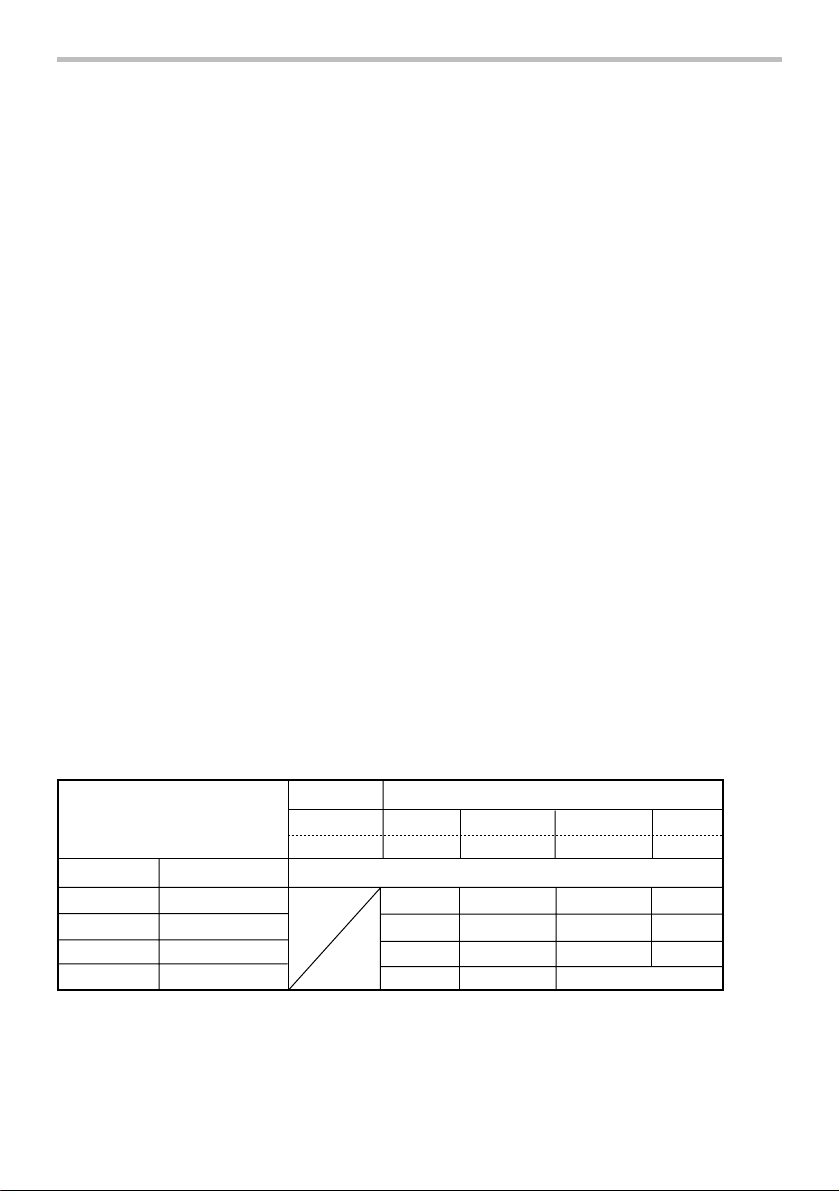
Ampere Rating
More Than Not More Than
06
6
10
12
000300
Table 1: Minimum gage for cord
Volts
Total length of cord in feet
120V 25 ft. 50 ft. 100 ft. 150 ft.
220V - 240V 50 ft. 100 ft. 200 ft. 300 ft.
AWG
18
10
12
16
18
16
14
16 16 14
1416
16
12
14
Not Recommended
12
12
3
Page 4

GEB007-7
ROTARY HAMMER SAFETY
WARNINGS
1. Wear ear protectors. Exposure to noise can
cause hearing loss.
2. Use auxiliary handle(s), if supplied with the
tool. Loss of control can cause personal injury.
3. Hold power tool by insulated gripping
surfaces, when performing an operation
where the cutting accessory may contact
hidden wiring or its own cord. Cutting
accessory contacting a "live" wire may make
exposed metal parts of the power tool "live" and
could give the operator an electric shock.
4. Wear a hard hat (safety helmet), safety
glasses and/or face shield. Ordinary eye or
sun glasses are NOT safety glasses. It is also
highly recommended that you wear a dust
mask and thickly padded gloves.
5. Be sure the bit is secured in place before
operation.
6. Under normal operation, the tool is designed
to produce vibration. The screws can come
loose easily, causing a breakdown or accident.
Check tightness of screws carefully before
operation.
7. In cold weather or when the tool has not been
used for a long time, let the tool warm up for a
while by operating it under no load. This will
loosen up the lubrication. Without proper
warm-up, hammering operation is difficult.
8. Always be sure you have a firm footing.
Be sure no one is below when using the tool
in high locations.
9. Hold the tool firmly with both hands.
10. Keep hands away from moving parts.
11. Do not leave the tool running. Operate the tool
only when hand-held.
12. Do not point the tool at any one in the area
when operating. The bit could fly out and
injure someone seriously.
13. Do not touch the bit or parts close to the bit
immediately after operation; they may be
extremely hot and could burn your skin.
14. Some material contains chemicals which may
be toxic. Take caution to prevent dust
inhalation and skin contact. Follow material
supplier safety data.
SAVE THESE INSTRUCTIONS.
WARNING:
DO NOT let comfort or familiarity with product
(gained from repeated use) replace strict adherence
to safety rules for the subject product. MISUSE or
failure to follow the safety rules stated in this
instruction manual may cause serious personal
injury.
USD202-2
Symbols
The followings show the symbols used for tool.
・ volts
・ amperes
・ hertz
・ alternating current
・ no load speed
・ Class II Construction
・ revolutions or reciprocation per minute
・ number of blow
4
Page 5
FUNCTIONAL DESCRIPTION
CAUTION:
• Always be sure that the tool is switched off and
unplugged before adjusting or checking function
on the tool.
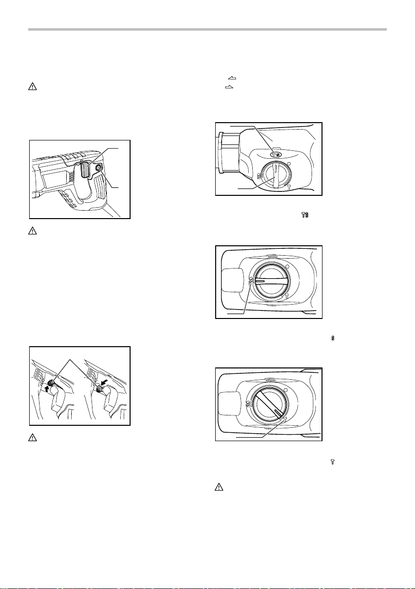
Switch action
1. Switch trigger
1
2. Lock button
This tool has a reversing switch to change the direction
of rotation. Move the reversing switch lever to
position (A side) for clockwise rotation or
the
the
position (B side) for counterclockwise rotation.
Selecting the action mode
Rotation with hammering
1
1. Rotation with
hammering
2. Action mode
changing knob
2
014361
CAUTION:
• Before plugging in the tool, always check to see
that the switch trigger actuates properly and
returns to the "OFF" position when released.
To start the tool, simply pull the switch trigger. Tool
speed is increased by increasing pressure on the switch
trigger. Release the switch trigger to stop. For
continuous operation, pull the switch trigger, push in the
lock button and then release the switch trigger. To stop
the tool from the locked position, pull the switch trigger
fully, then release it.
Reversing switch action
1
A
B
014362
CAUTION:
• Always check the direction of rotation before
operation.
• Use the reversing switch only after the tool comes
to a complete stop. Changing the direction of
rotation before the tool stops may damage the tool.
NOTE:
• When you operate the tool in counterclockwise
rotation, the switch trigger is pulled only halfway
and the tool runs at half speed. For
counterclockwise rotation, you cannot push in the
lock button.
1. Reversing switch
lever
2
010724
For drilling in concrete, masonry, etc., rotate the action
mode changing knob to the
symbol. Use a tungsten-
carbide tipped bit.
Rotation only
1. Rotation only
1
010726
For drilling in wood, metal or plastic materials, rotate the
action mode changing knob to the
symbol. Use a
twist drill bit or wood bit.
Hammering only
1. Hammering only
010725
1
For chipping, scaling or demolition operations, rotate the
action mode changing knob to the
bull point, cold chisel, scaling chisel, etc.
symbol. Use a
CAUTION:
•
Do not rotate the action mode changing knob when the
tool is running under load. The tool will be damaged.
• To avoid rapid wear on the mode change
mechanism, be sure that the action mode
changing knob is always positively located in one
of the three action mode positions.
5
Page 6
• Do not force the action mode change knob or do
not move it from
mode (or vise versa) at once. It may damage the
tool. When turning the knob from
mode to
at
symbol mode once. And rotate the chuck
clockwise (looking from the chuck side) half turn or
until it clicks. Then turn the knob to the desired
mode. If it is still difficult to turn the knob, rotate the
chuck again.
symbol mode to symbol
symbol
symbol mode (or vise versa), stop it
Torque limiter
The torque limiter will actuate when a certain torque
level is reached. The motor will disengage from the
output shaft. When this happens, the bit will stop turning.
CAUTION:
• As soon as the torque limiter actuates, switch off
the tool immediately. This will help prevent
premature wear of the tool.
• Bits such as hole saw, which tend to pinch or
catch easily in the hole, are not appropriate for this
tool. This is because they will cause the torque
limiter to actuate too frequently.
Hook
CAUTION:
• Never hook the tool at high location or on
potentially unstable surface.
1. Hook
1
ASSEMBLY
CAUTION:
• Always be sure that the tool is switched off and
unplugged before carrying out any work on the
tool.
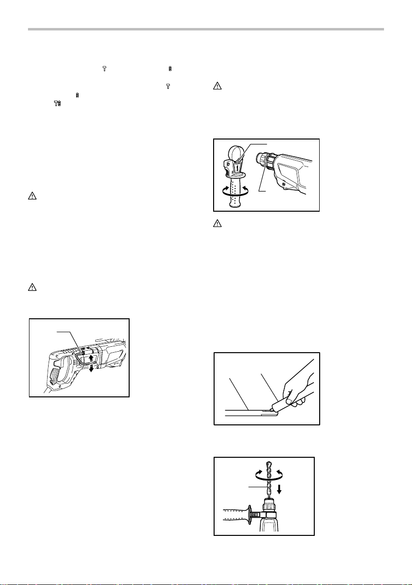
Side grip (auxiliary handle)
1
2
014500
CAUTION:
• Always use the side grip to ensure operating
safety.
Install the side grip so that the protrusions on the grip fit
in between the grooves on the tool barrel. Then tighten
the grip by turning clockwise at the desired position. It
may be swung 360° so as to be secured at any position.
Bit grease
Coat the bit shank head beforehand with a small
amount of bit grease (about 0.5 - 1 g).
This chuck lubrication assures smooth action and longer
service life.
Installing or removing the bit
1. Protrusions
2. Grooves
014368
The hook is convenient for hanging the tool temporarily.
To use the hook, simply lift up hook until it snaps into
the open position.
When not in use, always lower hook until it snaps into
the closed position.
1. Bit shank
1
003150
Clean the bit shank and apply bit grease before
installing the bit.
014430
6
2
1
2. Bit grease
1. Bit
Page 7
Insert the bit into the tool. Turn the bit and push it in until
it engages.
After installing, always make sure that the bit is securely
held in place by trying to pull it out.
To remove the bit, pull the chuck cover down all the way
and pull the bit out.
1. Bit
1
014501
2. Chuck cover
2
Bit angle
(when chipping, scaling or demolishing)
1. Action mode
changing knob
1
3
014431
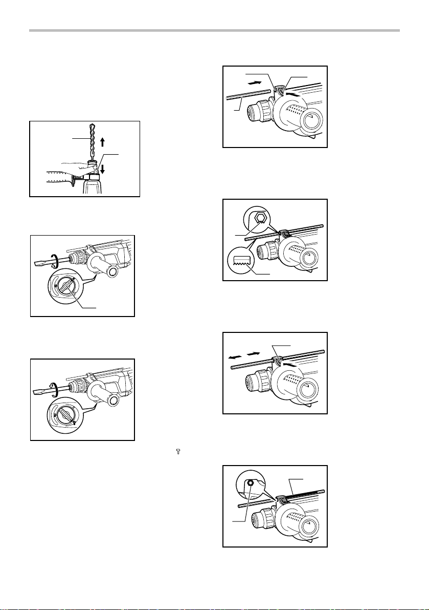
Press the lock button on the grip base in the direction of
arrow shown in the figure and with the lock button being
pressed insert the depth gauge into the hex. hole in the
grip base.
1
1. Grip base
2
2. Lock button
3. Depth gauge
1. Toothed side of
hex hole marking
on the grip base
2. Toothed side of
the depth gauge
1
014363
The bit can be secured at the desired angle. To change
the bit angle, rotate the action mode changing knob to
the O symbol. Turn the bit to the desired angle.
014364
Rotate the action mode changing knob to the symbol.
Then make sure that the bit is securely held in place by
turning it slightly.
Depth gauge
The depth gauge is convenient for drilling holes of
uniform depth.
014432
2
At this time, the depth gauge needs to be inserted so
that its toothed side is directed to the toothed side of
hex hole marking on the grip base as shown in the
figure.
1
014429
Adjust the depth gauge to the desired depth by moving
it back and forth while pressing the lock button. After the
adjustment, release the lock button to lock the depth
gauge.
1
014434
7
1. Lock button
1. Toothed side of
2
hex hole marking
on the grip base
2. Toothed side of
the depth gauge
Page 8
NOTE:
• Inserting the depth gauge with its toothed side not
directed to the toothed side of hex hole marking on
the grip base as shown in the figure does not allow
the depth gauge to be locked.
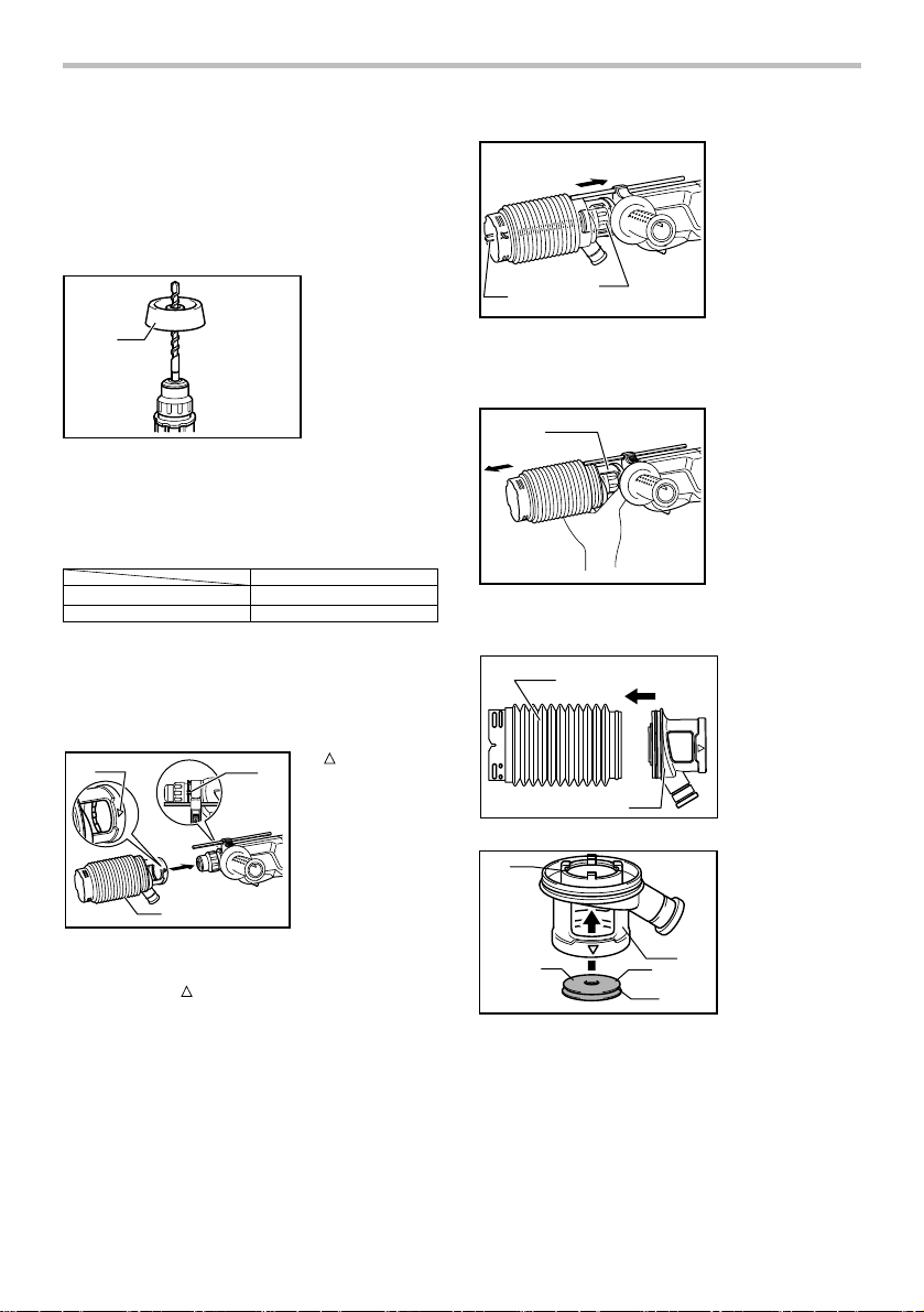
Dust cup (optional accessory)
1. Dust cup
1
010731
Use the dust cup to prevent dust from falling over the
tool and on yourself when performing overhead drilling
operations. Attach the dust cup to the bit as shown in
the figure. The size of bits which the dust cup can be
attached to is as follows.
Dust cup 5 6 mm (1/4") - 14.5 mm (9/16")
Dust cup 9 12 mm (15/32") - 16 mm (5/8")
006386
There is another type of dust cup which helps you
prevent dust from falling over the tool and on yourself
when performing overhead drilling operations.
Installing or removing the dust cup
(optional accessory)
1
014436
Before installing the dust cup, remove the bit from the
tool if installed on the tool. Install the dust cup on the
tool so that the
with the grooves in the tool.
3
symbol on the dust cup is aligned
Bit diameter
symbol
1.
2
2. Grooves
3. Dust cup
1. Bit
2. Chuck cover
1
014435
To remove the dust cup, pull the chuck cover in the
direction as shown in the figure and with the chuck
cover pulled take the bit out of the tool.
014441
And then grab the attachment at the foot of dust cup
and take it out.
011507
1
012895
2
1
1. Attachment at the
foot of dust cup
1
2
2
4
5
1. Bellows
2. Attachment
1. Inside periphery
2. Carved side
3. Attachment
4. Cap
5. Groove
3
8
Page 9
1
012896
NOTE:
• When installing or removing the dust cup, the cap
may come off the dust cup. At that time, proceed
as follows. Remove the bellows from the
attachment and fit the cap from the side shown in
the figure with its carved side facing upward so
that the groove in the cap fits in the inside
periphery of the attachment. Finally, mount the
bellows that has been removed.
014365
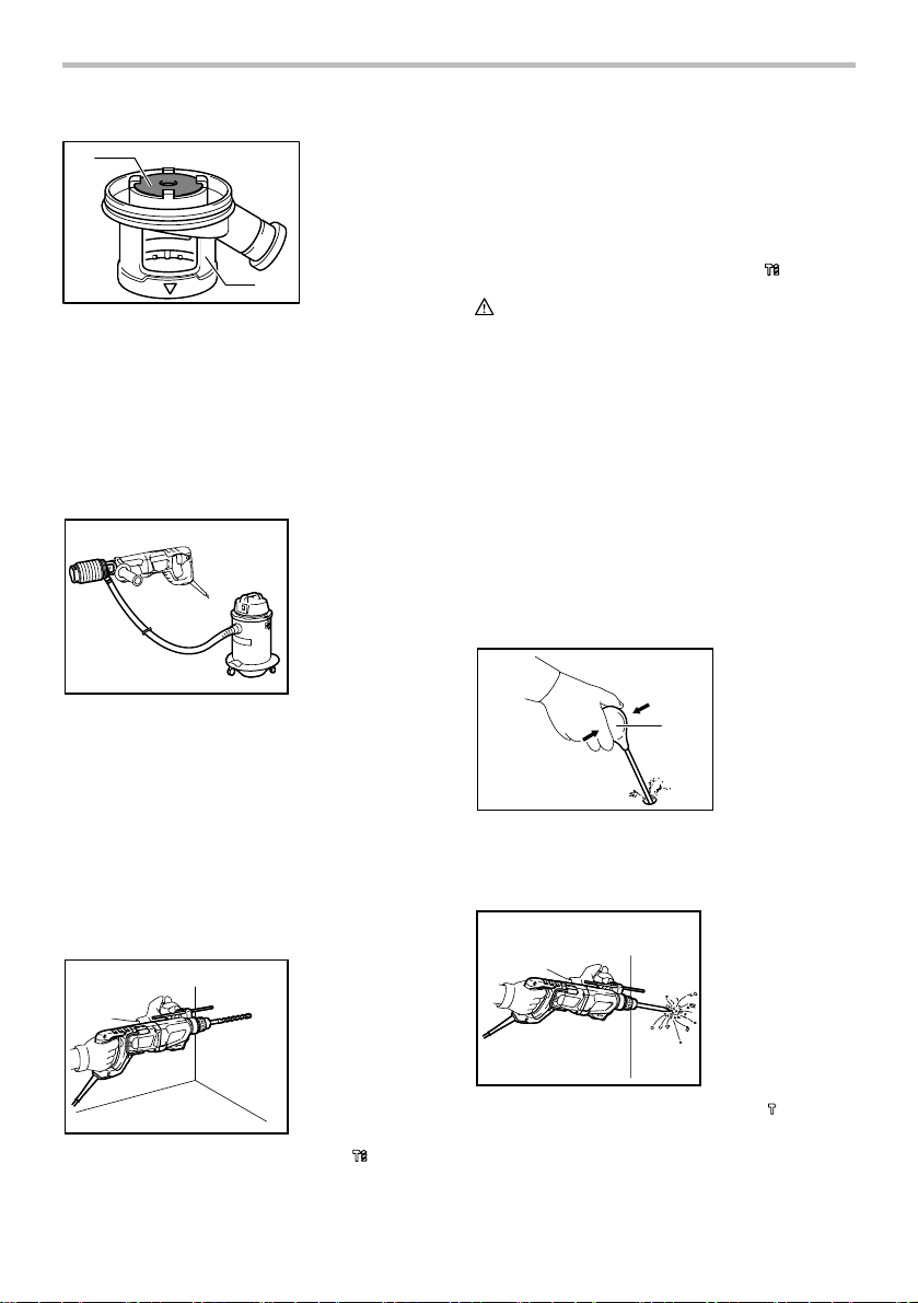
NOTE:
• If you connect a vacuum cleaner to your hammer,
cleaner operations can be performed. Dust cap
needs to be removed from the dust cup before the
connection.
1. Cap
2. Attachment
2
OPERATION
Always use the side grip (auxiliary handle) and firmly
hold the tool by both side grip and switch handle during
operations.
Hammer drilling operation
pressure gives best results. Keep the tool in position
and prevent it from slipping away from the hole.
Do not apply more pressure when the hole becomes
clogged with chips or particles. Instead, run the tool at
an idle, then remove the bit partially from the hole. By
repeating this several times, the hole will be cleaned out
and normal drilling may be resumed.
Set the action mode changing knob to the
CAUTION:
• There is a tremendous and sudden twisting force
exerted on the tool/bit at the time of hole breakthrough, when the hole becomes clogged with
chips and particles, or when striking reinforcing
rods embedded in the concrete. Always use the
side grip (auxiliary handle) and firmly hold the tool
by both side grip and switch handle during
operations. Failure to do so may result in the loss
of control of the tool and potentially severe injury.
NOTE:
Eccentricity in the bit rotation may occur while operating
the tool with no load. The tool automatically centers
itself during operation. This does not affect the drilling
precision.
symbol.
Blow-out bulb (optional accessory)
1. Blow-out bulb
1
002449
After drilling the hole, use the blow-out bulb to clean the
dust out of the hole.
Chipping/Scaling/Demolition
014366
Set the action mode changing knob to the symbol.
Position the bit at the desired location for the hole, then
pull the switch trigger. Do not force the tool. Light
014367
Set the action mode changing knob to the symbol.
Hold the tool firmly with both hands. Turn the tool on
and apply slight pressure on the tool so that the tool will
not bounce around, uncontrolled. Pressing very hard on
the tool will not increase the efficiency.
9
Page 10
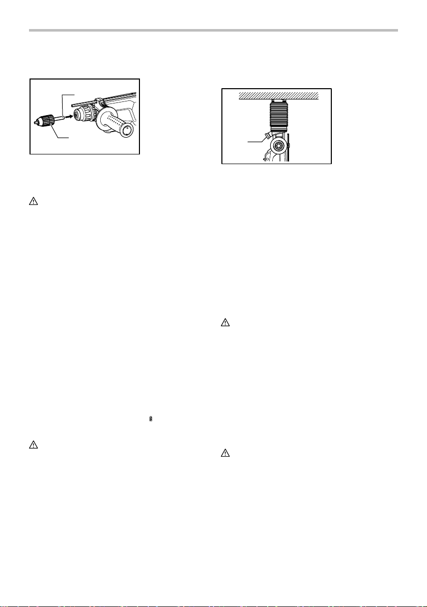
Drilling in wood or metal
1
1. Chuck adapter
2. Keyless drill
chuck
Operation when using the dust cup
(optional accessory)
1. Dust cap
2
014502
Use the optional drill chuck assembly. When installing it,
refer to "Installing or removing the bit" described on the
previous page.
CAUTION:
• Never use "rotation with hammering" when the
quick change drill chuck is installed on the tool.
The quick change drill chuck may be damaged.
Also, the drill chuck will come off when reversing
the tool.
• Pressing excessively on the tool will not speed up
the drilling. In fact, this excessive pressure will
only serve to damage the tip of your bit, decrease
the tool performance and shorten the service life
of the tool.
• There is a tremendous twisting force exerted on
the tool/bit at the time of hole breakthrough. Hold
the tool firmly and exert care when the bit begins
to break through the workpiece.
• A stuck bit can be removed simply by setting the
reversing switch to reverse rotation in order to
back out. However, the tool may back out abruptly
if you do not hold it firmly.
• Always secure small workpieces in a vise or
similar hold-down device.
Diamond core drilling
When performing diamond core drilling operations,
always set the change lever to the
"rotation only" action.
position to use
CAUTION:
• If performing diamond core drilling operations
using "rotation with hammering" action, the
diamond core bit may be damaged.
1
010736
Operate the tool with the dust cup against the ceiling
surface.
NOTE:
• The dust cup is intended only for drilling in the
ceramic workpiece such as concrete and mortar.
Do not use the tool with the dust cup when drilling
in metal or similar. Using the dust cup for drilling in
the metal may damage the dust cup due to the
heat produced by small metal dust or similar.
• Empty the dust cup before removing a drill bit.
• When using the dust cup, make sure that the dust
cap is mounted on it securely.
MAINTENANCE
CAUTION:
• Always be sure that the tool is switched off and
unplugged before attempting to perform inspection
or maintenance.
•
Never use gasoline, benzine, thinner, alcohol or the
like. Discoloration, deformation or cracks may result.
To maintain product SAFETY and RELIABILITY, repairs,
carbon brush inspection and replacement, any other
maintenance or adjustment should be performed by
Makita Authorized or Factory Service Centers, always
using Makita replacement parts.
OPTIONAL ACCESSORIES
CAUTION:
• These accessories or attachments are
recommended for use with your Makita tool
specified in this manual. The use of any other
accessories or attachments might present a risk of
injury to persons. Only use accessory or
attachment for its stated purpose.
If you need any assistance for more details regarding
these accessories, ask your local Makita Service Center.
• SDS-Plus Carbide-tipped bits
• Bull point
• Cold chisel
10
Page 11

• Scaling chisel
• Grooving chisel
• Drill chuck assembly
• Drill chuck S13
• Chuck adapter
• Chuck key S13
• Bit grease
• Side grip
• Depth gauge
• Blow-out bulb
• Dust cup
• Dust extractor attachment
• Safety goggles
• Plastic carrying case
• Keyless drill chuck
NOTE:
• Some items in the list may be included in the tool
package as standard accessories. They may differ
from country to country.
MAKITA LIMITED ONE YEAR WARRANTY
Warranty Policy
Every Makita tool is thoroughly inspected and tested
before leaving the factory. It is warranted to be free of
defects from workmanship and materials for the period
of ONE YEAR from the date of original purchase.
Should any trouble develop during this one year period,
return the COMPLETE tool, freight prepaid, to one of
Makita’s Factory or Authorized Service Centers. If
inspection shows the trouble is caused by defective
workmanship or material, Makita will repair (or at our
option, replace) without charge.
This Warranty does not apply where:
repairs have been made or attempted by others:
repairs are required because of normal wear and
tear:
the tool has been abused, misused or improperly
maintained:
alterations have been made to the tool.
IN NO EVENT SHALL MAKITA BE LIABLE FOR ANY
INDIRECT, INCIDENTAL OR CONSEQUENTIAL
DAMAGES FROM THE SALE OR USE OF THE
PRODUCT. THIS DISCLAIMER APPLIES BOTH
DURING AND AFTER THE TERM OF THIS
WARRANTY.
MAKITA DISCLAIMS LIABILITY FOR ANY IMPLIED
WARRANTIES, INCLUDING IMPLIED WARRANTIES
OF "MERCHANTABILITY" AND "FITNESS FOR A
SPECIFIC PURPOSE," AFTER THE ONE YEAR TERM
OF THIS WARRANTY.
This Warranty gives you specific legal rights, and you
may also have other rights which vary from state to
state. Some states do not allow the exclusion or
limitation of incidental or consequential damages, so
the above limitation or exclusion may not apply to you.
Some states do not allow limitation on how long an
implied warranty lasts, so the above limitation may not
apply to you.
EN0006-1
11
Page 12

FRANÇAIS (Mode d’emploi original)
SPÉCIFICATIONS
Modèle HR2621
Capacités
Vitesse à vide (RPM) 0 - 1 100 /min
Nombre de frappes par minute 0 - 4 500 /min
Longueur totale 422 mm (16-5/8")
Poids net 3,1 kg (6,8 lbs)
• Étant donné l'évolution constante de notre programme de recherche et de développement, les spécifications contenues dans ce
manuel sont sujettes à modification sans préavis.
• Les spécifications peuvent varier suivant les pays.
• Poids conforme à la procédure EPTA du 01/2003
Consignes de sécurité générales
pour outils électriques
MISE EN GARDE Veuillez lire toutes les mises
en garde de sécurité et toutes les instructions.
L'ignorance des mises en garde et des instructions
comporte un risque de choc électrique, d'incendie et/ou
de blessure grave.
Conservez toutes les mises en
garde et instructions pour
référence future.
Le terme ≪ outil électrique ≫ qui figure dans les
avertissements fait référence à un outil électrique
branché sur une prise de courant (par un cordon
d'alimentation) ou alimenté par batterie (sans fil).
Sécurité de la zone de travail
1. Maintenez la zone de travail propre et bien
éclairée. Les zones de travail encombrées ou
sombres ouvrent grande la porte aux accidents.
2. N'utilisez pas les outils électriques dans les
atmosphères explosives, par exemple en
présence de liquides, gaz ou poussières
inflammables. Les outils électriques produisent
des étincelles au contact desquelles la poussière
ou les vapeurs peuvent s'enflammer.
3. Assurez-vous qu'aucun enfant ou curieux ne
s'approche pendant que vous utilisez un outil
électrique. Vous risquez de perdre la maîtrise de
l'outil si votre attention est détournée.
Sécurité en matière d'électricité
4. Les fiches d'outil électrique sont conçues
pour s'adapter parfaitement aux prises de
courant. Ne modifiez jamais la fiche de
Béton 26 mm (1")
Trépan 68 mm (2-11/16")
Acier 13 mm (1/2")
Bois 32 mm (1-1/4")
GEA008-2
quelque façon que ce soit. N'utilisez aucun
adaptateur de fiche sur les outils électriques
avec mise à la terre. En ne modifiant pas les
fiches et en les insérant dans des prises de
courant pour lesquelles elles ont été conçues
vous réduirez les risques de choc électrique.
5. Évitez tout contact corporel avec les surfaces
mises à la terre, telles que les tuyaux,
radiateurs, cuisinières et réfrigérateurs. Le
risque de choc électrique est plus élevé si votre
corps se trouve mis à la terre.
6. N'exposez pas les outils électriques à la pluie
ou à l'eau. La présence d'eau dans un outil
électrique augmente le risque de choc électrique.
7. Ne maltraitez pas le cordon. N'utilisez jamais
le cordon pour transporter, tirer ou
débrancher l'outil électrique. Maintenez le
cordon à l'écart des sources de chaleur, de
l'huile, des objets à bords tranchants et des
pièces en mouvement. Le risque de choc
électrique est plus élevé lorsque les cordons sont
endommagés ou enchevêtrés.
8. Lorsque vous utilisez un outil électrique à
l'extérieur, utilisez un cordon prolongateur
prévu à cette fin. Les risques de choc électrique
sont moindres lorsqu'un cordon conçu pour
l'extérieur est utilisé.
9. Si vous devez utiliser un outil électrique dans
un endroit humide, utilisez une source
d'alimentation protégée par un disjoncteur de
fuite à la terre. L'utilisation d'un disjoncteur de
fuite à la terre réduit le risque de choc électrique.
Sécurité personnelle
10. Restez alerte, attentif à vos mouvements et
faites preuve de bon sens lorsque vous
utilisez un outil électrique. Évitez d'utiliser un
12
Page 13

outil électrique si vous êtes fatigué ou si vous
avez pris une drogue, de l'alcool ou un
médicament. Un moment d'inattention pendant
l'utilisation d'un outil électrique peut entraîner une
grave blessure.
11. Portez des dispositifs de protection
personnelle. Portez toujours un protecteur
pour la vue. Les risques de blessure seront
moins élevés si vous utilisez des dispositifs de
protection tels qu'un masque antipoussières, des
chaussures à semelle antidérapante, une coiffure
résistante ou une protection d'oreilles.
12. Évitez les démarrages accidentels. Assurez-
vous que l'interrupteur est en position d'arrêt
avant de brancher l'outil et/ou d'insérer la
batterie, ainsi qu'avant de saisir ou de
transporter l'outil. Vous ouvrez la porte aux
accidents si vous transportez les outils
électriques avec le doigt sur l'interrupteur ou
laissez l'interrupteur en position de marche avant
de mettre l'outil sous tension.
13. Retirez toute clé de réglage ou de serrage
avant de mettre l'outil sous tension. Tout e cl é
laissée en place sur une pièce rotative de l'outil
électrique peut entraîner une blessure.
14. Maintenez une bonne position. Assurez-vous
d'une bonne prise au sol et d'une bonne
position d'équilibre en tout temps. Cela vous
permettra d'avoir une meilleure maîtrise de l'outil
dans les situations imprévues.
15. Portez des vêtements adéquats. Ne portez ni
vêtements amples ni bijoux. Vous devez
maintenir cheveux, vêtements et gants à
l'écart des pièces en mouvement. Les pièces
en mouvement peuvent happer les vêtements
amples, les bijoux et les cheveux longs.
16. Si des accessoires sont fournis pour
raccorder un appareil d'aspiration et de
collecte de la poussière, assurez-vous qu'ils
sont correctement raccordés et qu'ils sont
utilisés de manière adéquate. L'utilisation d'un
appareil d'aspiration permet de réduire les
risques liés à la présence de poussière dans l'air.
Utilisation et entretien des outils électriques
17. Ne forcez pas l'outil électrique. Utilisez l'outil
électrique adéquat suivant le type de travail à
effectuer. Si vous utilisez l'outil électrique
adéquat et respectez le régime pour lequel il a
été conçu, il effectuera un travail de meilleure
qualité et de façon plus sécuritaire.
18. N'utilisez pas l'outil électrique s'il n'est pas
possible de mettre sa gâchette en position de
marche et d'arrêt. Un outil électrique dont
l'interrupteur est défectueux représente un
danger et doit être réparé.
19. Débranchez la fiche de la source
d'alimentation et/ou retirez le bloc-piles de
l'outil électrique avant d'effectuer tout réglage,
de changer un accessoire ou de ranger l'outil
électrique. De telles mesures préventives
réduisent les risques de démarrage accidentel de
l'outil électrique.
20. Après l'utilisation d'un outil électrique,
rangez-le hors de portée des enfants et ne
laissez aucune personne l'utiliser si elle n'est
pas familiarisée avec l'outil électrique ou les
présentes instructions d'utilisation. Les outils
électriques représentent un danger entre les
mains de personnes qui n'en connaissent pas le
mode d'utilisation.
21. Veillez à l’entretien des outils électriques.
Assurez-vous que les pièces mobiles ne sont
pas désalignées ou coincées, qu’aucune
pièce n’est cassée et que l’outil électrique n’a
subi aucun dommage affectant son bon
fonctionnement. Le cas échéant, faites
réparer l'outil électrique avant de l'utiliser. De
nombreux accidents sont causés par des outils
électriques mal entretenus.
22. Maintenez les outils tranchants bien aiguisés
et propres. Un outil tranchant dont l'entretien est
effectué correctement et dont les bords sont bien
aiguisés risquera moins de se coincer et sera
plus facile à maîtriser.
23. Utilisez l'outil électrique, ses accessoires, ses
embouts, etc., en respectant les présentes
instructions, en tenant compte des conditions
de travail et du type de travail à effectuer.
L'utilisation d'un outil électrique à des fins autres
que celles prévues peut entraîner une situation
dangereuse.
Réparation
24. Faites réparer votre outil électrique par un
réparateur qualifié qui utilise des pièces de
rechange identiques aux pièces d'origine. Le
maintien de la sûreté de l'outil électrique sera
ainsi assuré.
25. Suivez les instructions de lubrification et de
changement des accessoires.
26. Maintenez les poignées de l'outil sèches,
propres et exemptes d'huile ou de graisse.
UTILISEZ UN CORDON PROLONGATEUR
APPROPRIÉ. Assurez-vous que votre cordon
prolongateur est en bonne condition. Lorsque vous
utilisez un cordon prolongateur, assurez-vous qu'il est
assez robuste pour transporter le courant exigé par le
produit. Un cordon qui est trop petit entraînera une
baisse dans la tension composée, ce qui causera une
perte d'énergie et un surchauffage. Le tableau 1 indique
la dimension de cordon à utiliser, en fonction de la
13
Page 14

longueur du cordon et de l'intensité nominale figurant
sur la plaque signalétique. En cas de doute, utilisez un
cordon plus robuste. Plus le numéro de calibre est bas,
plus le cordon est robuste.
Tableau 1. Gabarit minimum du cordon
Vol ts
Intensité nominale
120V 25 pi 50 pi 100 pi 150 pi
220V - 240V 50 pi 100 pi 200 pi 300 pi
Plus de Pas plus de
06
6
10
12
000300
10
12
16
GEB007-7
CONSIGNES DE SÉCURITÉ
POUR MARTEAU ROTATIF
1. Portez des protections d'oreilles. L'exposition
au bruit peut entraîner des lésions de l'ouïe.
2. Utilisez la ou les poignées auxiliaires si elles
sont fournies avec l'outil. Toute perte de
maîtrise comporte un risque de blessure.
3. Tenez l’outil électrique par ses surfaces de
prise isolées pendant toute opération où
l’accessoire de coupe pourrait venir en
contact avec un câblage dissimulé ou avec
son propre cordon. En cas de contact de
l’accessoire de coupe avec un conducteur sous
tension, les pièces métalliques à découvert de
l’outil électrique risqueraient de transmettre une
décharge à l’utilisateur.
4. Portez un casque rigide (casque de sécurité)
ainsi que des lunettes de sécurité et/ou un
écran facial. Les lunettes ordinaires et les
lunettes de soleil ne constituent PAS des
lunettes de sécurité. Le port d'un masque à
poussière et de gants épais est également
fortement recommandé.
5. Assurez-vous que le foret est bien serré avant
d'utiliser l'outil.
6. Même dans des conditions d'utilisation
ordinaires, l'outil produit des vibrations. Les
vis peuvent ainsi se relâcher facilement et
risquent d'entraîner une rupture de pièce ou
de causer un accident. Avant l'utilisation,
vérifiez avec précaution que les vis sont bien
serrées.
Longueur totale du cordon en pieds
Calibre américain des fils
18
18
16
14
16 16 14
1416
16
12
7. Par temps froid ou lorsque l'outil est resté
inutilisé pendant une longue période, faites-le
réchauffer pendant quelques minutes en le
faisant fonctionner à vide. Cela réchauffera le
lubrifiant. Sans un réchauffement adéquat, le
martelage s'effectue difficilement.
8. Adoptez toujours une position de travail vous
assurant d'un bon équilibre.
Assurez-vous qu'il n'y a personne plus bas
lorsque vous utilisez l'outil en position élevée.
9. Tenez l'outil fermement à deux mains.
10. Gardez vos mains éloignées des pièces
mobiles.
11. N'abandonnez pas l'outil alors qu'il tourne. Ne
faites fonctionner l'outil qu'une fois que vous
l'avez bien en main.
12. Pendant l'utilisation de l'outil, ne le pointez
vers personne dans la zone de travail. Vous
risqueriez de blesser gravement quelqu'un en
cas d'éjection du foret.
13. Ne touchez pas le foret ou les parties situées
près du foret immédiatement après
l'utilisation ; ils peuvent être extrêmement
chauds et brûler votre peau.
14. Certains matériaux contiennent des produits
chimiques qui peuvent être toxiques. Prenez
les précautions nécessaires pour éviter
l'inhalation de ces poussières ou leur contact
avec la peau. Conformez-vous aux consignes
de sécurité du fournisseur du matériau.
14
Non recommandé
12
12
CONSERVEZ CE MODE
D'EMPLOI.
14
Page 15

AVERTISSEMENT:
NE VOUS LAISSEZ PAS tromper (au fil d'une
utilisation répétée) par un sentiment d'aisance ou
de familiarité avec le produit en négligeant les
consignes de sécurité qui accompagnent le produit.
L'utilisation non sécuritaire ou incorrecte de cet
outil comporte un risque de blessure grave.
USD202-2
Symboles
Les symboles utilisés pour l'outil sont indiqués cidessous.
・ volts
・ ampères
・ hertz
・ courant alternatif
・ vitesse à vide
・ construction, catégorie II
・ tours ou alternances par minute
・ nombre de frappes
DESCRIPTION DU
FONCTIONNEMENT
ATT EN TI ON :
• Assurez-vous toujours que l'outil est hors tension
et débranché avant de l'ajuster ou de vérifier son
fonctionnement.
Interrupteur
1. Gâchette
1
2. Bouton de
verrouillage
2
014361
ATT EN TI ON :
• Avant de brancher l'outil, assurez-vous toujours
que la gâchette fonctionne correctement et revient
en position d'arrêt une fois relâchée.
Pour faire démarrer l'outil, appuyez simplement sur la
gâchette. La vitesse de l'outil augmente à mesure que vous
augmentez la pression sur la gâchette. Pour arrêter l'outil,
relâchez la gâchette. Pour un fonctionnement en continu,
appuyez sur la gâchette, enfoncez le bouton de verrouillage et
relâchez la gâchette. Pour arrêter l'outil à partir de la position
verrouillée, pressez la gâchette à fond, puis relâchez-la.
Inverseur
1
1. Levier inverseur
A
B
014362
ATT EN TI ON :
• Vérifiez toujours le sens de rotation avant de
mettre l'outil en marche.
• N'actionnez l'inverseur qu'une fois que l'outil est
complètement arrêté. Si vous changez le sens de
rotation avant l'arrêt de l'outil, vous risquez de
l'endommager.
NOTE:
•
Lorsque vous faites fonctionner l'outil avec une rotation
dans le sens inverse des aiguilles d'une montre, la
15
Page 16

gâchette n'est enfoncée qu'à mi-chemin et l'outil ne
tourne qu'à mi-vitesse. De plus, avec la rotation dans le
sens inverse des aiguilles d'une montre, il n'est pas
possible d'enfoncer le bouton de verrouillage.
Cet outil est équipé d'un inverseur pour changer le sens de
rotation. Déplacez le levier de l'inverseur sur la position
(côté A) pour une rotation dans le sens des aiguilles d'une
montre, ou sur la position
(côté B) pour une rotation
dans le sens contraire des aiguilles d'une montre.
Sélection du mode de fonctionnement
Rotation avec martelage
1
2
010724
Pour percer un trou dans le béton, la maçonnerie, etc. faites
pivoter le bouton de changement de mode sur le symbole
. Utilisez un foret à pointe en carbure de tungstène.
Rotation seulement
1
010726
Pour percer un trou dans le bois, le métal ou les
matériaux plastiques, faites pivoter le bouton de
changement de mode sur le symbole
foret hélicoïdal ou à bois.
Martelage seulement
1. Rotation avec
martelage
2. Bouton de
changement de
mode
1. Rotation
seulement
. Utilisez un
1. Martelage
seulement
ATT EN TI ON :
• Ne tournez pas le bouton de changement de
mode lorsque l'outil est en fonctionnement : vous
risquez de l'endommager.
• Pour éviter toute usure prématurée du mécanisme
de changement de mode, veillez à ce que le
bouton de changement de mode soit toujours bien
réglé sur l'un des trois modes.
•
Ne forcez pas le bouton de changement de mode
et évitez de le faire passer directement du symbole
de mode
au symbole de mode (ou vice
versa). Cela risque d’endommager l’outil. Lorsque
vous tournez le bouton pour le faire passer du
symbole de mode
au symbole de mode (ou
vice versa), faites une pause au symbole de mode
. Tournez le mandrin d’un demi-tour dans le sens
des aiguilles d’une montre (vue du mandrin) ou
jusqu’au déclic. Tournez ensuite le bouton au mode
désiré. S’il est encore difficile de tourner le bouton,
faites encore tourner le mandrin.
Limiteur de couple
Le limiteur de couple se déclenche lorsqu'un certain
niveau de couple est atteint. Le moteur se désaccouple
du porte-outil. Dans ce cas, le foret cesse de tourner.
ATT EN TI ON :
• Coupez le contact dès que le limiteur de couple se
déclenche. Ceci permettra d'éviter toute usure
prématurée de l'outil.
• Les forets tels que les scies cloches qui ont
tendance à se bloquer dans le trou ne sont pas
appropriés pour cet outil. Elles déclenchent trop
fréquemment le limiteur de couple.
Crochet
ATT EN TI ON :
• Ne suspendez jamais l'outil dans un endroit très
élevé ou sur une surface qui risque d'être instable.
1. Crochet
1
010725
1
Pour un burinage, un écaillage, ou des travaux de
démolition, faites pivoter le bouton de changement de
mode sur le symbole
ciseau à froid, un ciseau à écailler, etc.
. Utilisez une pointe à béton, un
014368
Le crochet a été conçu afin de pouvoir suspendre l'outil
de façon temporaire. Pour utiliser le crochet, soulevezle jusqu'à ce qu'il soit en position ouverte.
Lorsqu'il n'est pas utilisé, abaissez toujours le crochet
jusqu'à ce qu'il soit en position fermée.
16
Page 17

ASSEMBLAGE
ATT EN TI ON :
•
Avant d'effectuer toute intervention sur l'outil, assurezvous toujours qu'il est hors tension et débranché.
Poignée latérale (poignée auxiliaire)
1
1. Saillies
2. Rainures
Insérez le foret dans l'outil. Tournez le foret puis
enfoncez-le jusqu'à ce qu'il soit engagé.
Après l'installation, vérifiez toujours que le foret est
solidement fixé en essayant de le sortir.
Pour retirer le foret, tirez le couvercle du mandrin à fond
vers le bas puis dégagez le foret.
1. Embout
2
2. Couvercle du
mandrin
1
2
014500
ATT EN TI ON :
• Utilisez toujours la poignée latérale pour assurer
votre sécurité.
Installez la poignée latérale de sorte que les parties saillantes
de la poignée pénètrent entre les rainures du barillet de l’outil.
Serrez ensuite la poignée sur la position désirée en tournant
dans le sens des aiguilles d’une montre. Elle doit être tournée
à 360° afin de rester fixe dans toutes les positions.
Graisse rose
Avant de procéder, enduisez la queue du foret d'une
légère couche de graisse (environ 0,5 - 1 g).
Cette lubrification du porte-outil assurera un fonctionnement
en douceur et une longue durée de service.
Installation et retrait du embout
1. Queue du foret
1
003150
Nettoyez la queue du foret et enduisez-la de graisse à
foret avant d'installer le foret.
2
1
2. Graisse à foret
1. Embout
014501
Orientation du foret (lors d'un burinage, d'un
écaillage, ou de travaux de démolition)
1. Bouton de
changement de
mode
1
014363
Le foret peut être fixé à l’angle désiré. Pour changer
l’orientation du foret, faites pivoter le bouton de
changement de mode sur le symbole O. Orientez le
foret à l’angle désiré.
014364
Faites pivoter le bouton de changement de mode sur le
symbole
le tournant légèrement.
. Vérifiez que le foret est solidement fixé en
Jauge de profondeur
La jauge de profondeur est pratique pour percer des
trous d’une même profondeur.
014430
17
Page 18

1
3
014431
Appuyez sur le bouton de verrouillage à la base de la
poignée dans le sens de la flèche indiqué sur le schéma, et,
tout en le maintenant enfoncé, insérez la jauge de
profondeur dans l’orifice hexagonal à la base de la poignée.
1
2
014432
À ce moment-là, la jauge de profondeur doit être
insérée de telle sorte que son côté cranté soit dirigé
vers le marquage du côté cranté de l'orifice sur la base
de la poignée comme indiqué sur le schéma.
1
014429
Réglez la jauge de profondeur à la profondeur
souhaitée en la tirant ou en la poussant tout en
appuyant sur le bouton de verrouillage. Une fois le
réglage effectué, relâchez le bouton de verrouillage
pour verrouiller la jauge de profondeur.
1
1. Base de la
2
poignée
2. Bouton de
verrouillage
3. Jauge de
profondeur
1. Marquage du côté
cranté de l’orifice
hexagonal sur la
base de la
poignée
2. Côté cranté de la
jauge de
profondeur
1. Bouton de
verrouillage
1. Marquage du côté
2
cranté de l’orifice
hexagonal sur la
base de la
poignée
2. Côté cranté de la
jauge de
profondeur
NOTE:
• Si la jauge de profondeur est insérée sans que
son côté cranté ne soit dirigé vers le marquage du
côté cranté de l’orifice hexagonal à la base de la
poignée comme indiqué sur le schéma, alors elle
ne pourra pas être verrouillée.
Collecteur de poussières
(accessoire en option)
1. Collecteur de
poussières
1
010731
Pour éviter que la poussière qui s'échappe du trou ne
tombe sur vous lors d'un travail au-dessus de la tête,
utilisez le collecteur de poussières. Engagez le
collecteur sur le foret comme indiqué sur la figure. La
taille de forets qu'il est possible de fixer au collecteur est
comme suit.
Collecteur de poussières 5 6 mm (1/4") - 14,5 mm (9/16")
Collecteur de poussières 9 12 mm (15/32") - 16 mm (5/8")
006386
Il existe un autre type de collecteur de poussières qui
permet d’empêcher la poussière de tomber sur vous et
sur l’outil lorsque vous percez un trou au-dessus de
votre tête.
Installation ou retrait du collecteur de poussières
(accessoire en option)
1
014436
Avant d’installer le collecteur de poussières, retirez le
foret de l’outil s'il y en a un. Installez le collecteur de
poussières sur l'outil de manière à ce que le symbole
sur le collecteur de poussières soit aligné avec les
rainures de l'outil.
3
Diamètre du foret
symbole
1.
2
2. Rainures
3. Collecteur de
poussières
014434
18
Page 19

1. Embout
2. Couvercle du
mandrin
1
1. Bouchon
2. Dispositif de
fixation
1
014435
Pour retirer le collecteur de poussières, tirez la
protection du mandrin dans la direction indiquée sur le
schéma, et, tout en la maintenant tirée, retirez le foret
de l’outil.
014441
Puis saisissez le dispositif de fixation à la base du
collecteur de poussières et retirez-le.
011507
1
012895
2
1
1. Dispositif de
fixation à la base
du collecteur de
poussières
1
2
2
4
5
1. Soufflet
2. Dispositif de
fixation
1. Bord intérieur
2. Face ciselée
3. Dispositif de
fixation
4. Bouchon
5. Rainure
3
2
012896
NOTE:
•
Lorsque vous installez ou retirez le collecteur de
poussières, le couvercle peut s’en détacher. À ce
moment-là, procédez comme suit. Retirez le soufflet
du dispositif de fixation et placez le couvercle,
comme indiqué sur le schéma, face ciselée vers le
haut de manière à ce que ses rainures s'emboîtent
dans le bord intérieur du dispositif de fixation. Pour
finir, remontez le soufflet précédemment retiré.
014365
NOTE:
• Si vous raccordez un aspirateur au marteau, vous
effectuerez votre travail de façon plus propre. Le
couvercle doit être retiré du collecteur de
poussières avant le raccordement.
UTILISATION
Utilisez toujours la poignée la latérale (poignée auxiliaire) et
saisissez fermement l'outil par la poignée latérale et la
poignée de l'interrupteur pendant l'utilisation.
Perçage avec martelage
014366
Réglez le bouton de changement de mode sur le symbole .
Posez la pointe du foret à l'emplacement du trou à
percer et pressez sur la gâchette. Ne forcez pas sur
19
Page 20

l'outil. Une pression légère vous donnera les meilleurs
résultats. Maintenez bien l'outil en position et veillez
qu'il ne dérape pas hors du trou.
N'augmentez pas la pression sur l'outil lorsque le trou
est bouché par des copeaux ou des particules. Au
contraire, laissez le moteur tourner au ralenti, puis
retirez en partie le foret du trou. Si vous répétez cette
opération plusieurs fois de suite, le trou se débouchera,
et vous pourrez reprendre le perçage normalement.
Réglez le bouton de changement de mode sur le
symbole
.
ATT EN TI ON :
•
Une force énorme s'exerce sur le foret et l'outil lorsque
le foret émerge sur la face opposée, lorsque le trou
est encombré de copeaux ou de particules, ou lors de
la frappe sur des barres d'armature encastrées dans
le béton. Utilisez toujours la poignée latérale (poignée
auxiliaire) et tenez fermement l'outil par la poignée
latérale et par la poignée revolver lors des travaux.
Sinon, vous risquez de perdre le contrôle de l'outil et
de subir une blessure grave.
NOTE:
Lorsque l'outil fonctionne à vide, il se peut que le foret
tourne de manière excentrique. L'outil se centrera luimême lors de l'utilisation avec charge. La précision du
perçage n'est donc pas affectée.
Poire soufflante (accessoire en option)
1. Poire soufflante
1
002449
Une fois le trou percé, utilisez la poire soufflante pour
retirer la poussière du trou.
Burinage / Ecaillage / Démolition
014367
Réglez le bouton de changement de mode sur le
symbole
.
Tenez votre outil fermement à deux mains. Mettez le
contact et appliquez une légère pression sur l'outil de
façon qu'il ne risque pas de sauter d'un côté ou de
l'autre. Appliquer une pression excessive n'augmentera
pas l'efficacité de l'opération.
Perçage du bois ou du métal
1. Adaptateur de
1
mandrin
2. Mandrin
autoserrant
2
014502
Utilisez l'ensemble mandrin en option. Lorsque vous
l'installez, référez-vous à la section ''Installation ou
retrait du foret'', à la page précédente.
ATT EN TI ON :
• N'utilisez jamais la ≪ rotation avec martelage ≫
lorsque le mandrin à adaptateur rapide est posé
sur l'outil. Vous risqueriez d'endommager le
mandrin à adaptateur rapide.
De plus, le mandrin se détacherait lors de
l'inversion de l'outil.
• Une pression excessive sur l'outil n'accélère pas
le perçage. Au contraire, elle risque
d'endommager la pointe du foret, de réduire le
rendement de l'outil et donc sa durée de service.
• Une force énorme s'exerce sur le foret et l'outil
lorsque le foret émerge sur la face opposée.
Tenez l'outil fermement et faites bien attention
lorsque le foret commence à sortir de la face
opposée de la pièce.
• Un foret coincé peut se retirer en plaçant
l'inverseur sur la direction opposée. Il faut alors
faire très attention car l'outil risque de reculer
brusquement si vous ne le tenez pas fermement.
• Lorsque vous travaillez sur de petites pièces,
fixez-les toujours dans un étau ou à l’aide d’un
outil de retenue similaire.
Perforation au diamant
Lors d'opérations de perforation au diamant, toujours
positionner le levier de changement sur
"rotation seulement".
pour l'action
ATT EN TI ON :
• En cas d'opérations de forage au diamant avec
l'action "rotation avec martelage", le foret de
diamant peut être endommagé.
20
Page 21

Fonctionnement lors de l’utilisation du
collecteur de poussières
(accessoire en option)
1. Cachepoussière
1
010736
Utilisez l'outil avec le collecteur de poussières pour
percer les plafonds.
NOTE:
• Le collecteur de poussières est conçu uniquement
pour percer dans les matériaux céramiques tels
que le béton et le mortier. N’utilisez pas l’outil avec
le collecteur de poussières pour le perçage du
métal ou d’un matériau similaire. Utiliser le
collecteur de poussières pour le perçage du métal
peut l'endommager car les poussières de métal ou
d’un matériau similaire produisent de la chaleur.
• Videz le collecteur de poussières avant de retirer
un foret.
•
Lorsque vous utilisez le collecteur de poussières,
assurez-vous que le couvercle est bien fixé dessus.
ENTRETIEN
ATT EN TI ON :
• Assurez-vous toujours que l'outil est hors tension
et débranché avant d'y effectuer tout travail
d'inspection ou d'entretien.
• N'utilisez jamais d'essence, de benzine, de solvant,
d'alcool ou d'autres produits similaires. Une
décoloration, une déformation, ou la formation de
fissures peuvent en découler.
Pour maintenir la SÉCURITÉ et la FIABILITÉ du produit,
les réparations, l'inspection et le remplacement des
charbons, et tout autre travail d'entretien ou de réglage
doivent être effectués dans une usine ou un centre de
service après-vente Makita agréé, exclusivement avec
des pièces de rechange Makita.
ACCESSOIRES EN OPTION
ATT EN TI ON :
• Ces accessoires ou pièces complémentaires sont
recommandés pour l'utilisation avec l'outil Makita
spécifié dans ce mode d'emploi. L'utilisation de
tout autre accessoire ou pièce complémentaire
peut comporter un risque de blessure. N'utilisez
les accessoires ou pièces qu'aux fins auxquelles
ils ont été conçus.
Si vous désirez obtenir plus de détails concernant ces
accessoires, veuillez contacter le centre de service
après-vente Makita le plus près.
• Foret à pointe en carbure de tungstène SDS-Plus
• Pointe à béton
• Ciseau à froid
• Ciseau à écailler
• Ciseau à rainure
• Ensemble mandrin
• Mandrin S13
• Adaptateur de mandrin
• Clé à mandrin S13
• Graisse rose
• Poignée latérale
• Jauge de profondeur
• Poire soufflante
• Collecteur de poussières
• Aspirateur
• Lunettes de sécurité
• Mallette de transport en plastique
• Mandrin auto-serrant
NOTE:
• Certains éléments de la liste peuvent être inclus
avec l'outil comme accessoires standard. Ils
peuvent varier suivant les pays.
21
Page 22

GARANTIE LIMITÉE D’UN AN MAKITA
A
À
A
Politique de garantie
Chaque outil Makita est inspecté rigoureusement et
testé avant sa sortie d’usine. Nous garantissons qu’il
sera exempt de défaut de fabrication et de vice de
matériau pour une période d’UN AN à partir de la date
de son achat initial. Si un problème quelconque devait
survenir au cours de cette période d’un an, veuillez
retourner l’outil COMPLET, port payé, à une usine ou à
un centre de service après-vente Makita. Makita
réparera l’outil gratuitement (ou le remplacera, à sa
discrétion) si un défaut de fabrication ou un vice de
matériau est découvert lors de l’inspection.
Cette garantie ne s’applique pas dans les cas où:
des réparations ont été effectuées ou tentées par
un tiers:
des réparations s’imposent suite à une usure
normale:
l’outil a été malmené, mal utilisé ou mal entretenu:
l’outil a subi des modifications.
MAKITA DÉCLINE TOUTE RESPONSABILITÉ POUR
TOUT DOMMAGE ACCESSOIRE OU INDIRECT LIÉ À
LA VENTE OU À L’UTILISATION DU PRODUIT. CET
VIS DE NON-RESPONSABILITÉ S’APPLIQUE À LA
FOIS PENDANT ET APRÈS LA PÉRIODE COUVERTE
PAR CETTE GARANTIE.
MAKITA DÉCLINE TOUTE RESPONSABILITÉ QUANT
TOUTE GARANTIE TACITE, INCLUANT LES
GARANTIES TACITES DE “QUALITÉ MARCHANDE”
ET “ADÉQUATION À UN USAGE PARTICULIER”
PRÈS LA PÉRIODE D’UN AN COUVERTE PAR
CETTE GARANTIE.
Cette garantie vous donne des droits spécifiques
reconnus par la loi, et possiblement d’autres droits, qui
varient d’un État à l’autre. Certains États ne permettant
pas l’exclusion ou la limitation des dommages
accessoires ou indirects, il se peut que la limitation ou
exclusion ci-dessus ne s’applique pas à vous. Certains
États ne permettant pas la limitation de la durée
d’application d’une garantie tacite, il se peut que la
limitation ci-dessus ne s’applique pas à vous.
EN0006-1
22
Page 23

ESPAÑOL (Instrucciones originales)
ESPECIFICACIONES
Especificaciones eléctricas en México 120 V 8 A 50/60 Hz
Capacidades
• Debido a nuestro programa continuo de investigación y desarrollo, las especificaciones aquí dadas están sujetas a cambios sin
previo aviso.
• Las especificaciones pueden ser diferentes de país a país.
• Peso de acuerdo al procedimiento de EPTA-01/2003
Advertencias de seguridad
generales para herramientas
eléctricas
ADVERTENCIA: lea todas las advertencias de
seguridad e instrucciones. Si no sigue todas las
advertencias e instrucciones indicadas a continuación,
podrá ocasionar una descarga eléctrica, un incendio y/o
lesiones graves.
Guarde todas las advertencias e
instrucciones para su futura
referencia.
El término "herramienta eléctrica" se refiere, en todas
las advertencias que aparecen a continuación, a su
herramienta eléctrica de funcionamiento con conexión a
la red eléctrica (con cableado eléctrico) o herramienta
eléctrica de funcionamiento a batería (inalámbrica).
Seguridad en el área de trabajo
1. Mantenga el área de trabajo limpia y bien
iluminada. Las áreas oscuras o desordenadas
son propensas a accidentes.
2.
No utilice las herramientas eléctricas en
atmósferas explosivas, tal como en la presencia
de líquidos, gases o polvo inflamables.
herramientas eléctricas crean chispas que pueden
prender fuego al polvo o los humos.
3. Mantenga a los niños y curiosos alejados
mientras utiliza una herramienta eléctrica. Las
distracciones le pueden hacer perder el control.
Modelo HR2621
Concreto 26 mm (1")
Corona perforadora 68 mm (2-11/16")
Acero 13 mm (1/2")
Velocidad sin carga (RPM) 0 - 1 100 r/min
Golpes por minuto 0 - 4 500 r/min
Longitud total 422 mm (16-5/8")
Peso neto 3,1 kg (6,8 lbs)
Madera 32 mm (1-1/4")
GEA008-2
Las
Seguridad eléctrica
4. Las clavijas de conexión de las herramientas
eléctricas deberán encajar perfectamente en
la toma de corriente. No modifique nunca la
clavija de conexión de ninguna forma. No
utilice ninguna clavija adaptadora con
herramientas eléctricas que tengan conexión
a tierra (puesta a tierra). La utilización de
clavijas no modificadas y que encajen
perfectamente en la toma de corriente reducirá el
riesgo de que se produzca una descarga
eléctrica.
5. Evite tocar con el cuerpo superficies
conectadas a tierra o puestas a tierra tales
como tubos, radiadores, cocinas y
refrigeradores. Si su cuerpo es puesto a tierra o
conectado a tierra existirá un mayor riesgo de
que sufra una descarga eléctrica.
6. No exponga las herramientas eléctricas a la
lluvia ni a condiciones húmedas. La entrada de
agua en una herramienta eléctrica aumentará el
riesgo de que se produzca una descarga
eléctrica.
7. No jale el cable. Nunca utilice el cable para
transportar, jalar o desconectar la herramienta
eléctrica. Mantenga el cable alejado del calor,
aceite, objetos cortantes o piezas móviles.
Los cables dañados o atrapados aumentan el
riesgo de sufrir una descarga eléctrica.
8. Cuando utilice una herramienta eléctrica en
exteriores, utilice un cable de extensión
apropiado para uso en exteriores. La
utilización de un cable apropiado para uso en
exteriores reducirá el riesgo de que se produzca
una descarga eléctrica.
23
Page 24

9. Si no es posible evitar usar una herramienta
eléctrica en condiciones húmedas, utilice un
alimentador protegido con interruptor de
circuito de falla en tierra (ICFT). El uso de un
ICFT reduce el riesgo de descarga eléctrica.
Seguridad personal
10. Manténgase alerta, preste atención a lo que
está haciendo y utilice su sentido común
cuando opere una herramienta eléctrica. No
utilice la herramienta eléctrica cuando esté
cansado o bajo la influencia de drogas,
alcohol o medicamentos. Un momento de
distracción mientras opera la máquina puede dar
como resultado heridas personales graves.
11.
Use equipo de protección personal. Póngase
siempre protección para los ojos.
El equipo
protector tal como máscara contra el polvo, zapatos
de seguridad antiderrapantes, casco rígido y
protección para oídos utilizado en las condiciones
apropiadas reducirá las heridas personales.
12.
Impida el encendido accidental. Asegúrese de
que el interruptor esté en la posición de apagado
antes de conectar a la alimentación eléctrica y/o
de colocar el cartucho de la batería, así como al
levantar o cargar la herramienta.
Cargar las
herramientas eléctricas con su dedo en el interruptor
o conectarlas con el interruptor encendido hace que
los accidentes sean propensos.
13. Retire cualquier llave de ajuste o llave de
apriete antes de encender la herramienta. Una
llave de ajuste o llave de apriete que haya sido
dejada puesta en una parte giratoria de la
herramienta eléctrica podrá resultar en heridas
personales.
14. No utilice la herramienta donde no alcance.
Mantenga los pies sobre suelo firme y el
equilibrio en todo momento. Esto permite un
mejor control de la herramienta eléctrica en
situaciones inesperadas.
15. Use vestimenta apropiada. No use ropas
sueltas ni joyas. Mantenga el cabello, la ropa
y los guantes alejados de las partes móviles,
ya que pueden ser atrapadas por estas partes en
movimiento.
16. Si dispone de dispositivos para la conexión
de equipos de extracción y recolección de
polvo, asegúrese de conectarlos y utilizarlos
debidamente. La utilización de estos dispositivos
reduce los riesgos relacionados con el polvo.
Mantenimiento y uso de la herramienta eléctrica
17. No fuerce la herramienta eléctrica. Utilice la
herramienta eléctrica correcta para su
aplicación. La herramienta eléctrica adecuada
hará un trabajo mejor a la velocidad para la que
ha sido fabricada.
18. No utilice la herramienta eléctrica si el
interruptor no la enciende y apaga. Cualquier
herramienta eléctrica que no pueda ser
controlada con el interruptor es peligrosa y debe
ser reemplazada.
19. Desconecte la clavija de la fuente de energía
y/o la batería de la herramienta eléctrica antes
de realizar ajustes, cambiar accesorios o
guardar las herramientas eléctricas. Dichas
medidas de seguridad preventivas reducen el
riesgo de que la herramienta se inicie
accidentalmente.
20. Guarde la herramienta eléctrica que no use
fuera del alcance de los niños y no permita
que las personas que no están familiarizadas
con ella o con las instrucciones la operen. Las
herramientas eléctricas son peligrosas en manos
de personas que no saben operarlas.
21. Realice el mantenimiento a las herramientas
eléctricas. Compruebe que no haya partes
móviles desalineadas o estancadas, piezas
rotas y cualquier otra condición que pueda
afectar al funcionamiento de la herramienta
eléctrica. Si la herramienta eléctrica está
dañada, haga que se la reparen antes de
utilizarla. Muchos accidentes son ocasionados
por herramientas eléctricas con un mal
mantenimiento.
22. Mantenga las herramientas de corte limpias y
filosas. Si recibe un mantenimiento adecuado y
tiene los bordes afilados, es probable que la
herramienta se atasque menos y sea más fácil
controlarla.
23. Utilice la herramienta eléctrica, así como
accesorios, piezas, brocas, etc. de acuerdo
con estas instrucciones y de la manera
establecida para cada tipo de unidad en
particular; tenga en cuenta las condiciones
laborales y el trabajo a realizar. Si utiliza la
herramienta eléctrica para realizar operaciones
distintas de las indicadas, podrá presentarse una
situación peligrosa.
Servicio de mantenimiento
24. Haga que una persona calificada repare la
herramienta utilizando sólo piezas de
repuesto idénticas. Esto asegura que se
mantenga la seguridad de la herramienta
eléctrica.
25. Siga las instrucciones para la lubricación y
cambio de accesorios.
26. Mantenga las agarraderas secas, limpias y sin
aceite o grasa.
UTILICE CABLES DE EXTENSIÓN APROPIADOS.
Asegúrese de que su cable de extensión esté en
buenas condiciones. Cuando utilice un cable de
24
Page 25

extensión, asegúrese de utilizar uno del calibre
suficiente para conducir la corriente que demande el
producto. Un cable de calibre inferior ocasionará una
caída en la tensión de línea y a su vez en una pérdida
de potencia y sobrecalentamiento. La Tabla 1 muestra
Tabla 1. Calibre mínimo para el cable
la medida correcta a utilizar dependiendo de la longitud
del cable y el amperaje nominal indicado en la placa de
características. Si no está seguro, utilice el siguiente
calibre más alto. Cuanto menor sea el número de
calibre, más corriente podrá conducir el cable.
Vol ts
Amperaje nominal
Más de No más de
0 A 6 A
6 A
10 A
12 A
000300
10 A
12 A
16 A
120V
220V
7,6 m (25 ft) 15,2 m (50 ft) 30,4 m (100 ft) 45,7 m (150 ft)
- 240V
15,2 m (50 ft) 30,4 m (100 ft) 60,8 m (200 ft) 91,2 m (300 ft)
GEB007-7
ADVERTENCIA DE SEGURIDAD
PARA USO DEL MARTILLO
ROTATIVO
1. Utilice protectores para oídos. La exposición al
ruido puede causar la pérdida auditiva.
2. Utilice el/los mango(s) auxiliar(es) si es que
se incluye(n) en la herramienta. Una pérdida
del control puede ocasionar lesiones personales.
3. Cuando realice una operación donde el
accesorio de corte pueda entrar en contacto
con cableado oculto o con su propio cable,
sujete la herramienta eléctrica por las
superficies de asimiento aisladas. Si el
accesorio giratorio hace contacto con un cable
con corriente, las piezas metálicas expuestas de
la herramienta eléctrica se electrificarán también
y el operador puede recibir una descarga.
4. Utilice un casco protector (de seguridad),
gafas de seguridad y/o máscara protectora.
Los anteojos comunes o para el sol NO son
gafas de seguridad. También se recomienda
usar una mascarilla para protegerse del polvo
y guantes bien acolchados.
5. Asegúrese de que la broca se encuentre fija
en su lugar antes de su funcionamiento.
6. En condiciones normales de funcionamiento,
la herramienta está diseñada para producir
vibración. Los tornillos pueden aflojarse
fácilmente y causar una falla o accidente.
Verifique cuidadosamente si los tornillos
están ajustados antes de poner en
funcionamiento la herramienta.
Longitud total del cable en metros
Calibre del cable (AWG)
18
18
16
14
7. En clima frío o cuando la herramienta no haya
8.
9. Sujete la herramienta firmemente con ambas
10. Mantenga las manos alejadas de las partes
11. No deje la herramienta en marcha. Tenga en
12. No apunte a ninguna persona cercana con la
13. No toque la broca o las partes cercanas a ella
14. Algunos materiales contienen sustancias
16 16 14
1416
16
12
sido utilizada durante largo tiempo, deje
calentar la herramienta durante un rato
haciéndola funcionar sin carga. Esto agilizará
la lubricación. Sin un calentamiento
apropiado, la operación de percusión
resultará difícil de realizar.
Asegúrese siempre de que pisa sobre suelo firme.
Asegúrese de que no haya nadie debajo
cuando utilice la herramienta en lugares altos.
manos.
móviles.
marcha la herramienta solamente cuando la
tenga en la mano.
herramienta cuando la opere. La broca puede
salir volando y herir a alguien de gravedad.
inmediatamente después de operar la
herramienta puesto que pueden estar
calientes y quemarle la piel.
químicas que pueden ser tóxicas. Tome
precauciones para evitar la inhalación de
polvo o que éste tenga contacto con la piel.
Consulte la información de seguridad del
proveedor de los materiales.
14
No se recomienda
12
12
GUARDE ESTAS
INSTRUCCIONES.
25
Page 26

ADVERTENCIA:
NO DEJE que la comodidad o familiaridad con el
producto (a base de utilizarlo repetidamente)
sustituya la estricta observancia de las normas de
seguridad para dicho producto. El MAL USO o el no
seguir las normas de seguridad establecidas en
este manual de instrucciones puede ocasionar
graves lesiones personales.
USD202-2
Símbolos
A continuación se muestran los símbolos utilizados para
la herramienta.
・ volts o voltios
・ amperes
・ hertz
・ corriente alterna
・ velocidad en vacío o sin carga
・ Construcción clase II
・ revoluciones o alternaciones por
minuto, frecuencia de rotación.
・ número de percusiones
DESCRIPCIÓN DEL
FUNCIONAMIENTO
PRECAUCIÓN:
• Asegúrese siempre de que la herramienta esté
apagada y desconectada antes de ajustar o
comprobar cualquier función en la misma.
Accionamiento del interruptor
1. Gatillo interruptor
1
2. Botón de bloqueo
2
014361
PRECAUCIÓN:
• Antes de conectar la herramienta, compruebe
siempre que el gatillo interruptor se acciona
debidamente y que vuelve a la posición "OFF"
(apagado) cuando lo suelta.
Para iniciar la herramienta, sólo tiene que jalar el gatillo
interruptor. La velocidad de la herramienta aumenta al
incrementar la presión en el gatillo interruptor. Suelte el
gatillo interruptor para detener la herramienta. Si desea
que funcione en forma constante, accione el gatillo
interruptor, presione el botón de bloqueo (traba) y luego
suelte el gatillo. Para desbloquear la herramienta, jale el
gatillo interruptor por completo y luego suéltelo.
Accionamiento del conmutador de inversión
de giro
1
A
B
014362
PRECAUCIÓN:
• Confirme siempre la dirección de giro antes de la
operación.
• Utilice el conmutador de inversión solamente
después de que la herramienta haya parado
completamente. Si cambia la dirección de giro
antes de que la herramienta haya parado podrá
dañarla.
26
1. Palanca del
conmutador de
inversión de giro
Page 27

NOTA:
• Cuando accione la herramienta en el sentido
contrario al de las agujas del reloj, el interruptor
gatillo se pulsa sólo la mitad y la herramienta
funciona entonces a velocidad media. En este tipo
de rotación, no se puede trabar la herramienta.
Esta herramienta cuenta con un conmutador de
inversión de giro para cambiar la dirección de rotación.
Mueva la palanca del conmutador de inversión hacia la
posición
la posición
(lado A) para girar hacia la derecha o hacia
(lado B) para girar hacia a la izquierda.
Selección del modo de accionamiento
Rotación de martillo
1
2
010724
Para taladrar en concreto, mampostería, etc., gire la perilla
que cambia del modo de accionamiento al símbolo
una broca con punta de carburo de tungsteno.
Acción de rotación solamente.
1
010726
Para taladrar madera, metal o plástico, gire la perilla
que cambia el modo de accionamiento al símbolo
Utilice una broca para madera o una espiral.
Acción de martillo solamente
1. Rotación con
martilleo
2. Perilla que
cambia el modo
de acción
. Use
1. Rotación
solamente
.
1. Martilleo
solamente
PRECAUCIÓN:
• No gire la perilla que cambia el modo de acción
cuando la herramienta funciona con carga
reducida ya que puede dañarse.
• Para evitar el desgaste rápido del mecanismo de
cambio modo, asegúrese de que la perilla que
cambia el modo de accionamento se encuentre
siempre ubicada positivamente en una de las tres
posiciones del modo acción.
•
No fuerce la perilla de cambio del modo de
accionamiento ni la mueva del modo indicado por el
símbolo
al modo indicado por el símbolo (o
viceversa) en una misma vez. Puede que la herramienta
se dañe. Al girar la perilla del modo indicado por
símbolo
al modo indicado por el símbolo (o
viceversa), déjela a una vez en el modo indicado por el
símbolo
. Luego gire el mandril dando un medio giro
o hasta que haga clic en sentido de las agujas del reloj
(visto desde el interior del mandril). Luego gire la perilla
al modo de accionamiento deseado. Si aun resulta
difícil girar la perilla, gire el mandril de nuevo.
Limitador de torsión
El limitador de torsión se accionará cuando se llega a un
determinado nivel de torsión. El motor se desengancha del
eje de salida y cuando esto sucede la broca deja de girar.
PRECAUCIÓN:
•
Si no se acciona bien el limitador de torsión, apague
de inmediato la herramienta. De esta manera, evitará
el desgaste prematuro de la misma.
• Los útiles tales como las brocas sierra, las cuales
tienden a taladrar o a traspasar fácilmente los
orificios, no son adecuadas para esta herramienta.
Esto es debido a que provocarán que el limitador
de torsión se accione con demasiada frecuencia.
Gancho
PRECAUCIÓN:
•
Nunca enganche la herramienta en un lugar elevado o
en una superficie potencialmente inestable.
1. Gancho
1
010725
1
Para operaciones de desportillar, descamar o demoler, gire
la perilla de cambio del modo de accionamiento al símbolo
. Utilice un cincel de punta, cincel, formón, etc.
27
014368
Page 28

El gancho es conveniente para cuando desea colgar la
herramienta temporalmente. Para usar la herramienta,
simplemente levante el gancho hasta que chasque en
posición abierta.
Cuando no esté en uso, baje siempre el gancho hasta
que chasque en la posición cerrada.
ENSAMBLE
PRECAUCIÓN:
• Asegúrese siempre de que la herramienta esté
apagada y desconectada antes de realizar
cualquier trabajo en la misma.
Empuñadura lateral (auxiliar)
1
2
1. Protuberancias
2. Ranuras
1. Punta de atornillar
1
014430
Inserte la broca o el cincel en la herramienta. Girelo y
presiónelo hacia dentro hasta que quede encajado.
Después de la instalación, asegúrese siempre de que
esté bien sujeto en el mandril intentando sacarlo.
Para retirar la broca/cincel, jale hacia abajo la cubierta
del mandril y empuje la broca/cincel hacia el exterior.
1
1. Punta de
atornillar
2. Cubierta del
2
mandril
014500
PRECAUCIÓN:
• Utilice siempre la empuñadura lateral para
asegurarse de que opera la herramienta en forma
segura.
Instale la empuñadura lateral de modo que las
protuberancias encajen entre las ranuras del cilindro de
la herramienta. Luego, apriete la empuñadura girándola
hacia la derecha hasta la posición deseada. Puede
girarse 360° para que quede sujeta en cualquier
posición.
Grasa para brocas
Recubra de antemano la cabeza del zanco de la broca
con una pequeña cantidad de grasa (unos 0,5 - 1 g).
Esta lubricación del mandril garantiza un accionamiento
más fácil y una vida útil más larga de la herramienta.
Instalación o extracción de la punta.
1. Zanco de la
1
003150
Limpie el zanco del cincel/broca y aplíquele grasa antes
de instalarlo.
2
broca/cincel
2. Grasa para
broca/cincel
014501
Ángulo de cincel (al cortar, demoler o tallar)
1. Perilla que
cambia el modo
de acción
1
014363
El cincel puede colocarse en el ángulo que se desee. Para
cambiar el ángulo del cincel, gire la perilla de cambio de
accionamiento al símbolo
014364
Ajuste la perilla que cambia el modo de accionamiento
al símbolo
bien sujeto en su lugar, girándolo ligeramente.
O
. Luego, asegúrese de que el cincel esté
. Gire el cincel al ángulo deseado.
28
Page 29

Calibrador de profundidad
El calibrador de profundidad sirve para taladrar orificios
de profundidad uniforme.
1
3
014431
Presione el botón de bloqueo (traba) sobre la base de
la empuñadura hacia la dirección indicada por la flecha
como se ilustra en la figura, y mientras presiona el
botón de bloqueo inserte el calibrador de profundidad
en el orificio hexagonal de la base de la empuñadura.
1
2
014432
En este momento, el calibrador de profundidad requiere
insertarse de tal forma que su lado dentado esté
orientado con la marca del lado dentado del orificio
hexagonal de la base de la empuñadura, como se
ilustra en la figura.
1
014429
Ajuste el calibrador de profundidad a la profundidad
deseada al moverlo hacia adelante y hacia atrás
mientras presiona el botón de bloqueo. Tras el ajuste,
libere el botón de bloqueo para fijar el calibrador de
profundidad.
1. Base de la
2
empuñadura
2. Botón de bloqueo
3. Calibrador de
profundidad
1. Marca del lado
dentado del
orificio hexagonal
de la base de la
empuñadura
2. Lado dentado del
calibrador de
profundidad
1. Botón de bloqueo
1. Marca del lado
2
1
014434
NOTA:
•
La inserción del calibrador de profundidad sin que su
lado dentado quede directamente orientado con la
marca del lado dentado del orificio hexagonal de la
base de la empuñadura, como se ilustra en la figura, no
permitirá que el calibrador de profundidad pueda fijarse.
dentado del
orificio hexagonal
de la base de la
empuñadura
2. Lado dentado del
calibrador de
profundidad
Contenedor de polvo (opcional)
1. Contenedor de
polvo
1
010731
Utilice el contenedor de polvo y evite así que el polvo
caiga sobre la herramienta o sobre usted cuando
realice perforaciones arriba de usted. Adhiera el
contenedor de polvo a la broca como se muestra en la
figura. La medida de las brocas a la que puede fijarse el
contenedor de polvo es de la siguiente manera.
Contenedor de polvo 5 6 mm (1/4") - 14,5 mm (9/16")
Contenedor de polvo 9 12 mm (15/32") - 16 mm (5/8")
006386
Hay otro tipo de contenedor de polvo el cual es útil para
prevenir que el polvo caiga sobre la herramienta y
sobre usted al estar realizando operaciones de taladrar
por encima de su cabeza.
Instalación o desmontaje de la cubierta para el
contenedor de polvo (Accesorio opcional)
1
Diámetro de la broca
1. símbolo
2
2. Ranuras
3. Contenedor de
polvo
29
014436
3
Page 30

Antes de colocar el contenedor de polvo, retire la broca
de la herramienta si es que se encuentra instalada.
Coloque el contenedor de polvo sobre la herramienta
de tal forma que el símbolo
encuentre alineado con las ranuras en la herramienta.
1
014435
Para quitar contenedor de polvo, jale la cubierta del
mandril hacia la dirección que se ilustra en la figura y
mientras lo hace, retire la broca de la herramienta.
2
1
de este accesorio se
1. Punta de atornillar
2. Cubierta del
mandril
1. Fijación sobre la
base del
contenedor de
polvo
1
012896
NOTA:
• Al colocar o quitar el contenedor de polvo, puede
que la tapadera de éste se desprenda. En este
caso, proceda de la siguiente manera. Quite los
fuelles del aditamento y encaje la tapadera desde
el lado que se muestra en la figura con su lado
tallado orientado hacia arriba de tal forma que la
ranura de la tapadera encaje en el interior de la
circunferencia del aditamento. Al final, coloque los
fuelles que fueron previamente retirados.
1. Tapa
2. Aditamento
2
014441
Luego sujete el contenedor por su base, y sáquelo.
1
2
011507
1
2
012895
1. Fuelles
2. Aditamento
1. Circunferencia
interior
2. Lado tallado
3. Aditamento
4. Tapa
5. Ranura
3
4
5
014365
NOTA:
• Si conecta una aspiradora a su martillo, se podrán
realizar operaciones con mayor limpieza. Es
necesario quitar la tapadera del contendor de
polvo antes de su colocación.
OPERACIÓN
Utilice siempre la empuñadura lateral (auxiliar) y sujete
la herramienta firmemente de la empuñadura lateral y
auxiliar durante las operaciones.
Operación de taladrado con percusión
014366
Ajuste la perilla que cambia el modo de accionamento
al símbolo
30
.
Page 31

Coloque la broca en el lugar donde desee hacer el agujero y
a continuación apriete el gatillo interruptor. No force la
herramienta. Los mejores resultados se obtienen con una
ligera presión. Mantenga la herramienta en posición y evite
que se deslice y salga del agujero.
No aplique más presión cuando el agujero se sature
con fragmentos o partículas. En su lugar, haga
funcionar la herramienta sin ejercer presión, y después
saque parcialmente la broca del agujero. Repitiendo
esto varias veces, se limpiará el agujero y podrá
reanudarse la perforación normal.
Ajuste la perilla que cambia el modo de accionamento
al símbolo
.
PRECAUCIÓN:
• En el momento de comenzar a penetrar, cuando
se satura el agujero con virutas y partículas, o
cuando se topa contra varillas de refuerzo de
hormigón armado, se ejerce una tremenda y
repentina fuerza de torsión sobre la
herramienta/broca. Utilice siempre la empuñadura
lateral (empuñadura auxiliar) y sujete la
herramienta firmemente por la empuñadura lateral
y empuñadura del interruptor durante las
operaciones. En caso contrario podrá resultar en
la pérdida del control de la herramienta y
posiblemente graves heridas.
NOTA:
Puede ocurrir el descentramiento de la rotación de la
broca al operar la herramienta sin carga. La
herramienta se centra sola automáticamente durante su
operación y esto no afecta la precisión de la perforación.
Soplador (Accesorio opcional)
1. Soplador
1
002449
Después de taladrar el agujero, utilice el soplador para
limpiar el polvo del agujero.
Cincelado/Tallado/Demolición
014367
Fije la perilla que cambia el modo de accionamento al
símbolo
.
Sostenga la herramienta firmemente con ambas manos.
Encienda la herramienta y aplique una leve presión
sobre ésta para evitar que la herramienta rebote sin
control. Hacer una presión excesiva con la herramienta
no mejorará la eficiencia.
Perforación de madera y metal
1. Adaptador de
1
2
014502
Utilice el montaje opcional del mandril. Al instalarlo,
consulte la sección "Instalación o remoción de la broca",
que aparece en páginas anteriores.
PRECAUCIÓN:
• Nunca utilice la acción de "rotación con martilleo"
cuando el mandril de cambio rápido esté instalado
en la herramienta. Puede que el mandril de
cambio rápido esté dañado.
También, el mandril de cambio rápido se saldrá al
invertir la herramienta.
•
Con ejercer una presión excesiva sobre la
herramienta no conseguirá taladrar más rápido. De
hecho, esta presión excesiva sólo servirá para
dañar la punta de la broca, disminuir el rendimiento
de la herramienta y acortar su vida de servicio.
• Se ejerce una tremenda fuerza de torsión en la
broca/herramienta en el momento de pasar por el
orificio. Sostenga firmemente la herramienta y
tenga cuidado cuando la broca comience a
romper la pieza de trabajo.
•
Una broca atorada podrá extraerse simplemente
poniendo el interruptor de inversión en giro contrario
para que retroceda. Sin embargo, la herramienta podrá
retroceder bruscamente si no la sujeta firmemente.
31
mandril
2. Mandril sin llave
Page 32

• Sujete siempre las piezas de trabajo pequeñas en
un taburete o sujetador de herramientas similar.
Perforación con corona diamantada
Al efectuar operaciones de perforación, siempre fije la
palanca de cambio a la posición
acción "sólo rotación".
para utilizar la
PRECAUCIÓN:
• Si efectúa operaciones de perforación con corona
diamantada con la acción "rotación con martilleo",
la corona perforadora diamantada puede dañarse.
Operación al utilizar el contenedor de polvo
(Accesorio opcional)
1. Tapa
guardapolvos
1
010736
Maneje la herramienta con el contenedor de polvo
orientado contra la superficie del techo.
NOTA:
•
El contenedor de polvo está diseñado solo para usarse
al taladrar piezas de trabajo en cerámica sobre concreto
y argamasa, por ejemplo. No use la herramienta con el
contenedor de polvo al taladrar en metal o similares. El
uso del contenedor de polvo para taladrar en metal
puede que dañe el contenedor debido al calor generado
por las partículas de metal o similares.
•
Vacíe el contendor de polvo antes de retirar la broca.
•
Al usar el contenedor de polvo, asegúrese de que la
tapadera se encuentre colocada y fijada con firmeza.
MANTENIMIENTO
PRECAUCIÓN:
• Asegúrese siempre que la herramienta esté
apagada y desconectada antes de intentar realizar
una inspección o mantenimiento.
• Nunca use gasolina, bencina, diluyente (tíner),
alcohol o sustancias similares. Puede que esto
ocasione grietas o descoloramiento.
Para mantener la SEGURIDAD y FIABILIDAD del
producto, las reparaciones, la inspección y sustitución
de las escobillas de carbón, y cualquier otro
mantenimiento o ajuste deberán ser realizados en
Centros o Servicios de fábrica Autorizados por Makita,
empleando siempre piezas de repuesto de Makita.
ACCESORIOS OPCIONALES
PRECAUCIÓN:
• Estos accesorios o aditamentos (incluidos o no)
están recomendados para utilizar con su
herramienta Makita especificada en este manual.
El empleo de cualesquiera otros accesorios o
acoplamientos conllevará un riesgo de sufrir
heridas personales. Utilice los accesorios o
acoplamientos solamente para su fin establecido.
Si necesita cualquier ayuda para más detalles en
relación con estos accesorios, pregunte a su centro de
servicio Makita local.
• Brocas con punta de carburo SDS- PLUS
• Punta rompedora
• Cortafierro
• Cincel desincrustador
• Cincel ranurado
• Montaje de mandril
• Mandril S13
• Adaptador de mandril
• Llave de mandril S13
• Grasa para brocas
• Empuñadura lateral
• Calibrador de profundidad
• Soplador
• Contenedor de polvo (opcional)
• Acoplamiento extractor de polvo
• Gafas de seguridad
• Maletín de transporte de plástico
• Mandril sin llave
NOTA:
• Algunos de los artículos en la lista puede que
vengan junto con el paquete de la herramienta
como accesorios incluidos. Puede que estos
accesorios varíen de país a país.
32
Page 33

GARANTÍA LIMITADA MAKITA DE UN AÑO
Ésta Garantía no aplica para México
Política de garantía
Cada herramienta Makita es inspeccionada y probada
exhaustivamente antes de salir de fábrica. Se
garantiza que va a estar libre de defectos de mano de
obra y materiales por el periodo de UN AÑO a partir de
la fecha de adquisición original. Si durante este
periodo de un año se desarrollase algún problema,
retorne la herramienta COMPLETA, porte pagado con
antelación, a una de las fábricas o centros de servicio
autorizados Makita. Si la inspección muestra que el
problema ha sido causado por mano de obra o
material defectuoso, Makita la reparará (o a nuestra
opción, reemplazará) sin cobrar.
Esta garantía no será aplicable cuando:
se hayan hecho o intentado hacer reparaciones
por otros:
se requieran reparaciones debido al desgaste
normal:
la herramienta haya sido abusada, mal usada o
mantenido indebidamente:
se hayan hecho alteraciones a la herramienta.
EN NINGÚN CASO MAKITA SE HARÁ
RESPONSABLE DE NINGÚN DAÑO INDIRECTO,
FORTUITO O CONSECUENCIAL DERIVADO DE LA
VENTA O USO DEL PRODUCTO.
ESTA RENUNCIA SERÁ APLICABLE TANTO
DURANTE COMO DESPUÉS DEL TÉRMINO DE
ESTA GARANTÍA.
MAKITA RENUNCIA LA RESPONSABILIDAD POR
CUALQUIER GARANTÍA IMPLÍCITA, INCLUYENDO
GARANTÍAS IMPLÍCITAS DE “COMERCIALIDAD” E
“IDONEIDAD PARA UN FIN ESPECÍFICO”, DESPUÉS
DEL TÉRMINO DE UN AÑO DE ESTA GARANTÍA.
Esta garantía le concede a usted derechos legales
específicos, y usted podrá tener también otros
derechos que varían de un estado a otro. Algunos
estados no permiten la exclusión o limitación de daños
fortuitos o consecuenciales, por lo que es posible que
la antedicha limitación o exclusión no le sea de
aplicación a usted. Algunos estados no permiten
limitación sobre la duración de una garantía implícita,
por lo que es posible que la antedicha limitación no le
sea de aplicación a usted.
EN0006-1
33
Page 34

34 35 36
Page 35

Page 36

< USA only >
WARNING
Some dust created by power sanding, sawing, grinding, drilling, and other
construction activities contains chemicals known to the State of California
to cause cancer, birth defects or other reproductive harm. Some examples
of these chemicals are:
• lead from lead-based paints,
• crystalline silica from bricks and cement and other masonry products, and
• arsenic and chromium from chemically-treated lumber.
Your risk from these exposures varies, depending on how often you do this
type of work. To reduce your exposure to these ch emicals: work in a well
ventilated area, and work with approved safety equipment, such as those
dust masks that are specially designed to filter out microscopic particles.
< Sólo en los Estados Unidos >
ADVERTENCIA
Algunos polvos creados por el lijado, aserrado, esmerilado, taladrado y
otras actividades de la construcción contienen sustancias químicas
reconocidas por el Estado de California como causantes de cáncer, defectos
de nacimiento y otros peligros de reproducción. Algunos ejemplos de estos
productos químicos son:
• plomo de pinturas a base de plomo,
• sílice cristalino de ladrillos y cemento y otros productos de albañilería, y
• arsénico y cromo de maderas tratadas químicamente.
El riesgo al que se expone varía, dependiendo de la frecuencia con la que
realice este tipo de trabajo. Para reducir la exposición a estos productos
químicos: trabaje en un área bien ventilada y póngase el equipo de seguridad
indicado, tal como las máscaras contra polvo que están especialmente
diseñadas para filtrar partículas microscó
picas.
Makita Corporation
3-11-8, Sumiyoshi-cho,
Anjo, Aichi 446-8502 Japan
885308-948 HR2621-1
www.makita.com
 Loading...