

Page 1
T
Model No.
ECHNICAL INFORMATION
HR2600/ HR2601
PRODUCT
P 1/ 13
Description
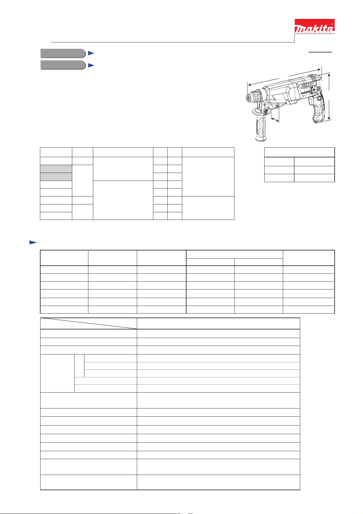
Rotary Hammers 26mm (1")
CONCEPT AND MAIN APPLICATIONS
HR2600/ HR2601 are 26mm (1") 2-mode rotary hammers adapted for
SDS-PLUS bits, featuring compact and lightweight design, enhanced comfort
and better control with ergonomic handle. Model HR2601 is equipped with AVT;
Anti Vibration Technology consisting of Active dynamic vibration absorber
with counterweight and Damper spring. AVT ensures operation with
extremely low vibration, which is much superior to the competitors.
HR2600 series models are available in the variations listed below, including
HR2300 and HR2610 series models developed on the same concept.
Model Operation Mode LED Chuck type
HR2300
HR2600
HR2601
HR2610
HR2611F
HR2310T
HR2610T
HR2611FT
For information of HR2300 and HR2610 series models,
see “
TECHNICAL INFORMATION” of each series.
Capacity
23mm
26mm
23mm
26mm
2 modes
(Rotation only/
Rotation with hammering)
3 modes
(Rotation only/
Rotation with hammering/
Hammering only)
AV T
No
No
Yes
No
Yes
No
Yes
No
No
No
No
Yes
No
NoNo
Yes
Adapted for
SDS-PLUS shank bits
Adapted for
SDS-PLUS shank bits
and Round shank bits*
L
H
W
Dimensions: mm (")
Length (L)
Width (W)
Height (H)
*Round shank bits can also be used by
replacing the factory-mounted chuck with
Quick change drill chuck (keyless).
361 (14-1/4)
77 (3)
209 (8-1/4)
Specification
Voltage (V) Cycle (Hz)
110
120
127 6.6 50/ 60 800 400 550
220
230
240
Specification
No load speed: minֿ¹= rpm
Impacts per minute= minֿ¹
Chuck type
Capacities:
mm (")
Operation mode
Vibration absorption
Variable speed control
Rotation reversing facility
Torque limiter
Double insulation
Power supply cord: m (ft)
Weight according to
EPTA-Procedure 01/2003*2: kg (lbs)
*1 AVT (Anti Vibration Technology); Counterweight mechanism + Damper spring
*2 with side grip
Steel
Wood
Current (A)
7.7
7
3.8
3.7
3.5
Model
TCT bit
Core bit
Diamond core bit
Concrete
50/ 60
50/ 60
50/ 60
50/ 60
50/ 60
Adapted for SDS-PLUS shank bits
(Rotation only/ Rotation with Hammering)
Europe, North America: 4.0 (13.1), Australia, Brazil: 2.0 (6.6),
Other countries: 2.5 (8.2)
Continuous Rating (W)
Input Output
800
---
800
800
800
HR2600/ HR2601
0 - 1,200
0 - 4,600
26 (1)
68 (2-11/16)
80 (3-1/8)
13 (1/2)
32 (1-1/4)
2 modes
No/ Yes (AVT*1)
Yes (by trigger)
Yes
Yes
NoLED Job light
Yes
2.8/ 2.9
(6.2/ 6.3)
400
400
400
400
400
Max. Output (W)
550
550
550
550
550
Page 2

Standard equipment
Depth gauge ............................... 1
Side grip .................................... 1
Dust cup set ................................ 1 (for some countries only)
Plastic carrying case ................... 1
Note: The standard equipment for the tool shown above may vary by country.
Optional accessories
P 2/ 13
SDS-PLUS shank TCT hammer drill bits
Taper shank TCT hammer drill bits
Taper shank adaptor
Cotter
Core bits
Center bits
Core bit adaptor
Rod
Drill chuck ass'y
Chuck adapter assembly
Drill chuck S13
Chuck key S13
Tool holder set
Scraper assembly
Waterproof cover
Quick change drill chuck (keyless)
Dust cups 5 and 9
Hose
Joint 25
Dust cup set
Plastic carrying case
Hammer grease (30g)
Bit grease
Depth gauge
Blow out bulb
Safety goggles
Bull points
Cold chisels
Scaling chisels
Grooving chisels
Hammer service kit
Page 3

P 3/ 13
Repair
CAUTION: Repair the machine in accordance with “Instruction manual” or “Safety instructions”.
[1] NECESSARY REPAIRING TOOLS
DescriptionCode No. Use for
Retaining ring S pliers ST-2N1R003 removing Ring spring 14 and Ring spring 15 from Tool holder complete
Bearing setting pipe 16-8.21R026 assembling Bearing box
Bearing setting pipe 20-12.21R028
Bearing setting plate 10.21R033
Bearing setting plate 15.21R035
Ring spring setting tool A1R164 assembling Oil seal 25
Tip for retaining ring pliers1R212
1/4" Hex. shank bit for M41R228
Pipe 301R232 assembling Oil seal 25
Round bar for arbor 30-1001R252 removing Oil seal 25
V block1R258 assembling Oil seal 25
Bearing extractor1R269 removing Ball bearing 6000LLB / 627DDW
Ring spring 26 setting tool B1R273 removing Cup sleeve / Ball bearing 6806LLU
Round bar for arbor 7-501R281 removing Helical gear 26
1R369 removing/ assembling Spiro lock washer 30
1R388 removing Ring spring 28
Jig for Spiro lock washer
Ring spring extractor
removing Helical gear 26
removing/ assembling Spiro lock washer 30Gear extractor (large)1R045
Use with 1R003
removing M4 Hex socket head bolt
Page 4
Repair
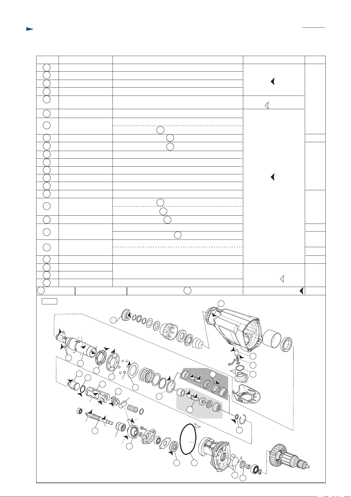
[2] LUBRICATION
Apply the following grease/ lubricant to protect parts and product from unusual abrasion.
Item No. Description Grease/ Lubricant AmountPortion to lubricate
1 Cap 35
Gear housing complete Oil seal 25 on the inside of Gear housing complete
16
2021Push corn Portion that contacts Clutch cam B
Compression spring 5 Periphery
23 O ring 21 Entire surface
26
Steel ball 7.0 (2 pcs.)
28
Tool holder complete
Driving flange
29
32
Flat washer 30
36
Flat washer 30
38 Impact bolt Entire surface
42
O ring 9
44
Striker
45
O ring 17.5
30
Spur gear 51
Piston cylinder
46
47
Guide plate
56
Spur gear 10
Swash bearing 10
58
64
Helical gear 26
65
O-ring 68
70
O ring 26
71
Oil seal 12
HR2601 only40
Fig. 1
Compression spring 20
Lip portion where Bit is to be inserted
Entire surface
(a) Periphery that contacts Driving flange/ Spur gear 51
(b) Inside where 46 Piston cylinder reciprocates
Portion that contacts Spur gear 51/ Pins 6
Portion that contacts Spur gear 51/ Pins 6
30
30
Portion that contacts Inner housing complete
Entire surface
Entire surface
Entire surface
Gear portion
(c) Inside where 44 Striker moves
(d) Periphery that 28 Tool holder complete contacts
Inside that contacts 48 Piston joint
(e) Gear portion
(f) Portion that contacts 58 Swash bearing 10
(g) Interleaved portion to Piston joint
(h) Ball bearing portion
Gear portion that engages with Armature gear shaft
Whole portion
Portion that contacts Sleeve 9
Periphery that contacts 28 Tool holder complete
16
Makita grease RB
No. 00
Makita lubricating oil
VG100
Makita grease RB
No. 00
Makita lubricating
oil VG100
Makita grease RB No. 00
P 4/ 13
a little
2g
a little
19g
in total
3g
a little
3g
3g
a little
a little
26
(a)
28
44
45
(c)
(e)
Clutch cam B
56
(b)
29
(d)
46
(f)
30
1
Pin 6
47
(h)
32
Piston
joint
58
(g)
36
64
HR2601
38
HR2600
65
40
70
20
21
23
42
71
Page 5

Repair
[3] DISASSEMBLY/ASSEMBLY
[3]-1. Bit holder section
P 5/ 13
DISASSEMBLING
(1) Remove Cap 35.
(2) Separate Ring spring 14 from the groove of Tool holder complete using
1R003 with 1R212. (Fig. 2)
Washer 16 on Ring spring 15 is removed.
(3) Remove Ring spring 15 in the same way while pressing down Chuck cover.
(Fig. 3) Then pick up Flat washer 17 and Rubber washer 16 from the space
between Chuck cover and Tool holder complete.
Chuck cover is removed.
(4) Remove two Steel balls 7.0 while pressing down Ring 21. (Fig. 4)
Ring 21, Guide washer and Conical compression spring 21-29 are removed.
Fig. 3
Ring spring 15
(silver)
Chuck cover
ASSEMBLING
Assemble in the reverse order of disassembly. Refer to Fig. 5 for the directions of the components.
Fig. 5
Flat washer 17
Fig. 4
Steel ball 7.0
(2 pcs.)
Fig. 2
Cap 35
Chuck cover
Ring 21
Guide washer
Conical compression
spring 21-29
1R003
1R212
Ring spring 14
(black)
Groove of
Tool holder
complete
Ring spring 14
chamfered
portion
(black)
Ring spring 15
(silver)
Flat washer 17 Rubber
washer 16
chamfered
portion
Chuck coverCap 35 Tool holder
Ring 21 Guide washerWasher 16
flat side
Steel ball
7.0 (2 pcs.)
Conical compression
spring 21-29
concave
side
complete
convex
side
Page 6

P 6/ 13
Repair
[3] DISASSEMBLY/ASSEMBLY
[3]-3. Change lever section
DISASSEMBLING
Insert the tip of thin slot screwdriver into the notch of Gear housing complete,
then lever up one side of Change lever cover B. (Fig. 6)
Lever up the other side of Change lever cover B in the same way,
then remove Change cover lever B. Change lever B can be removed.
ASSEMBLING
(1) Set Change lever B to 45° position as drawn in Fig. 7.
(2) While checking the V-edge of Push corn fits into V-groove of Clutch cam B, insert Change lever B into Gear housing.
(3) After turning Change lever B to hammer drill mode position, put Change lever cover B on Change lever B.
Note: The V-groove of Change lever B has to come on the center of Leaf spring. (Fig. 8)
(4) Be sure to check Change lever B works properly after assembling.
Fig. 7 Fig. 8
center of Leaf spring
Fig. 6
Change lever
cover B
Change lever B
notch of Gear
housing complete
Change lever B
45
°
groove of
Change lever B
V-groove of
Clutch cam B
[3]-4. Armature
REPLACING
(1) Remove three 4x18 Tapping screws and Handle cover.
(2) Slide Brush holder unit to the best position to repair, and move the arms of Spiral springs aside, then separate Carbon
brushes from Commutator. (Fig. 9)
(3) Remove four 4x30 Tapping screws then separate Motor housing from Gear housing complete. Armature is left on
Gear housing at that time. (Fig. 10)
Note: Do not lose Wave washer 15 on the bottom of Motor housing. Do not fail to set it in place when assembling.
(4) Remove Armature ass’y from Gear housing complete by pulling by hand.
Note: Ball bearing 6000LLB of Armature ass’y is held in Inner housing complete with O ring 26. Therefore, it is not
necessary to tap Gear housing complete with Plastic hammer to remove Armature ass’y.
(5) Remove Ball bearings 6000LLB with 1R269.
Remove 627DDW and Insulation washer together at one time with 1R269.
(6) Assemble the components in the reverse order of disassembly after replacing the damaged parts.
Fig. 9 Fig. 10
Ball bearing 6000LLB held with O ring 26 in Inner housing
Gear housing
complete
spiral spring of
Brush holder unit
Insulation washer
Ball bearing 627DDW
Wave washer 15
Motor housing
4x30 Tapping screw
(4 pcs.)
Page 7

Repair
[3] DISASSEMBLY/ASSEMBLY
[3]-5. Torque limiter section
P 7/ 13
REPLACING
(1) Remove Bit holder section.
(2) Remove Change lever section.
(3) Separate Gear housing from Motor housing.
(4) Remove Tool holder complete by tapping the top as drawn in Fig. 11.
Note: Flat washer 30 is located between Tool holder complete and Inner housing complete.
Be careful to lose it.
(5) Set 1R045 and 1R369 to Tool holder complete. (Fig. 12)
(6) Compress Compression spring 32 (Fig. 13), then separate Spiro lock washer 30 from
Tool holder complete by sliding a thin slotted screwdriver from the upper end as drawn
in Fig. 14. The components are disassembled. (Fig. 15)
Fig. 13Fig. 12 Fig. 14
1R369
Tool holder complete
1R369
Fig. 15
Tool holder complete
Spur gear 51
Flat washer 30 (thicker than the others) Flat washer 30 (thin)
1R045
Compression spring 31
Fig. 11
Upper end of
Spiro lock
washer 30
thin
slotted
screwdriver
Tool holder
complete
1R369
Steel ball 4 (4 pcs.) Pin 6
Driving flange Compression spring 31
(6 pcs.)
Spiro lock washer 30
Page 8

P 8/ 13
Repair
[3] DISASSEMBLY/ASSEMBLY
[3]-6. Impact bolt in Tool holder complete
DISASSEMBLING
(1) Put 1R388 into Tool holder complete then push 1R388 in vise with the access holes on Tool holder complete parallel
to Vise. (Fig. 16)
O-ring case A/ B is moved toward the top of Tool holder complete, and therefore, Ring spring 28 can be relieved from
O-ring case A/ B.
(2) When the end gap of Ring spring 28 is in the access hole, slide it with slotted screwdriver until it is completely hidden.
(3) Using slotted screwdriver, tap Ring spring 28 through the two access holes alternately to push it out of the inner groove
of Tool holder complete.
(4) The components are removed by tapping with phillips screwdriver and plastic hammer from bit installation side of
Tool holder complete. (Fig. 17)
Fig. 16
The directions of two access holes on Tool holder complete
have to be parallel to Vise.
90
°
Fig. 17
Bit
installation
side
Vise Vise
1R388
1R388 O-ring case A (HR2600) / B (HR2601)
holes on both side of Tool holder complete
to access inside
HR2600 HR2601
slotted
screwdriver
inner groove of Tool holder complete
Ring spring 28
Bit
installation
side
Sleeve 9A Sleeve 9B
Impact bolt A
Ring 10A
Cushion ring 12
O-ring case A O-ring case B
O ring 9 O ring 9
Ring spring 28 Ring spring 28
Note: Refer to Fig. 18A/ 18B for the details.
Impact bolt A
Inner
housing
complete
side
Washer 10
Compression
spring 20
Inner
housing
complete
side
Page 9

Repair
[3] DISASSEMBLY/ASSEMBLY
[3]-6. Impact bolt section in Tool holder complete (cont.)
ASSEMBLING
(1) Assemble Impact bolt section to Tool holder complete as drawn in Fig. 18A/ 18B.
Fig. 18A
Impact bolt section in Tool holder complete for HR2600
Tool holder complete (140264-5)
Bit
installation
side
Sleeve 9A
Ring 10A
Cushion ring 12
P 9/ 13
O ring case A with
O ring 9 fit inside Impact bolt A
Inner housing
complete side
Note: These components
are directional.
Fig. 18B
Impact bolt section in Tool holder complete for HR2601
Tool holder complete (140265-3)
Bit
installation
side
Note: These components
are directional.
(2) Push Ring spring 28 into the inner groove of Tool holder complete as drawn in Fig. 19.
Note: Do not reuse the removed Ring spring 28 if it is deformed or damaged.
Fig. 19
Note: 1. Use an extra Piston cylinder as a jig. Never use Piston cylinder that is to be assembled to the machine.
2 2 The end gap of Ring spring 28 must not be located at the two holes of Tool holder complete.
Piston cylinder
as a jig
end gap
ø9mm
[cross-sectional view]
Sleeve 9B Washer 10 Compression
Impact bolt A
ø9mm
[cross-sectional view]
Note: 1
Inner groove of
Tool holder
complete
ø9.5mm
spring 20
ø9.5mm
HR2600
Piston cylinder as a jig
O ring case B with
O ring 9 fit inside
Ring spring 28
Tool holder
complete
Note: 2
Ring spring 28
hole
Tool holder
complete
end gap
Ring spring 28
hole
Inner groove of
Tool holder complete
[Correct] [Wrong]
Ring spring 28
O ring case A
HR2601
Piston cylinder as a jig
O ring case B
Page 10

P 10/ 13
Repair
[3] DISASSEMBLY/ASSEMBLY
[3]-7. Swash bearing section
DISASSEMBLING
(1) Disassemble Motor housing section, Gear housing section and Inner housing section. As for HR2601, remove two
M4x12 Hex socket head bolts. And then separate Counter weight section from Inner housing complete. (Fig. 20)
(2) Remove two M4x16 Hex socket head bolts with hex wrench 3 and 1R228. (Fig. 21)
Then pull Swash bearing section out of Inner housing complete. (Fig. 22)
(3) Remove Ball bearing 606ZZ from Gear housing complete using the removed Swash bearing section. (Fig. 23)
(4) Receive Clutch cam B on 1R035 and press Spur gear 10 out of Clutch cam B.
The swash bearing section can be removed as drawn in Fig. 24.
Fig. 20
For HR2601 only
M4x12 Hex socket
head bolt (2 pcs.)
Plate
Counter weight
Pin 6
Weight holder guide
Fig. 21
M4x16 Hex socket
head bolt (2 pcs.)
Note: These are thread
locking screws.
Do not reuse them without applying
ThreeBond 1321B/ 1342 or Loctite 242..
Fig. 22
Inner housing complete
Piston cylinder
Push Piston cylinder into Inner housing
complete to tilt Swash bearing 10.
Fig. 23
Insert shaft portion of Spur gear 10
to the hole of Ball bearing 606ZZ,
and tilt it back and forth.
Swash bearing 10
Pull Swash bearing section horizontally
with Swash bearing 10 kept tilted, and
remove the pole of Swash bearing 10
toward the tilted direction.
Swash bearing section
(Note: Ball bearing 606ZZ is left in Gear housing complete.)
Tap Gear housing complete with plastic hammer.
Ball bearing 606ZZ is removed together with
Swash bearing section.
Fig. 24
Swash bearing
section
Spur gear 10 Clutch cam B
Ball bearing 606ZZ
in Gear housing
complete
Swash bearing 10
Flat washer 8
Ball bearing 606ZZ
Bearing retainerBearing box Ball bearing 608ZZ
Helical
gear 26
Page 11

Repair
[3] DISASSEMBLY/ASSEMBLY
[3]-7. Swash bearing section (cont.)
ASSEMBLING
(1) Pressfit Ball bearing 608ZZ into Bearing box.
(2) Put Clutch cam B, Swash bearing 10, Flat washer 8 and Bearing box to Spur gear 10 in order,
then secure them using 1R033, 1R026 and arbor press.
(3) Fit Bearing retainer in Bearing box, then pressfit Helical gear 26 to the shaft of Swash bearing section.
Be careful of the directions of Bearing box and Helical gear 26. (Fig.25)
Fig. 25
The center is projected higher than that of the reverse.
Face the projection to Bearing retainer.
Helical gear 26
P 11/ 13
Bearing box with
Ball bearing 608ZZ
Viewed from
Swash bearing 10 side
Bearing retainer
The wrong installation causes the top of
Bearing retainer to bump against
Armature shaft.
[3]-8. How to assembly of Piston cylinder section to Swash bearing section
(1) Assemble Guide plate and Piston joint to Piston cylinder. Align the holes of Piston joint to the installed direction of
Swash bearing 10. (Fig. 26)
(2) Set Flat washer 14 and Compression spring 14 on the boss of Inner housing complete. (Fig. 26)
(3) Put the opposite end of Compression spring 14 on Guide plate, then push Piston cylinder into the bottom of Inner
housing complete and insert the pole of Swash bearing 10.
(4) Assemble Striker with O ring 17.5 to Piston cylinder. Refer to Fig 1.
Fig. 26
Note: Air release hole on
Piston cylinder can be
positioned at either
side. (no fixed position)
Guide plate
Piston joint
Guide plate
Compression spring 14
the installed direction of
Swash bearing 10
Boss of Inner housing
complete
Turn the pole of
Swash bearing 10.
[3]-9. How to assemble Gear housing to Inner housing
(1) Check that Clutch cam B is engaged with Swash bearing 10. (Fig. 27)
(2) Assemble Gear housing complete to Inner housing complete.
Flat
washer 14
Viewed from Swash bearing 10
installation side
Fig. 27
Swash bearing 10
Clutch
cam B
Check here.
Page 12

Repair
[4] Maintenance program
It is recommended to replace the following parts at the same time when replacing Carbon brushes. (Fig. 28)
Note: Be sure to put Makita grease RB No. 00 to the specific portions. (Fig. 1)
Fig. 28
P 12/ 13
Cap 35
(286288-8)
Steel ball 7 (2 pcs.)
(216022-2)
O ring 17.5
(213258-4)
Ring spring 14
(233989-9)
Ring spring 15
(233992-0)
HR2600
Cushion ring 12
Rubber washer 16
(424364-2)
HR2601
Ring spring 28
(233979-2)
(424267-0)
O ring 9
(213073-6)
Page 13

Circuit diagram
Fig. D-1
Noise suppressor
Switch*
(if used*)
P 13/ 13
Brush holder unit
Strain relief
Power supply cord
* To comply with the electromagnetic compatibility-requirement,
Switch equipped with Noise suppressor is used for some countries.
Wiring diagram
Fig. D-2
Lead wires (black, white) must be tight between
Brush holder unit and Lead wire holders.
Fix black
lead wire
in this lead
wire holder.
Fix white lead wire in this lead wire holder.
Switch
Strain relief
Noise suppressor
(if used)
 Loading...