

Page 1
T
ECHNICAL INFORMATION
Models No.
HR2450FT, HR2450T
PRODUCT
P 1 / 22
Description
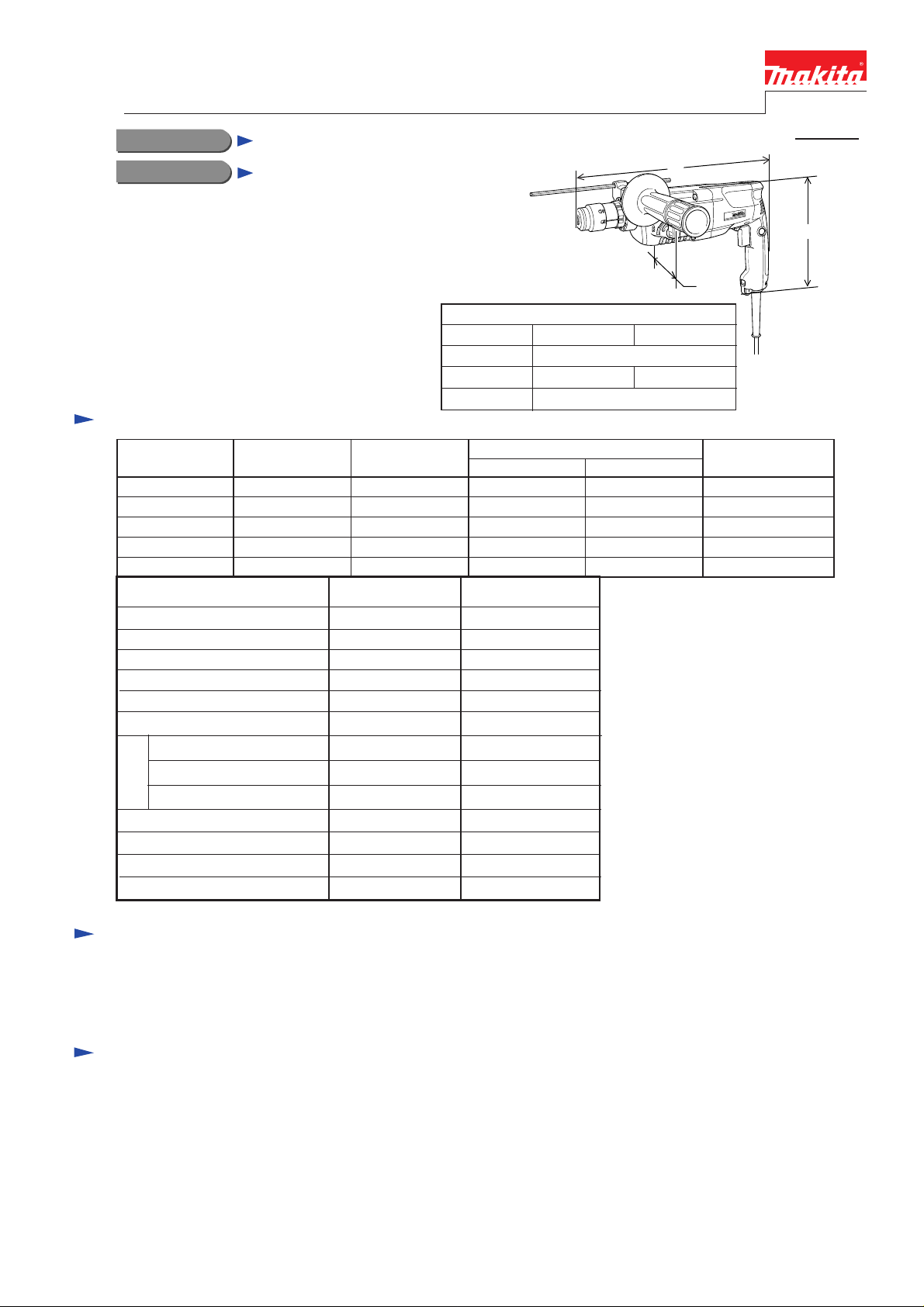
24mm (15/16") Rotary Hammer
CONCEPTION AND MAIN APPLICATIONS
The above models are the advanced version of MAKITA's
famous 3 -mode rotary hammer HR2450.
Each new model features :
HR2450T : possible to quickly change from
the chuck for SDS-plus to keyless
drill chuck mutually without any tool
HR2450FT : equipped with built in job light
in addition to HR2450T's feature
Specification
Voltage (V) Cycle (Hz)
110 7.5
120
220
230
240
Model No. HR2450FT HR2450T
No load speed : (min -1= rpm)
Blows per min, :(bpm=min -1)
Single blow energy ( J )
Variable switch
Reverse switch
Bit shank
Concrete : mm (")
Steel. : mm (")
Wood : mm (")
Capacity
Protection against electric shock
Built in job light
Cord length : m ( ft )
Net weight :Kg (lbs )
Current (A)
6.7
3.7
3.6
3.4
50 / 60
50 / 60
50 / 60
50 / 60
50 / 60
0 - 1,100 0 - 1,100
0 - 4,500 0 - 4,500
2.7 2.7
Yes Yes
Yes
SDS plus type
* 24 (15/16 )
13 (1/2 ) 13 (1/2 )
32 (1-1/4 ) 32 (1-1/4 )
double insulation double insulation
Yes No
** 4 (13.1) ** 4 (13.1)
2.6 (5.7) 2.6 (5.7)
Model No.
Length ( L )
Height ( H )
Width ( W )
Input Output
Yes
SDS plus type
* 24 (15/16 )
Dimensions : mm ( " )
HR2450FT HR2450T
384 (15-1/8)
212 (8-3/8) 204 (8)
72 (2-13/16)
Continuous Rating (W)
780
780
780
780
780
370
370
370
370
370
* 25mm (1") for USA.
** 2.5m (8.2 ft) for Asia
** 2.0m (6.6 ft) for Australia
L
H
W
Max. Output(W)
650
650
650
650
650
Standard equipment
* Stopper pole ........................ 1 pc.
* Quick change drill chuck ..... 1 pc.
* Plastic carrying case ............ 1 pc.
< Note > The standard equipment for the tool shown may differ from country to country.
* Side grip ..................... 1 pc.
Optional accessories
* T.C.T hammer drill bits 5.5mm - 24mm
(7/32" - 15/16")
* Bull point 14mm (9/16")
* Cold chisel 20mm (13/16")
* Scaling chisels 38mm and 50mm
(1-1/2" and 2")
* Grooving chisels 8mm and 12mm
(5/16" and 1/2")
* Scraper assembly
* Core bits
* Center bits
* Core bit adaptor
* Rod
* Core bits (dry type)
* Taper shank adaptor
* Taper shank T.C.T.hammer drill bits
* SDS plus hammer chuck set
* SDS plus adapter
* Dust cups 5 and 9
* Safety goggle
* Bit grease
* Blow out bulb
* Dust extractor attachment
* Hammer service kit
Page 2
Repair
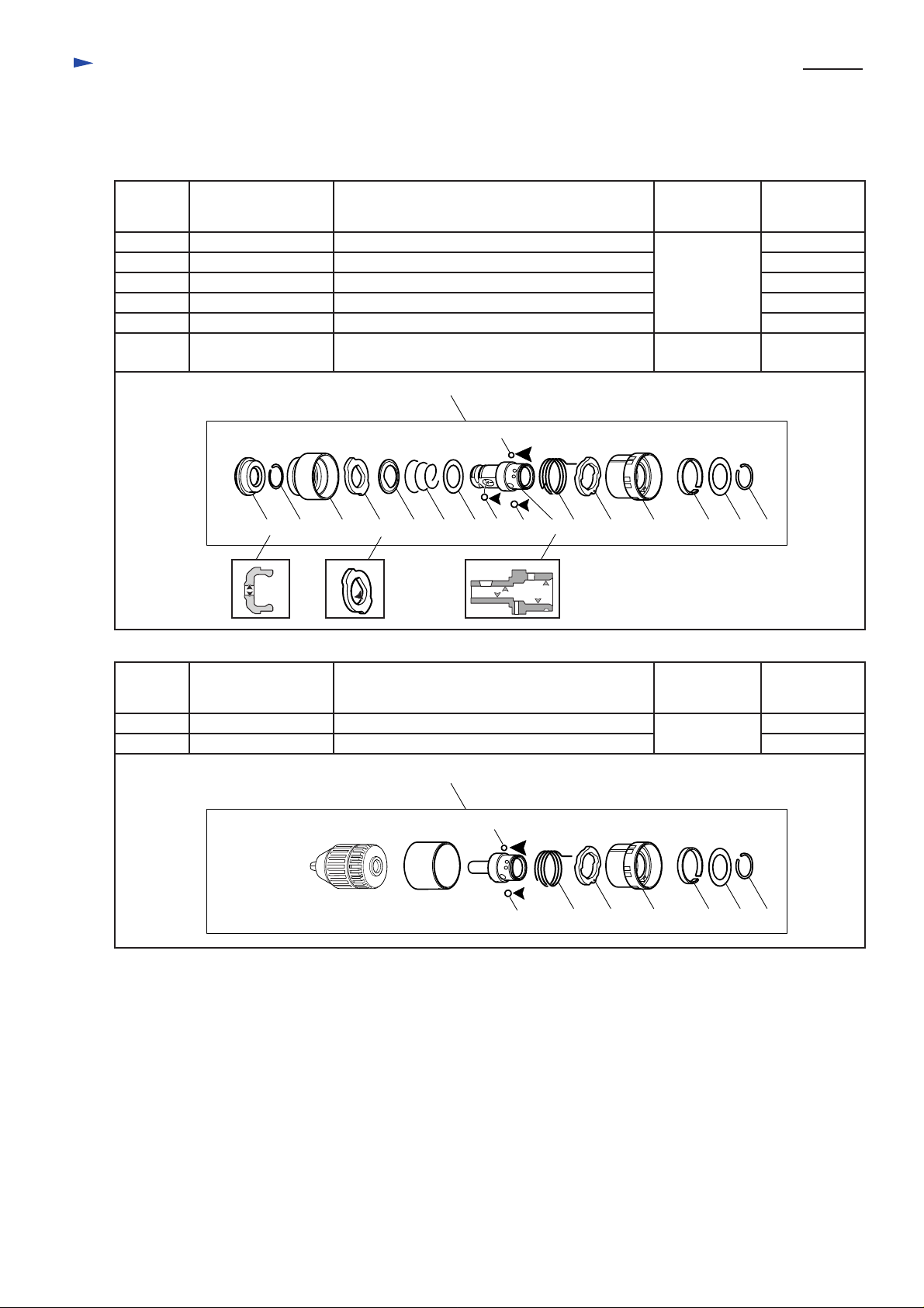
< 1 > Lubrication to the bit holder section
Apply MAKITA grease to the following portions to protect parts and product from unusual abrasion.
* MAKITA grease RA No.1 to the portions designated with black triangle.
* MAKITA grease FA No. 2 to the portions designated with gray triangle.
* MAKITA hammer oil to the portions with white triangle.
P 2 / 22
Position
No.
95 Cap 35 Inner lip of bit inserting side.
98 Stopper
99 Steel ball 7
104
108
103
Parts item
Steel ball 6
Steel ball 5.0
Tool holder
95
Portion to be lubricated
The inside where (103) tool holder contacts.
Whole part
Whole part
Whole part
The inside where (21) tool holder guide contacts.
Quick change chuck assembly
96 97
98
100
101
102
108
99
MAKITA
grease
MAKITA
grease RA No.1
MAKITA
grease FA No.2
103104
105
106
107
109
Amount : g
(oz)
1.0 (0.04)
1.0 (0.04)
1.0 (0.04)
1.0 (0.04)
1.0 (0.04)
1.0 (0.04)
111
110
Position
No.
104
108
Parts item
Steel ball 6
Steel ball 5.0
Portion to be lubricated
Whole part
Whole part
Quick change drill chuck assembly
108
104
105
106
MAKITA
grease
MAKITA
grease RA No.1
107
109
Amount : g
(oz)
1.0 (0.04)
1.0 (0.04)
111
110
Page 3
Repair
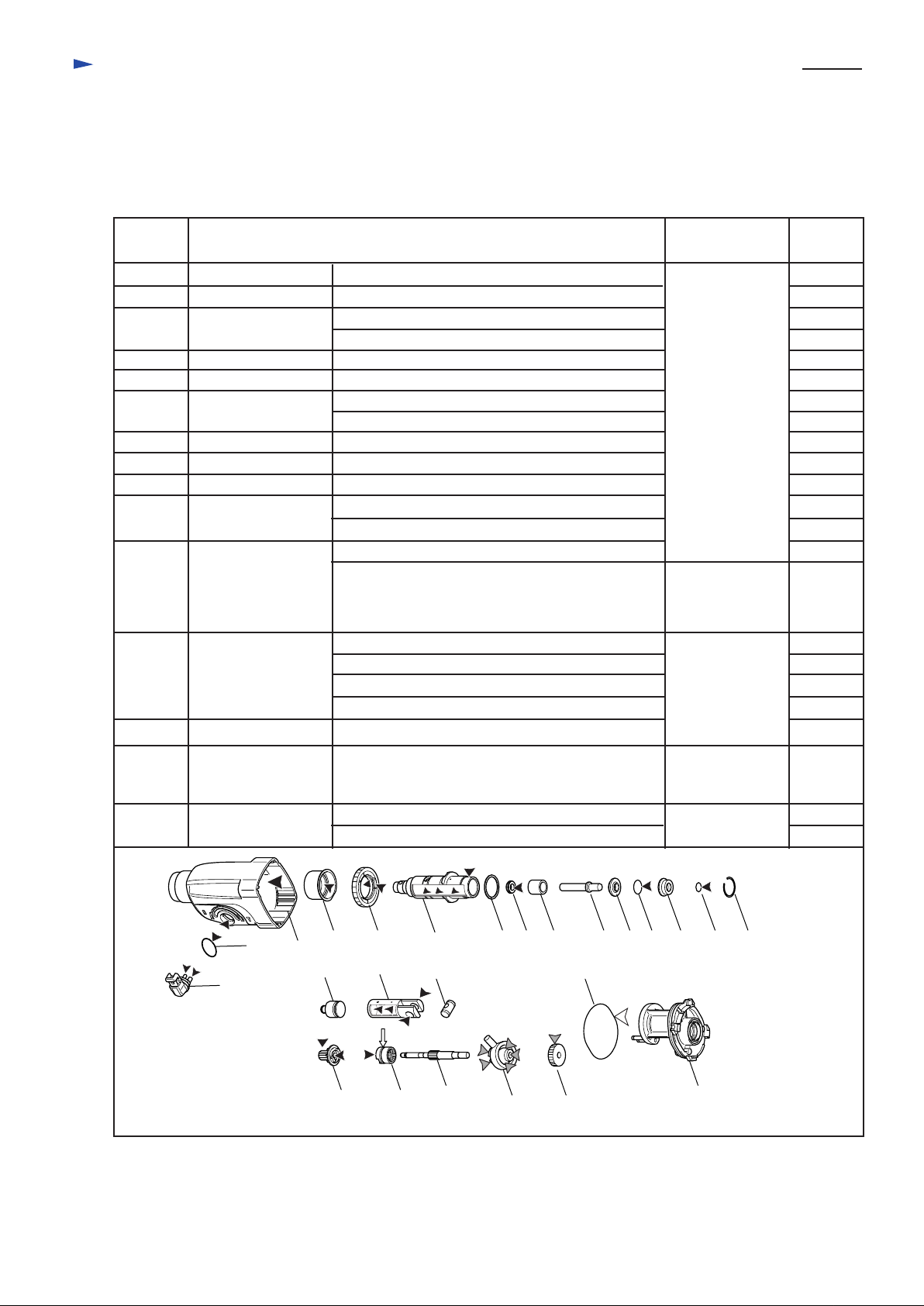
< 2 > Lubrication to the machine parts
Apply MAKITA grease to the following portions to protect parts and product from unusual abrasion.
* MAKITA grease RA No.1 to the portions designated with black triangle.
* MAKITA grease FA No. 2 to the portions designated with gray triangle.
* MAKITA hammer oil to the portions designated with white triangle.
* Disulphide molybdenum alloyed grease to the portions designated with arrow.
P 3 / 22
Position
No.
12
13
14
15
19
21
23
26
28
32
39
41
42
Parts item
Change lever Top of the pins
O ring 17
Gear housing
Needle bearing
Spur gear 51
Tool holder guide
X ring 9
O ring 15
O ring 9
Piston cylinder
Clutch cam
Swash bearing 10
Helical gear 26
Portion to be lubricated
Whole portion
Inner portion for the mechanical parts
Groove for mounting (13) O ring 17
Inner ring
Inner portion where (21) tool holder guide contacts.
Inner portion where (32) piston cylinder contacts.
The portion where (49) inner housing contacts.
Inner hole for reciprocating (24) impact bolt.
Whole portion
Whole portion
Accepting hole for (34) piston joint
Inner portion where (30) striker reciprocates.
Convex portion of cam
Whole of groove portion
Accepting hole for (40) cam shaft
The surface where (42) helical gear 26 contacts.
Convex portion of cam
The portion where balls are installed
Teeth portion
MAKITA
grease
MAKITA
grease RA No.1
Disulfide molybdenum alloyed
grease
MAKITA
grease FA No.2
Amount
: g(oz)
1.0 (0.04)
1.0 (0.04)
55 (1.91)
1.0 (0.04)
1.0 (0.04)
1.0 (0.04)
1.0 (0.04)
1.0 (0.04)
1.0 (0.04)
1.0 (0.04)
1.0 (0.04)
1.0 (0.04)
1.0 (0.04)
1.0 (0.04)
0.5 (0.02)
1.0 (0.04)
1.0 (0.04)
1.0 (0.04)
4.0 (0.14)
48
80
O ring 68
Spur gear 10
13
12
Whole portion
Teeth portion
Accepting hole for (40) cam shaft
14
30
80 39
1915
32
21
34 48
40
22 23 24 25 26 27 28 2993
41 42
MAKITA
hammer oil XLD
MAKITA
grease RA No.1
49
1.0 (0.04)
1.0 (0.04)
1.0 (0.04)
Page 4
Repair
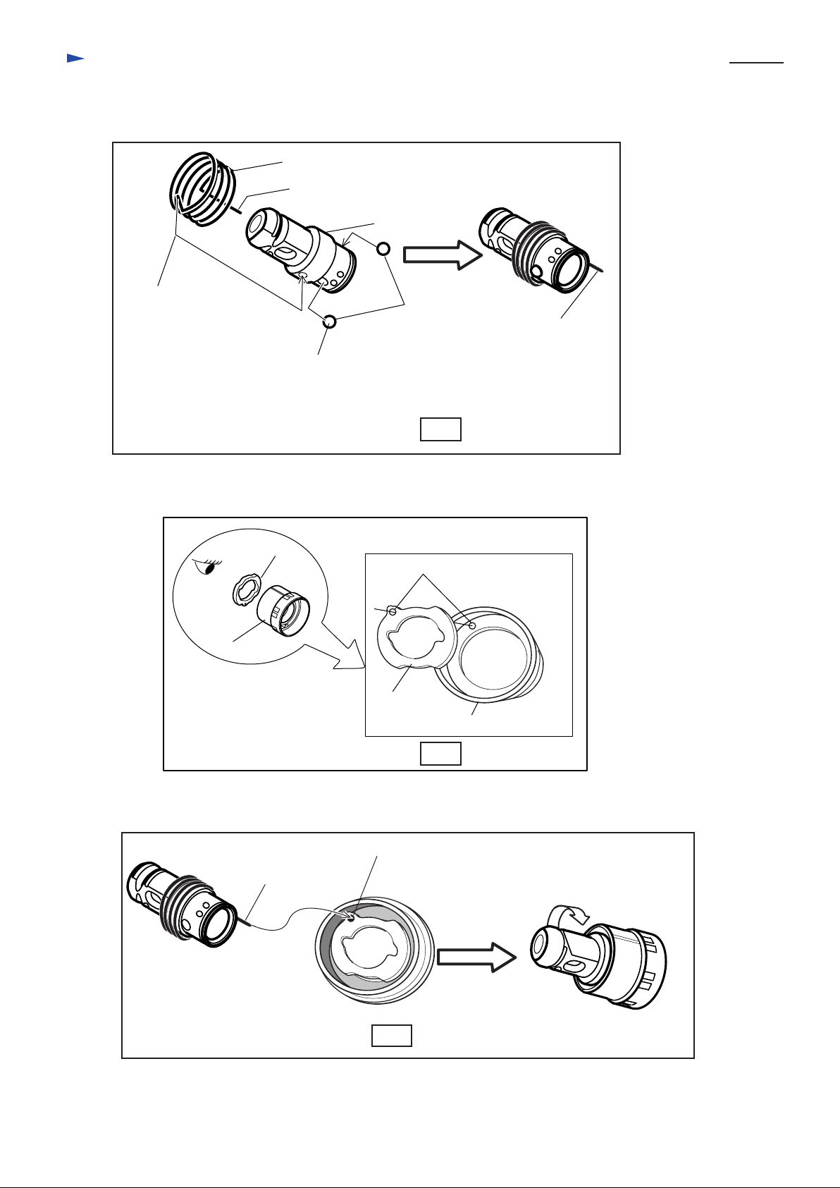
< 3 > Assembling quick change chuck
(1) Mount torsion spring 31 by inserting pin of torsion spring 31 into the hole of tool holder and mount 2 pcs. of
steel ball 6.0 to tool holder. See Fig. 1.
Torsion spring 31
Long pin of torsion spring 31
Tool holder
P 4 / 22
Short Pin of
torsion spring 31
Coat the steel ball 6.0 with MAKITA grease N No.1,
before mounting.
Now the steel ball sticks on the hole of tool holder.
(2) Mount change ring to the inside of change cover while aligning the hole of change ring with the hole of
change cover. See Fig. 2.
Change ring
Change cover
Steel ball 6.0
Long Pin of
torsion spring 31
Fig. 1
Holes for pin of torsion spring 31
Change ring
Change cover
Fig. 2
(3) Mount tool holder to change cover by passing the long pin of torsion spring 31 through the holes of change ring
and change cover. And turn the tool holder approx. by 75
Long pin of
torsion spring 31
The hole of change ring
aligned with the hole of
change cover
Fig. 3
° . See Fig. 3.
Approx. 75
°
Page 5
Repair
(4) Mount steel ball 5.0 to the space between change cover and tool holder. And secure the steel ball 5.0
with leaf spring. See Fig. 4.
(5) Mount flat washer 24. See Fig. 5.
(6) Secure flat washer 24 with ring spring 21. See Fig. 6.
Steel ball 5.0
Flat washer 24
Flat washer 24
P 5 / 22
Leaf spring
Fig. 4
(7) Mount flat washer 2. And then mount steel ball 7.0 to the hole of tool holder. See Fig. 7.
Coat the steel ball 7.0 with MAKITA grease N No.1, before mounting.
Now the steel ball sticks on the hole of tool holder.
(8) Mount conical compression spring 21-29, guide washer and stopper. See Fig. 8.
(9) Mount chuck cover. See Fig. 9.
(10) While sliding the chuck cover in the direction designated with arrow, mount ring spring 19. See Fig. 10.
Now the parts mounted in Fig. 7, Fig. 8 and Fig.9 have been secured with the ring spring 19.
(11) Mount cap 35 as illustrated in Fig. 11.
Flat washer 21
Steel ball 7.0
Fig. 7
If it is difficult to mount
leaf spring with your hand,
mount it with "retaining
ring plier for shaft."
Stopper
Guide washer
Conical
compression
spring 21-29
Fig. 8
Leaf spring
Chuck cover
Fig. 5
Ring spring 21
Fig. 6
Slide chuck
cover.
Cap 35
Ring spring 19
Fig. 11
Fig. 9
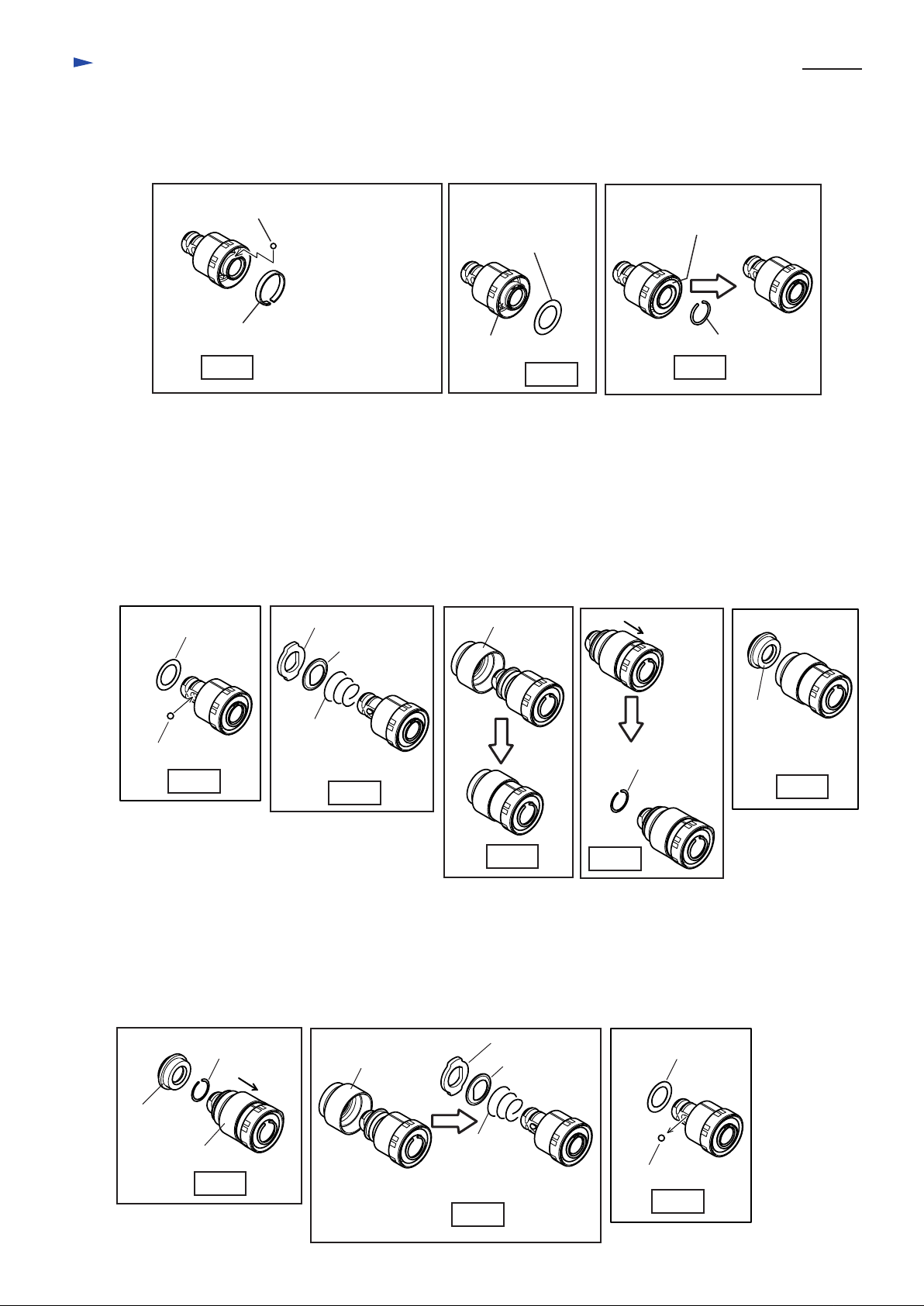
< 4 > Disassembling quick change chuck
(1) Remove cap 35 while sliding chuck cover in the direction designated with arrow. See Fig. 12.
(2) Remove ring spring 19, keeping the chuck cover in the slid position. See Fig. 12.
(3) Remove chuck cover, stopper, guide washer, conical compression spring 21-29. See Fig. 13.
(4) Remove steel ball 7.0 and flat washer 21. See Fig. 14.
Stopper
Guide washer
Conical
compression
spring 21-29
Fig. 13
Cap 35
Chuck cover
Ring spring 19
Fig. 12
Chuck cover
Fig. 10
Flat washer 21
Steel ball 7.0
Fig. 14
Page 6
Repair
(5) Remove ring spring 21. Then, flat washer 24 can be removed from tool holder. See Fig. 15.
(6) Remove leaf spring with No.1R212 "Retaining Ring Plier". Then, steel ball 5.0 can be removed from tool holder.
See Fig. 16.
If it is difficult to remove leaf spring with No.1R212 "Retaining Ring Plier", slightly knock the change cover
to the working table several times. Then, leaf spring can be removed. See Fig. 16A.
(7) Remove tool holder and change ring from change cover. See Fig. 17.
(8) Remove torsion spring 31 and steel ball 6.0 from tool holder. See Fig. 18.
P 6 / 22
Flat washer 24
Ring spring 21
Tool holder
Change ring
Change cover
Fig. 17
Leaf spring
Fig. 15
Flat washer 24
Steel ball 5.0
Leaf spring
Fig. 16
Torsion spring 31
Tool holder
Steel ball 6.0
Fig. 18
Change
cover
Leaf spring
Fig. 16A
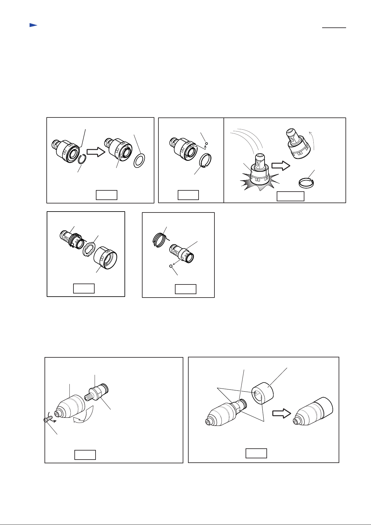
< 5 > Assembling quick change drill chuck
(1) Mount keyless drill chuck 13 to chuck holder by turning it clockwise. See Fig. 19.
(2) Secure the keyless drill chuck by turning flat head screw M6x22 counter-clockwise. See Fig. 19.
(3) Mount the keyless drill chuck, while aligning the flat portion of chuck holder with the flat portion of spacer.
See Fig. 20.
Spacer
Keyless
drill chuck 13
Flat head
screw M6x22
Fig. 19
Chuck holder
Hold this part with
vise firmly.
Fastening torque for
keyless drill chuck 13
is 36 - 46N.m.
Chuck holder
Align the flat
portion.
Align the flat
portion.
Fig. 20
Page 7
Repair
(4) Mount torsion spring 31 to the chuck holder by inserting its short pin into the pin hole of chuck holder.
See Fig. 21.
(5) Mount change ring to the inside of change cover while aligning the hole of change ring with the hole of
change cover. See Fig.22.
(6) Keyless drill chuck 13 to change cover by passing the long pin of torsion spring 31 through the holes of change ring
and change cover. And turn the keyless drill chuck 13 approx. by 75
(7) Mount steel ball 5.0 to the space between change cover and chuck holder. And secure the steel ball 5.0
with leaf spring. See Fig. 24.
(8) Mount flat washer 24. See Fig. 25.
(9) Secure flat washer 24 with ring spring 21. See Fig. 26.
Change ring
° . See Fig. 23.
Holes for pin of torsion spring 31
P 7 / 22
Insert the short pin
of torsion spring 31
into the pin hole of
chuck holder.
Fig. 21
Long pin of
torsion spring 31
Change cover
The hole of change ring
aligned with the hole of
change cover
Fig. 23
Change ring
Fig. 22
Approx. 75
Change cover
°
Steel ball 5.0
Leaf spring
If it is difficult to mount
leaf spring with your hand,
mount it with "retaining
ring plier for shaft."
Fig. 24
Leaf spring
Flat washer 24
Fig. 25
Flat washer 24
Ring spring 21
Fig. 26
Page 8

Repair
< 6 > Disassembling quick change drill chuck
(1) Remove ring spring 21. Then, flat washer 24 can be removed from chuck holder. See Fig. 27 and Fig. 28.
(2) Remove leaf spring with No.1R212 "Retaining Ring Plier". Then, steel ball 5.0 can be removed from chuck holder.
See Fig. 29.
If it is difficult to remove leaf spring with No.1R212 "Retaining Ring Plier", slightly knock the change cover
to the working table several times. Then, leaf spring can be removed. See Fig. 29A.
(3) Remove keyless drill chuck with spacer and change ring from change cover. See Fig. 30.
Flat washer 24
Leaf spring
P 8 / 22
Ring spring 21
Fig. 27
Steel ball 5.0
Change
Leaf spring
Fig. 29
(4) Remove torsion spring 31 from chuck holder. See Fig. 31.
(5) Remove spacer from chuck holder. See Fig. 32.
(6) Remove flat head screw M6x22 by tuning it clockwise. See Fig. 33.
(7) Remove keyless drill chuck 13 by tuning it counter clockwise. See Fig. 34.
cover
Flat washer 24
Fig. 28
Leaf spring
Fig. 29A
Keyless
drill chuck
Spacer
Change ring
Change cover
Fig. 30
Torsion spring 31
Fig. 31
Spacer
Fig. 32
Keyless
drill chuck
Keyless
drill chuck 13
Flat head
screw M6x22
Fig. 33
Chuck holder
Hold this part with
vise firmly for easy
removing of keyless
drill chuck.
Fig. 34
Page 9

Repair
< 7 > Disassembling change lever
(1) Separate cap from change lever. See Fig. 35.
(2) Fully turn change lever in the direction of drill mode. Then, change lever can be pulled out from gear housing.
See Fig. 36.
Gear housing
Cap
Change
lever
P 9 / 22
Gear housing
Cap
Gear housing
< 8 > Assembling change lever
(1) Apply grease to the pin of change lever and O ring 17. Refer to "< 2 > Lubrication to the machine parts" in page 3.
(2) Assemble compression spring 3 and lock button to change lever. And temporarily assemble cap to the position
illustrated in Fig. 37 in order to stop springing off of lock button. Do not forget to assemble O ring 17. See Fig. 37.
(3) Insert the change lever in which compression spring 3 and lock button have been temporarily fixed with cap, into
the assembling hole of gear housing. See Fig. 38. The change lever can not be inserted completely in this stage.
(4) Pressing the change lever, turn it in the direction of drill mode. Then, it can be inserted completely
in any position of area B. See Fig. 39.
(5) Turn the change lever to the area C. See Fig. 39. And assemble cap completely to the original position
of change lever, by pressing to gear housing side.
Fig. 35
Lock button
Compression spring 3
Fig.36F
Fig. 36
< Note >
Be careful, not to lose lock button
and compression spring 3.
They can easily spring off.
O ring 17
Lock button
Compression spring 3
Change lever
Cap
Lock button
Compression
spring 3
Change lever
Fig. 37
O ring 17
Cap, assembled
temporarily
A
Insert the change lever
within the area A.
Fig. 38
Cap assembled
completely by
C
B
If the change lever can not be inserted completely
in any position of area B, pressing lock button, turn it
to the direction of drill mode again in order
to insert completely in any position of area B.
pressing.
Compression
spring 3
Change lever
Fig. 39
Lock button
Page 10

Repair
< 9 > Disassembling armature
1. Remove handle cover by unscrewing 3 pcs. of tapping screw 4 x 45. And remove carbon brushes
as illustrated in Fig. 40.
2. Separate gear housing together with armature, from motor housing by unscrewing 4 pcs. of tapping screw 4 x 45
as illustrated in Fig. 41.
3. Slightly hitting the edge of gear housing with plastic hammer, remove armature from inner housing assembled in
gear housing. See Fig. 42.
4. Ball bearings of fan side and commutator side can be removed with No.1R269 "Bearing extractor (small)".
See Fig. 43.
Tapping s
Brush holder
crew 4 x 45 : 4 pcs.
P 10 / 22
Brush
holder
Carbon brush
Handle
cover
Gear housing
Fig. 40
Inner housing
Inner housing
Carbon brush
Tapping screw
4 x 25 : 3 pcs.
Gear housing
Motor housing
Fig. 41
Ball bearing
Armature
No.1R269
"Bearing extractor (small)"
Plastic hammer
Plastic hammer
Fig. 43
Fig. 42
Page 11

Repair
< 10 > Disassembling tool holder guide section
( 1 ) After removing change lever ( See page 9), separate gear housing from motor housing as illustrated
in Fig. 40 and Fig. 41 in page 10.
( 2 ) Remove inner housing as illustrated in Fig. 44.
( 3 ) Separate tool holder guide section from inner housing. See Fig. 45.
( 4 ) Remove ring spring 29, while pressing washer 31 which covers ring spring 29, toward the spur gear 51 side.
See Fig. 46 and 47. After removing ring spring 29, reduce pressure on the washer 31 slowly.
( 5 ) Remove washer 31, compression spring 32 and spur gear 51 form tool holder guide. See Fig. 48.
Tool holder
guide section
Flat washer 28
Piston cylinder
Inner housing
Tool holder
guide section
Inner
housing
P 11 / 22
Swash bearing
section
No. 1R306
Ring spring
extractor
Retaining ring
plier
Fig. 44
Fig. 46
Round bars
for arbor
Ring
spring 29
Washer 31
Swash bearing
section
Retaining
ring plier
Fig. 47
Fig. 45
Ring
spring 29
Washer 31
Washer 31
Compression
spring 32
Spur gear 51
Tool
holder guide
Fig. 48
< 11 > Assembling tool holder guide section
( 1 ) Apply grease to spur gear 51 and tool holder guide referring to "< 2 > Lubrication to the machine parts"
in page 3.
( 2 ) Mount spur gear 51, compression spring 32 and washer 31. See Fig. 48.
( 3 ) Pressing the washer 31 toward the spur gear 51 side, with arbor press, mount ring spring 29 as illustrated
in Fig. 47 and Fig. 46. And mount flat washer 28 to the position illustrated in Fig. 45.
( 4 ) Insert piston cylinder of swash bearing section into tool holder guide. And insert tool holder section into inner
housing as illustrated in Fig. 45.
Page 12

Repair
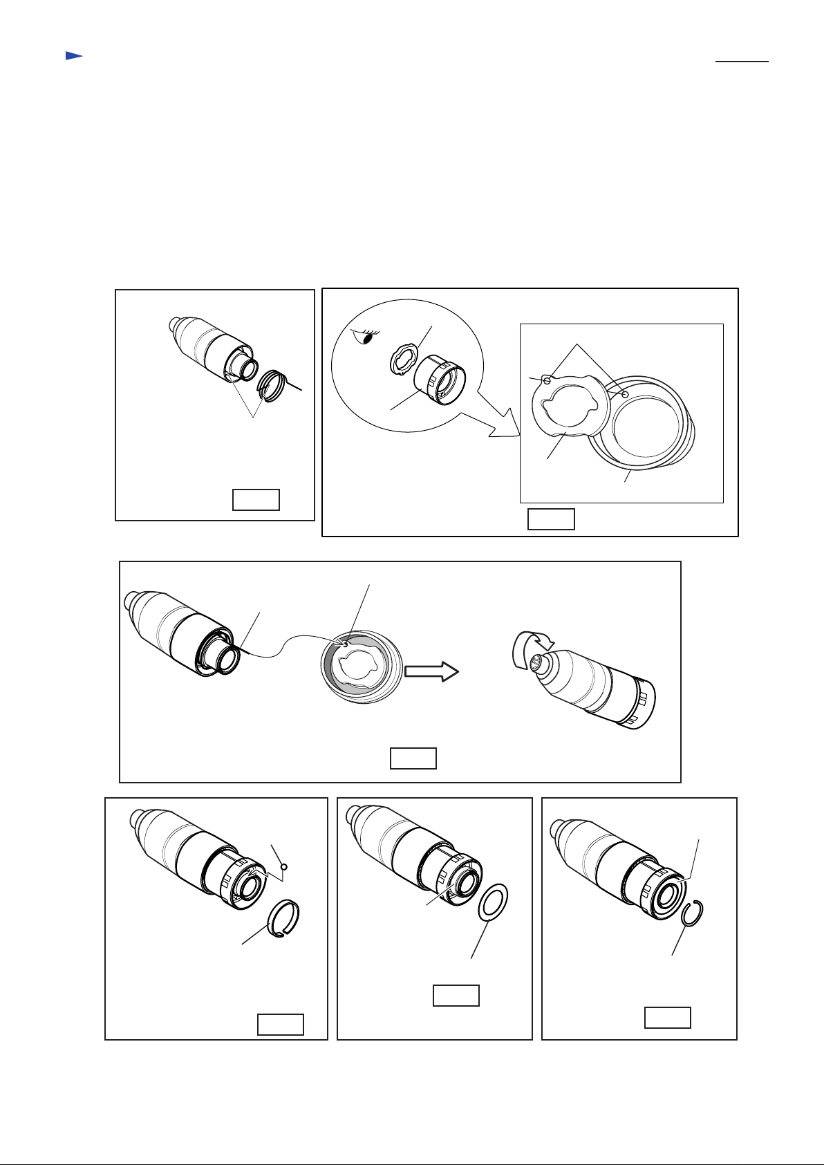
< 12 > Disassembling impact bolt
( 1 ) Referring to "< 10 > Disassembling tool holder guide section" in page 11, remove ring spring 29, washer 31,
compression spring 32 and spur gear 51 from tool holder guide. See Fig. 44, 45, 46, 47 and Fig. 48.
( 2 ) Push the cut portion of ring spring 28 to the out side of the hole as illustrated in Fig. 49 and Fig. 49A.
Ring spring 28 showing its
cut portion
Tool holder
or
Chuck holder side
Ring spring
Inner
housing side
P 12 / 22
O ring case
Push the cut portion to
the out side of the hole.
Fig. 49
Tool holder
or
Chuck holder side
Impact bolt
3. Hold tool holder with "No.1R038 Armature holder" and vise. Insert screwdriver between ring spring 28
and O ring case. and push out ring spring 28 from the inner groove as illustrated in Fig. 50.
Tool holder
or
Chuck holder side
O ring case
X ring
Sleeve 9
Fig. 49A
Ring spring 28
Ring 10
Push out ring spring 28 from
the inner groove.
O ring case
Inner
housing side
No.1R038
Armature holder
Inner
housing side
Vise
Inner groove of
tool holder
Ring spring 28
off from inner groove
Cap 35 side
O ring case
Inner
housing side
Fig. 50
Page 13

Repair
4. Insert "No.1R236 Round bar for arbor" and push the inner parts of tool holder guide as deep as possible toward the
inner housing side. See Fig. 51
5. Pick up ring spring 28 with plier and take off it from tool holder guide as illustrated in Fig. 52.
6. The following parts can be removed from tool holder guide as illustrated in Fig. 53.
* O ring case with O ring 9
* O ring 15
* Ring 10
* Impact bolt
* Sleeve 9
* X ring 9
Tool holder
guide
Ring spring 28
Fig. 52
P 13 / 22
X ring 9
Sleeve 9
Vise
Impact bolt
Fig. 51
Ring 10
O ring 15
O ring case
with O ring 9
< 13 > Assembling impact bolt
1. Apply grease to the following parts referring to "< 2 > Lubrication to the machine parts" in page 3
* Tool holder guide
* X ring 9
* O ring 15
2. Insert X ring 9, sleeve 9, impact bolt, ring 10, O ring 15 and O ring case with O ring 9 into tool holder.
3. Assemble ring spring 28 to the inner groove of tool holder by pushing it with screwdriver. Ring spring 28 has to be
mounted as illustrated in Fig. 53.
* O ring 9 to be mounted to the O ring box
Fig. 52
Impact bolt
X ring 9
Ring 10
O ring 15
Sleeve 9
Ring spring 28
O ring 9
O ring case
< Note >
Do not install the used ring spring 28.
Always mount the fresh one.
Fig. 53
Page 14

Repair
< 14 > Disassembling swash bearing
(1) Referring to at page 6, disassemble the product in the order of Fig.40, Fig.41, Fig.42, Fig.44 and Fig. 45
in page 10 and 11.
And separate inner housing together with tool holder section and swash bearing section from gear housing as
illustrated in Fig. 54. Ball baring 606ZZ can remain in gear housing in this stage. If so, refer to Fig. 59 at page 15.
(2) Separate tool holder section from inner housing as illustrated in Fig. 55.
Tool holder section
P 14 / 22
Tool holder section
Plastic
hammer
*Ball bearing 606ZZ
Swash bearing section
Fig. 54
(3) Remove stop ring E-4, flat washer 5 and compression spring 6 with which change plate is fixed, from the pin
of inner housing as illustrated in Fig. 56.
Stop ring E-4
Fat washer 5
Compression spring 6
Pin of inner housing
Change plate
Inner housing
Fig. 56
Flat washer 28
Swash bearing section
Fig. 55
Piston cylinder
Piston cylinder
Inner housing
Inner housing
(4) Swash bearing section is held in inner housing with bearing retainer which is fastened with 2 pcs. of hex socket
head bolts M4x12. Take off these hex socket head bolts M4x12 for disassembling swash bearing section.
See Fig. 57.
Hex socket
head bolts M4x12
Fig. 57
(5) Bring piston cylinder to the dead point. And , twist the the swash bearing section, while pulling off them
from inner housing. Then swash bearing section and change plate can be removed from piston cylinder.
See Fig. 58.
Piston cylinder
Change plate
Fig. 58
Page 15

Repair
(6) Reassemble swash bearing section temporarily to gear housing, and hold gear housing as illustrated in Fig. 59.
So, swash bearing section tilts in the direction of arrow.
Keeping the illustrated position, remove swash bearing section by striking the edge of gear housing
with plastic hammer. So, ball bearing 606ZZ can be removed together with swash bearing section.
Fig. 59
(7) Swash bearing section can not be disassembled in one action by pressing cam shaft with arbor press, because
retaining ring S-7 is mounted between ball bearing 606ZZ and compression spring 7.
Take the following steps for disassembling swash bearing section.
1. Remove ring 8 by pressing cam shaft with arbor press as illustrated in Fig. 60.
2. Remove ball bearing 608ZZ with bearing extractor as illustrated in Fig. 61. Then flat washer 8 and bearing
retainer can be removed from cam shaft.
3. Remove helical gear 26 by pressing cam shaft with arbor press as illustrated in Fig. 62.
P 15 / 22
Bearing
1R236 Round bar
for arbor
1R022 Bearing
Ring 8
4. Remove swash bearing 10 and clutch cam as illustrated in Fig. 63. And remove ball bearing 606ZZ
with bearing extractor as illustrated in Fig. 63.
5. Disassemble retaining ring S-7 with retaining ring plier as illustrated in Fig. 64.
6. Separated compression spring 7 and spur gear 10 from cam shaft as illustrated in Fig. 65.
extractor plate
1R023 Bearing
Fig. 60
extractor ring
Ring 8
Ball bearing
608ZZ
retainer
Flat washer 8
Helical
gear 26
Fig. 61
1R236 Round bar
for arbor
Fig. 62
Helical
gear 26
Swash
bearing 10
Fig. 63
Clutch cam
Ball bearing
606ZZ
Retaining ring S-7
Fig. 64
Cam shaft
Spur gear 10
Compression
spring 7
Fig. 65
Page 16

Repair
< 15 > Assembling swash bearing section
(1) Apply grease to the parts of swash bearing section referring to "< 2 > Lubrication to the machine parts" in page 3.
(2) Assemble swash bearing 10 by pressing cam shaft with arbor press as illustrated in Fig. 66.
(3) Assemble helical gear 26 by pressing cam shaft with arbor press as illustrated in Fig. 67.
(4) Assemble flat washer 8, bearing retainer and ball bearing 608ZZ by pressing cam shaft with arbor press
as illustrated in Fig. 68.
(5) Assemble ring 8 by pressing cam shaft with arbor press as illustrated in Fig. 69.
Flat
Cam shaft
Swash
bearing 10
Helical
gear 26
washer 8
Bearing
retainer
Ball bearing
608ZZ
Ring 8
P 16 / 22
No.1R034
Fig. 66
< 16 > Assembling swash bearing section to piston cylinder
(1) Apply MAKITA grease to piston cylinder and swash bearing 10 referring to "< 2 > Lubrication to
the machine parts" in page 3.
(2) Mount 2 pcs. of flat washer 12 and piston joint to piston cylinder as illustrated in Fig. 70.
(3) Insert the above piston cylinder into inner housing as illustrated in Fig. 71.
(4) Bringing piston cylinder to the dead point for swash bearing 10, mount swash bearing 10 to piston cylinder by
inserting its pole into the hole of piston joint as illustrated in Fig. 72.
(5) Fasten bearing retainer which has been assembled to swash bearing section, with adhesive hex socket head
bolt M4x12, onto inner housing as illustrated in Fig. 73.
<Note> Do not fasten with the used hex socket head bolt M4x12. Always use the fresh adhesive
hex socket head bolt M4x12
Piston cylinder
Piston joint
Flat washer 12
Fig. 70
Flat washer 12
Fig. 67
Bearing setting plate
Fig. 68
Inner housing
Fig. 71
Fig. 69
Piston cylinder
Fig. 72
2 pcs. of Hex socket
head bolts M4x12 for tightening
bearing retainer.
Fig. 73
Page 17

Repair
(6) Set change plate in the groove of clutch cam, and assemble the clutch cam with change plate to cam shaft
as illustrated in Fig. 74.
(7) Assemble spur gear 10 to cam shaft as illustrated in Fig. 75.
(8) Assemble compression spring 7 to cam shaft, and secure the parts on cam shaft with retaining ring S-7 as illustrated
in Fig. 76.
(9) Assemble compression spring 6 and flat washer 5 to the pin of inner housing. And secure them with stop ring E-5
as illustrated in Fig. 77.
(10) Apply 55g of MAKITA grease RA No.1 in gear housing.
P 17 / 22
Change plate
Clutch cam
Retaining
ring S-7
Spur gear 10
Cam shaft
Fig. 74
Change plate
Change plate
Spur gear 10
Stop ring E-5
Flat washer 5
Clutch cam
Fig. 75
Compression spring 6
Compression spring 7
Clutch cam
Fig. 76
< 17 > Removing needle bearing complete
Strike the work table with gear housing. Then needle bearing complete can be separated from gear housing
as illustrated in Fig. 78.
Needle bearing
complete
Fig. 78
Fig. 77
Page 18

Repair
< 18 > Assembling needle bearing complete
1. Apply MAKITA grease RA No.1 to the inside of needle baring complete.
2. Putting needle bearing complete on No.1R165 "Ring spring setting tool B" press gear housing onto the needle
bearing complete with arbor press as illustrated in Fig. 79.
< Note in assembling >
Pay attention to the assembling position of needle bearing
complete.
The fat portion of needle bearing complete has to be faced
to the belly side of gear housing.
P 18 / 22
Back side
Needle bearing
complete
No.1R165
Ring spring setting tool B
< 19 > Replacing electrical parts in handle
Disassemble handle cover by unscrewing 3 pcs. of tapping screws 4x25, and disassemble strain relief
by unscrewing 2 pcs. of tapping screws 4x18 as illustrated in Fig.80.
Then, switch, noise suppressor, power supply cord, etc. can be replaced.
Brush holder
Gear housing
Belly side
Flat portion of
needle bearing complete
Fig. 79
Switch
Noise suppressor
Back side
Needle bearing
complete.
Belly side
Handle
cover
Brush holder
Cord guard
Tapping screw 4x18 : 2 pcs.
Power supply cord
< 18 > Maintenance
It is recommended to change the following parts, when replacing carbon brushes. See Fig. 81.
Steel ball 7.0
O ring 12 O ring 15
Fig. 81
Strain relief
Fig. 80
O ring 9
O ring 16
Tapping s
crew 4 x 25 : 3 pcs.
Page 19

Circuit diagram
P 19 / 22
Color index of lead wires
Black
White
Red
Blue
Clear
HR2450FT
Brush holder
Brush holder
Connected
Field
2
4
1
2
Switch
M1
C1
C2
3
1
M2
to field ore
Power supply cord
Blue or red
Light circiut
Noise suppressor
For some countries, noise
suppressor of two lead wire
type is used, or noise suppressor
is not used.
LED job light
Page 20

Wiring diagram
Fix field lead wire (black)
with lead holder as per
the illustration.
Fix brush holder's
lead wire (red) and
field lead wire (white)
with lead holder as per
the illustration.
* Do not slack brush holder's lead
wire (red) between brush holder and
lead holder.
Fix field brush holder's
lead wire (blue) and
field lead wire (black)
with lead holder as per
the illustration.
Fix lead wires which are passed
through this area, with any of
these lead holders.
P 20 / 22
HR2450FT
Fix field lead wire (black)
with lead holder as per
the illustration.
Fix noise suppressor's
lead wire (clear) with
lead holder as per the
illustration.
Fix brush holder's
lead wire (blue) and
field lead wire (black)
with lead holder as per
the illustration.
* Pass brush holder's lead wire (blue)
under the field lead wire (black).
* Do not slack brush holder's lead
wire (blue) between brush holder and
lead holder.
Fix the following lead wires with this
lead holder.
* Brush holder's lead wire (red)
* 2 field's lead wires (black)
* Noise suppressor's lead wire (clear)
Noise suppressor
Noise suppressor is not
used in some countries
LED circuit
Noise suppressor
LED circuit
LED
job-light
Fix lead wire (white) of
LED job-light with
lead holder as illustrated.
LED
job-light
Bottom view
of handle portion
LED lead wires
(blue or red)
Lead wires of power supply cord,
and grounding lead wire (clear)
Pass LED lead wires, lead wires of power supply
cord and grounding lead wire as illustrated
above.
Page 21

Circuit diagram
P 21 / 22
Color index of lead wires
Black
White
Red
Blue
Clear
HR2450T
Brush holder
Brush holder
Connected
Field
2
4
1
2
Switch
M1
C1
C2
3
1
M2
to field ore
Power supply cord
Noise suppressor
For some countries, noise
suppressor of two lead wire
type is used, or noise suppressor
is not used.
Page 22

Wiring diagram
Fix field lead wire (black)
with lead holder as per
the illustration.
Fix brush holder's
lead wire (red) and
field lead wire (white)
with lead holder as per
the illustration.
* Do not slack brush holder's lead
wire (red) between brush holder and
lead holder.
* Put the brush holder lead wire (red)
under the field lead wire (white).
Fix field brush holder's
lead wire (blue) and
field lead wire (black)
with lead holder as per
the illustration.
Fix lead wires which are passed
through this area, with any of
these lead holders.
P 22 / 22
HR2450T
Fix field lead wire (black)
with lead holder as per
the illustration.
Fix noise suppressor's
lead wire (clear) with
lead holder as per the
illustration.
Fix brush holder's
lead wire (blue) and
field lead wire (black)
with lead holder as per
the illustration.
* Pass brush holder's lead wire (blue)
under the field lead wire (black).
* Do not slack brush holder's lead
wire (blue) between brush holder and
lead holder.
Fix the following lead wires with this
lead holder.
* Brush holder's lead wire (red)
* 2 field's lead wires (black)
* Noise suppressor's lead wire (clear)
Noise suppressor
Noise suppressor is not
used in some countries
 Loading...