


Makita HR2450, HR2450F User Manual
INSTRUCTION MANUAL
MANUEL D'INSTRUCTION
MANUAL DE INSTRUCCIONES
Rotary Hammer
Marteau rotatif
Martillo Rotatorio
HR2450F
HR2450
HR2451
HR2452
DOUBLE INSULATION
DOUBLE ISOLATION
DOBLE AISLAMIENTO
1
003571

ENGLISH
SPECIFICATIONS
Model
Capacities
No load speed (RPM) 0 - 1,100/min. 0 - 1,100/min. 1,100/min.
Blows per minute 0 - 4,500 0 - 4,500 4,500
Overall length 360 mm (14-1/8") 360 mm (14-1/8") 360 mm (14-1/8")
Net weight 2.7 kg ( 6.0 lbs) 2.7 kg ( 6.0 lbs) 2.7 kg ( 6.0 lbs)
• Due to our continuing programme of research and development, the specifications herein are subject to change without notice.
• Specifications may differ from country to country.
• Weight according to EPTA-Procedure 01/2003
Concrete 25 mm (1") 25 mm (1") 25 mm (1")
Core bit 54 mm (2-1/8") 54 mm (2-1/8") 54 mm (2-1/8")
Steel 13 mm (1/2") 13 mm (1/2") 13 mm (1/2")
Wood 32 mm (1-1/4") 32 mm (1-1/4") 32 mm (1-1/4")
USA002-2
GENERAL SAFETY RULES
(For All Tools)
WARNING! Read and understand all instructions.
Failure to follow all instructions listed below, may result
in electric shock, fire and/or serious personal injury.
SAVE THESE INSTRUCTIONS.
Work Area
1. Keep your work area clean and well lit.
Cluttered benches and dark areas invite
accidents.
2. Do not operate power tools in explosive
atmospheres, such as in the presence of
flammable liquids, gases or dust. Power tools
create sparks which may ignite the dust or fumes.
3. Keep bystanders, children, and visitors away
while operating a power tool. Distractions can
cause you to lose control.
Electrical Safety
4. Double insulated tools are equipped with a
polarized plug ( one blade is wider than the
other.) This plug will fit in a polarized outlet
only one way. If the plug does not fit fully in
the outlet, reverse the plug. If it still does not
fit, contact a qualified electrician to install a
polarized outlet. Do not change the plug in any
way. Double insulation
the three wire grounded power cord and grounded
power supply system.
5. Avoid body contact with grounded surfaces
such as pipes, radiators, ranges and
refrigerators. There is an increased risk of
electric shock if your body is grounded.
eliminates the need for
HR2450 / HR2450F
HR2451 HR2452
6. Do not expose power tools to rain or wet
conditions. Water entering a power tool will
increase the risk of electric shock.
7. Do not abuse the cord. Never use the cord to
carry the tools or pull the plug from an outlet.
Keep cord away from heat, oil, sharp edges or
moving parts. Replace damaged cords
immediately. Damaged cords increase the risk of
electric shock.
8. When operating a power tool outside, use an
outdoor extension cord marked "W-A" or "W".
These cords are rated for outdoor use and reduce
the risk of electric shock.
Personal Safety
9. Stay alert, watch what you are doing and use
common sense when operating a power tool.
Do not use tool while tired or under the
influence of drugs, alcohol, or medication. A
moment of inattention while operating power tools
may result in serious personal injury.
10. Dress properly. Do not wear loose clothing or
jewelry. Contain long hair. Keep your hair,
clothing, and gloves away from moving parts.
Loose clothes, jewelry, or long hair can be caught
in moving parts.
11. Avoid accidental starting. Be sure switch is off
before plugging in. Carrying tools with your
finger on the switch or plugging in tools that have
the switch on invites accidents.
12. Remove adjusting keys or wrenches before
turning the tool on. A wrench or a key that is left
attached to a rotating part of the tool may result in
personal injury.
13. Do not overreach. Keep proper footing and
balance at all times. Proper footing and balance
enables better control of the tool in unexpected
situations.
2

14. Use safety equipment. Always wear eye
protection. Dust mask, non-skid safety shoes,
hard hat, or hearing protection must be used for
appropriate conditions. Ordinary eye or sun
glasses are NOT eye protection.
Tool Use and Care
15. Use clamps or other practical way to secure
and support the workpiece to a stable platform.
Holding the work by hand or against your body is
unstable and may lead to loss of control.
16. Do not force tool. Use the correct tool for your
application. The correct tool will do the job better
and safer at the rate for which it is designed.
17. Do not use tool if switch does not turn it on or
off. Any tool that cannot be controlled with the
switch is dangerous and must be repaired.
18. Disconnect the plug from the power source
before making any adjustments, changing
accessories, or storing the tool. Such
preventive safety measures reduce the risk of
starting the tool accidentally.
19. Store idle tools out of reach of children and
other untrained persons. Tools are dangerous in
the hands of untrained users.
20. Maintain tools with care. Keep cutting tools
sharp and clean. Properly maintained tools with
sharp cutting edges are less likely to bind and are
easier to control.
21. Check for misalignment or binding of moving
parts, breakage of parts, and any other
condition that may affect the tool’s operation.
If damaged, have the tool serviced before
using. Many accidents are caused by poorly
maintained tools.
22. Use only accessories that are recommended
by the manufacturer for your model.
Accessories that may be suitable for one tool,
may become hazardous when used on another
tool.
SERVICE
23. Tool service must be performed only by
qualified repair personnel. Service or
maintenance performed by unqualified personnel
could result in a risk of injury.
24. When servicing a tool, use only identical
replacement parts. Follow instructions in the
Maintenance section of this manual. Use of
unauthorized parts or failure to follow
Maintenance instructions may create a risk of
electric shock or injury.
USE PROPER EXTENSION CORD. Make sure your
extension cord is in good condition. When using an
extension cord, be sure to use one heavy enough to
carry the current your product will draw. An
undersized cord will cause a drop in line voltage
resulting in loss of power and overheating. Table 1
shows the correct size to use depending on cord
length and nameplate ampere rating. If in doubt, use
the next heavier gage. The smaller the gage number,
the heavier the cord.
Table 1: Minimum gage for cord
Ampere Rating
Volts Total length of cord in feet
120 V 25 ft. 50 ft. 100 ft. 150 ft.
More Than Not More Than AWG
0 6 18 16 16 14
18 16 14 12610
10 12 16 16 14 12
000173
SPECIFIC SAFETY RULES
DO NOT let comfort or familiarity with product
(gained from repeated use) replace strict adherence
to rotary hammer safety rules. If you use this tool
unsafely or incorrectly, you can suffer serious
personal injury.
1. Hold tool by insulated gripping surfaces when
12 16 14 12
USB010-2
performing an operation where the cutting tool
may contact hidden wiring or its own cord.
Contact with a "live" wire will make exposed metal
parts of the tool "live" and shock the operator.
2. Wear ear protectors when using the tool for
extended periods. Prolonged exposure to high
intensity noise can cause hearing loss.
3. Wear a hard hat (safety helmet), safety glasses
and/or face shield. Ordinary eye or sun
glasses are NOT safety glasses. It is also
highly recommended that you wear a dust
mask and thickly padded gloves.
4. Be sure the bit is secured in place before
operation.
3
Not Recommended
5. Under normal operation, the tool is designed
to produce vibration. The screws can come
loose easily, causing a breakdown or accident.
Check tightness of screws carefully before
operation.
6. In cold weather or when the tool has not been
used for a long time, let the tool warm up for a
while by operating it under no load. This will
loosen up the lubrication. Without proper
warm-up, hammering operation is difficult.
7. Always be sure you have a firm footing.
Be sure no one is below when using the tool in
high locations.
8. Hold the tool firmly with both hands.
9. Keep hands away from moving parts.
10. Do not leave the tool running. Operate the tool
only when hand-held.
11. Do not point the tool at any one in the area
when operating. The bit could fly out and
injure someone seriously.
12. Do not touch the bit or parts close to the bit
immediately after operation; they may be
extremely hot and could burn your skin.
13. Some material contains chemicals which may
be toxic. Take caution to prevent dust
inhalation and skin contact. Follow material
supplier safety data.
SAVE THESE INSTRUCTIONS.
WARNING:
MISUSE or failure to follow the safety rules stated in
this instruction manual may cause serious personal
injury.
USD202-2
Symbols
The followings show the symbols used for tool.
・ volts
・ amperes
・ hertz
・ alternating current
・ no load speed
・ Class II Construction
・ revolutions or reciprocation per minute
・ number of blow
FUNCTIONAL DESCRIPTION
CAUTION:
• Always be sure that the tool is switched off and
unplugged before adjusting or checking function on
the tool.
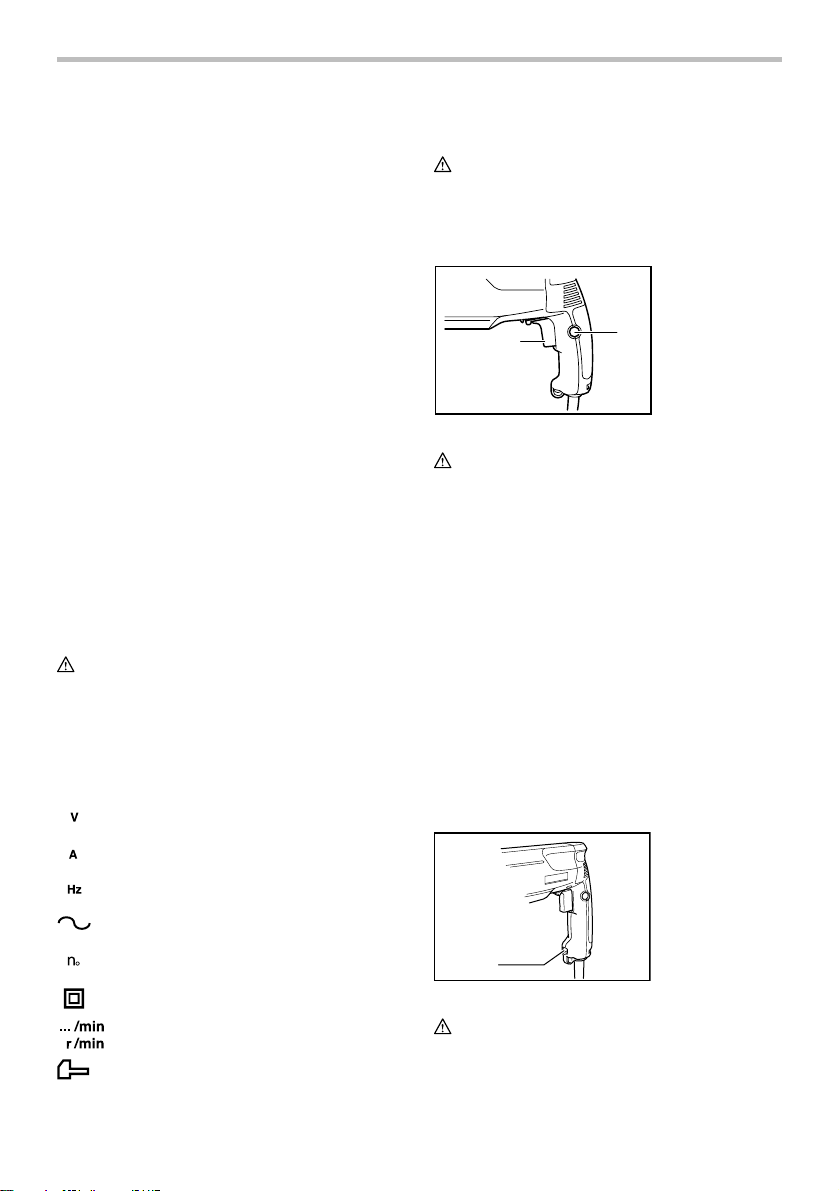
Switch action
1. Switch trigger
2. Lock button
1
001292
CAUTION:
• Before plugging in the tool, always check to see
that the switch trigger actuates properly and
returns to the "OFF" position when released.
For model HR2450F/HR2450/HR2451
To start the tool, simply pull the switch trigger. Tool
speed is increased by increasing pressure on the switch
trigger. Release the switch trigger to stop. For
continuous operation, pull the switch trigger and then
push in the lock button. To stop the tool from the locked
position, pull the switch trigger fully, then release it.
For model HR2452
To start the tool, simply pull the switch trigger. Release
the switch trigger to stop.
For continuous operation, pull the switch trigger and
then push in the lock button.
To stop the tool from the locked position, pull the switch
trigger fully, then release it.
Lighting up the lamps
For model HR2450F only
1
003572
CAUTION:
• Do not look in the light or see the source of light
directly.
2
1. Lamp
4
To turn on the lamp, pull the trigger. Release the trigger
to turn it off.
NOTE:
• Use a dry cloth to wipe the dirt off the lens of lamp.
Be careful not to scratch the lens of lamp, or it may
lower the illumination.
Reversing switch action
For Model HR2450F, HR2450 only
1. Switch trigger
A
B
2
001293
CAUTION:
• Always check the direction of rotation before
operation.
• Use the reversing switch only after the tool comes
to a complete stop. Changing the direction of
rotation before the tool stops may damage the tool.
• When you operate the tool in counterclockwise
rotation, the switch trigger is pulled only halfway
and the tool runs at half speed. For
counterclockwise rotation, you cannot push in the
lock button.
This tool has a reversing switch to change the direction
of rotation. Move the reversing switch lever to the
position (A side) for clockwise rotation or to the
position (B side) for counterclockwise rotation.
Selecting action mode
CAUTION:
• Do not rotate the action mode changing knob when
the tool is running under load. The tool will be
damaged.
• To avoid rapid wear on the mode change
mechanism, be sure that the action mode
changing knob is always positively located in one
of the three action mode positions.
2. Reversing
switch lever
1
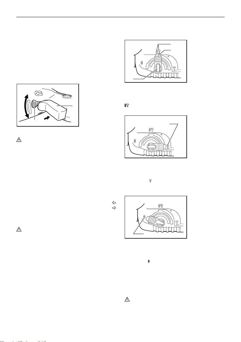
Rotation with hammering
1
2
3
003573
1. Rotation with
hammering
2. Lock button
3. Action mode
changing knob
For drilling in concrete, masonry, etc., depress the lock
button and rotate the action mode changing knob to the
symbol. Use a tungsten-carbide tipped bit.
Hammering only
1. Hammering only
1
003574
For chipping, scaling or demolition operations, depress
the lock button and rotate the action mode changing
knob to the
symbol. Use a bull point, cold chisel,
scaling chisel, etc.
Rotation only
1. Rotation only
1
003575
For drilling in wood, metal or plastic materials, depress
the lock button and rotate the action mode changing
knob to the
symbol. Use a twist drill bit or wood bit.
Torque limiter
The torque limiter will actuate when a certain torque
level is reached. The motor will disengage from the
output shaft.
When this happens, the bit will stop turning.
CAUTION:
• As soon as the torque limiter actuates, switch off
the tool immediately. This will help prevent
5
premature wear of the tool.
• Hole saws cannot be used with this tool. They tend
to pinch or catch easily in the hole. This will cause
the torque limiter to actuate too frequently.
ASSEMBLY
CAUTION:
• Always be sure that the tool is switched off and
unplugged before carrying out any work on the
tool.
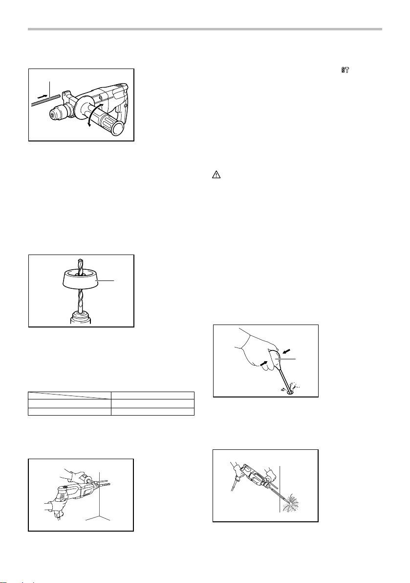
Side handle (auxiliary handle)
1
2
36
5
4
1. Grip base
2. Side grip
3. Loosen
4. Teeth
5. Protrusion
6. Tighten
1. Bit
2. Chuck cover
1
2
001297
To remove the bit, pull the chuck cover down all the way
and pull the bit out.
1
1. Bit
2. Chuck cover
2
001295
Always use the side grip to ensure operating safety.
Install the side grip so that the teeth on the grip fit in
between the protrusions on the tool barrel. Then tighten
the grip by turning clockwise at the desired position. It
may be swung 360° so as to be secured at any position.
Bit grease
Coat the bit shank head beforehand with a small amount
of bit grease (about 0.5 -1 g; 0.02 - 0.04 oz.). This chuck
lubrication assures smooth action and longer service
life.
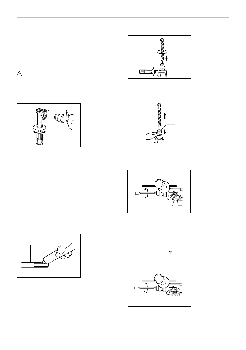
Installing or removing the bit
Clean the bit shank and apply bit grease before installing
the bit.
1. Bit shank
1
2
001296
Insert the bit into the tool. Turn the bit and push it in until
it engages.
After installing, always make sure that the bit is securely
held in place by trying to pull it out.
2. Bit grease
001298
Bit angle (when chipping, scaling or
demolishing)
1. Lock button
2. Action mode
changing knob
12
003576
The bit can be secured at the desired angle. To change
the bit angle, depress the lock button and rotate the
action mode changing knob to the O symbol. Turn the bit
to the desired angle.
Depress the lock button and rotate the action mode
changing knob to the
the bit is securely held in place by turning it slightly.
003577
symbol. Then make sure that
6
Depth gauge
1
001299
The depth gauge is convenient for drilling holes of
uniform depth. Loosen the side grip and insert the depth
gauge into the hole in the side grip. Adjust the depth
gauge to the desired depth and tighten the side grip.
NOTE:
• The depth gauge cannot be used at the position
where the depth gauge strikes against the gear
housing.
1. Depth gauge
Dust cup
1. Dust cup
1
001300
Use the dust cup to prevent dust from falling over the
tool and on yourself when performing overhead drilling
operations. Attach the dust cup to the bit as shown in the
figure. The size of bits which the dust cup can be
attached to is as follows.
Dust cup 5 6 mm - 14.5 mm
Dust cup 9 12 mm - 16 mm
006382
Bit diameter
OPERATION
Hammer drilling operation
Set the action mode changing knob to the
Position the bit at the desired location for the hole, then
pull the switch trigger.
Do not force the tool. Light pressure gives best results.
Keep the tool in position and prevent it from slipping
away from the hole.
Do not apply more pressure when the hole becomes
clogged with chips or particles. Instead, run the tool at
an idle, then remove the bit partially from the hole. By
repeating this several times, the hole will be cleaned out
and normal drilling may be resumed.
CAUTION:
• There is tremendous and sudden twisting force
exerted on the tool/bit at the time of hole
break-through, when the hole becomes clogged
with chips and particles, or when striking
reinforcing rods embedded in the concrete. Always
use the side grip (auxiliary handle) and firmly hold
the tool by both side grip and switch handle during
operations. Failure to do so may result in the loss
of control of the tool and potentially severe injury.
NOTE:
• Eccentricity in the bit rotation may occur while
operating the tool with no load. The tool
automatically centers itself during operation. This
does not affect the driling precision.
Blow-out bulb (optional accessory)
1. Blow-out bulb
1
002449
After drilling the hole, use the blow-out bulb to clean the
dust out of the hole.
Chipping/Scaling/Demolition
symbol.
003579
7
003580
Set the action mode changing knob to the
symbol.
Hold the tool firmly with both hands. Turn the tool on and
apply slight pressure on the tool so that the tool will not
bounce around, uncontrolled. Pressing very hard on the
tool will not increase the efficiency.
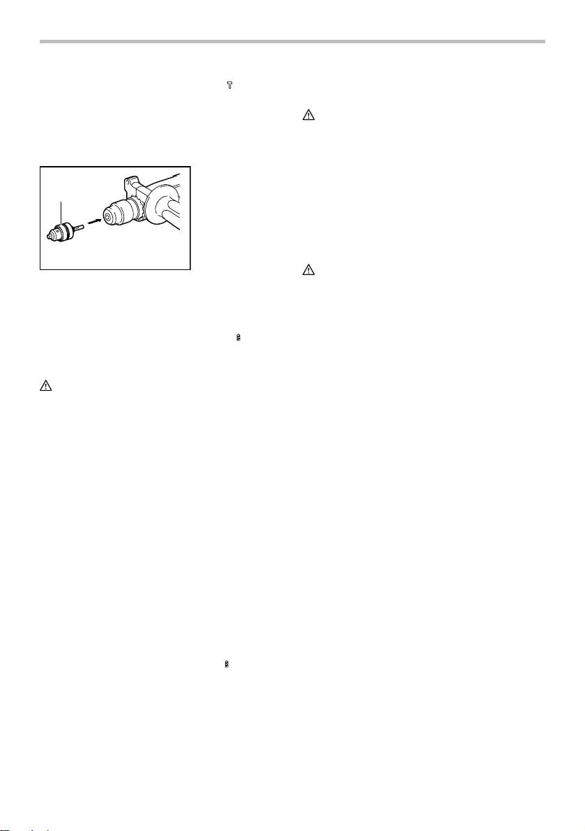
Drilling in wood or metal
1. Drill chuck
assembly
1
001303
Use the optional drill chuck assembly. When installing it,
refer to "Installing or removing the bit" described on the
previous page.
Set the action mode changing knob to the
symbol.
You can drill up to 13 mm(1/2") diameter in metal and up
to 32 mm(1-1/4") diameter in wood.
CAUTION:
• Never use "rotation with hammering" when the drill
chuck assembly is installed on the tool. The drill
chuck assembly may be damaged.
Also, the drill chuck will come off when reversing
the tool.
• Pressing excessively on the tool will not speed up
the drilling. In fact, this excessive pressure will only
serve to damage the tip of your bit, decrease the
tool performance and shorten the service life of the
tool.
• There is a tremendous twisting force exerted on
the tool/bit at the time of hole breakthrough. Hold
the tool firmly and exert care when the bit begins to
break through the workpiece.
• A stuck bit can be removed simply by setting the
reversing switch to reverse rotation in order to back
out. However, the tool may back out abruptly if you
do not hold it firmly.
• Always secure small workpieces in a vise or similar
hold-down device.
• When performing diamond core drilling operations,
always set the change lever to the
position to
use "rotation only" action. If performing diamond
core drilling operations using "rotation with
hammering" action, the diamond core bit may be
damaged.
MAINTENANCE
CAUTION:
• Always be sure that the tool is switched off and
unplugged before attempting to perform inspection
or maintenance.
To maintain product SAFETY and RELIABILITY, repairs,
carbon brush inspection and replacement, any other
maintenance or adjustment should be performed by
Makita Authorized or Factory Service Centers, always
using Makita replacement parts.
ACCESSORIES
CAUTION:
• These accessories or attachments are
recommended for use with your Makita tool
specified in this manual. The use of any other
accessories or attachments might present a risk of
injury to persons. Only use accessory or
attachment for its stated purpose.
If you need any assistance for more details regarding
these accessories, ask your local Makita Service Center.
• SDS-Plus Carbide-tipped bits
• Bull point
• Cold chisel
• Drill chuck assembly
• Drill chuck S13
• Chuck adapter
• Chuck key S13
• Bit grease
• Depth gauge
• Blow-out bulb
• Dust cup
• Dust extractor attachment
• Safety goggles
• Plastic carrying case
• Scaling chisel
• Grooving chisel
• Core bit
• Side grip
• Keyless drill chuck
8

MAKITA LIMITED ONE YEAR WARRANTY
Warranty Policy
Every Makita tool is thoroughly inspected and tested
before leaving the factory. It is warranted to be free of
defects from workmanship and materials for the period
of ONE YEAR from the date of original purchase.
Should any trouble develop during this one year period,
return the COMPLETE tool, freight prepaid, to one of
Makita’s Factory or Authorized Service Centers. If
inspection shows the trouble is caused by defective
workmanship or material, Makita will repair (or at our
option, replace) without charge.
This Warranty does not apply where:
repairs have been made or attempted by others:
repairs are required because of normal wear and
tear:
the tool has been abused, misused or improperly
maintained:
alterations have been made to the tool.
IN NO EVENT SHALL MAKITA BE LIABLE FOR ANY
INDIRECT, INCIDENTAL OR CONSEQUENTIAL
DAMAGES FROM THE SALE OR USE OF THE
PRODUCT. THIS DISCLAIMER APPLIES BOTH
DURING AND AFTER THE TERM OF THIS
WARRANTY.
MAKITA DISCLAIMS LIABILITY FOR ANY IMPLIED
WARRANTIES, INCLUDING IMPLIED WARRANTIES
OF "MERCHANTABILITY" AND "FITNESS FOR A
SPECIFIC PURPOSE," AFTER THE ONE YEAR TERM
OF THIS WARRANTY.
This Warranty gives you specific legal rights, and you
may also have other rights which vary from state to
state. Some states do not allow the exclusion or
limitation of incidental or consequential damages, so
the above limitation or exclusion may not apply to you.
Some states do not allow limitation on how long an
implied warranty lasts, so the above limitation may not
apply to you.
EN0006-1
9
 Loading...