

Page 1
HR2440
HR2440X
HR2440F
HR2441
HR2442
Rotary Hammer
Instruction Manual
B
ohrhammer
Betriebsanleitung
Młot obrotowy
Instrukcja obsługi
Бурильный молоток
для вращательного бурения
Инструкция по эксплуатации
Page 2
1
3
2
5
4
6
7
8
12
9
10
9
10
34
11
12
13
14
56
A
B
15
13
12
16
78
2
Page 3
18
17
910
21
19
20
11 12
23
24
22
3
Page 4
Symbols
The followings show the symbols used for the tool. Be sure that you understand their meaning before use.
Symbole
Die folgenden Symbole werden für die Maschine verwendet. Machen Sie sich vor der Benutzung unbedingt mit ihrer
Bedeutung vertraut.
Symbole
Poniższe symbole używane są do opisu urządzenia. Przed użyciem należy upewnić się, że rozumie się ich znaczenie.
Символы
Следующие объяснения показывают символы, используемые для инструмента. Убедитесь перед
использованием, что Вы понимаете их значение.
❏ Read instruction manual.
❏ Bitte Bedienungsanleitung lesen.
❏ Przeczytaj instrukcję obsługi.
❏ Прочитайте инструкцию по эксплуатации.
❏ DOUBLE INSULATION
❏ DOPPELT SCHUTZISOLIERT
❏ PODWÓJNA IZOLACJA
❏ ДВОЙНАЯ ИЗОЛЯЦИЯ
❏ Only for EU countries
Do not dispose of electric equipment together with household waste material!
In observance of European Directive 2002/96/EC on waste electrical and electronic equipment and
its implementation in accordance with national law, electric equipment that have reached the end of
their life must be collected separately and returned to an environmentally compatible recycling facility.
❏ Nur für EU-Länder
Werfen Sie Elektrowerkzeuge nicht in den Hausmüll!
Gemäß Europäischer Richtlinie 2002/96/EG über Elektro- und Elektronik-Altgeräte und Umsetzung in
nationales Recht müssen verbrauchte Elektrowerkzeuge getrennt gesammelt und einer umweltgerechten Wiederverwertung zugeführt werden.
❏ Dotyczy tylko państw UE
Nie wyrzucaj urządzeń elektrycznych wraz z odpadami z gospodarstwa domowego!
Zgodnie z Europejską Dyrektywą 2002/96/WE w sprawie zużytego sprzętu elektrotechnicznego i
elektronicznego oraz dostosowaniem jej do prawa krajowego, zużyte urządzenia elektryczne należy
posegregować i zutylizować w sposób przyjazny dla środowiska.
❏ Только для стран ЕС
Не выкидывайте электрическое оборудование вместе с бытовым мусором!
В соответствии с европейской директивой 2002/96/EC об утилизацияи старого
электрического и электронного оборудования и её применения в соответствии с местными
законами электрическое оборудование, бывшее в эксплуатации, должно утилизовываться
отдельно безопасным для окружающей среды способом.
4
Page 5

ENGLISH
Explanation of general view
1 Grip base
2 Side grip (auxiliary handle)
3 Teeth
4 Protrusions
5 Loosen
6Tighten
7 Bit shank
8Bit grease
9Bit
SPECIFICATIONS
Model HR2440/HR2440X/HR2440F HR2441 HR2442
Capacities
Concrete
Tungsten-carbide tipped bit................ 24mm 24mm 24mm
Core bit .............................................. 54mm 54mm 54mm
Diamond core bit (dry type) ............... 65mm 65mm 65 mm
Wood .................................................... 32 mm 32 mm 32 mm
Steel ..................................................... 13 mm 13 mm 13 mm
No load speed (min
Blows per minute ..................................... 0– 4,500 0– 4,500 4,500
Overall length .......................................... 352mm 352 mm 352 mm
Net weight................................................ 2.3 kg 2.3 kg 2.3 kg
-1
).............................. 0– 1,100 0 – 1,100 1,100
10 Chuck cover
11 Depth gauge
12 Switch trigger
13 Lock button
14 Lamp (HR2440F only)
15 Reversing switch lever
16 Action mode changing knob
17 Blow-out bulb
18 Dust cup
19 Chuck adapter
20 Keyless drill chuck
21 Sleeve
22 Ring
23 Tighten
24 Loosen
• Due to our continuing program of research and development, the specifications herein are subject to change
without notice.
• Note: Specifications may differ from country to country.
Intended use
The tool is intended for hammer drilling and drilling in
brick, conorete and stone. It is also suitable for drilling
without impact in wood, metal, ceramic and plastic.
Powe r supply
The tool should be connected only to a power supply of
the same voltage as indicated on the nameplate, and can
only be operated on single-phase AC supply. They are
double-insulated in accordance with European Standard
and can, therefore, also be used from sockets without
earth wire.
GENERAL SAFETY RULES
WARNING! Read all instructions. Failure to follow all
instructions listed below may result in electric shock, fire
and/or serious injury. The term “power tool” in all of the
warnings listed below refers to your mains-operated
(corded) power tool or battery-operated (cordless) power
tool.
GEA001-3
SAVE THESE INSTRUCTIONS.
Work area safety
1. Keep work area clean and well lit. Cluttered and
dark areas invite accidents.
2. Do not operate power tools in explosive atmo-
spheres, such as in the presence of flammable
liquids, gases or dust. Power tools create sparks
which may ignite the dust or fumes.
3. Keep children and bystanders away while oper-
ating a power tool. Distractions can cause you to
lose control.
Electrical safety
4. Power tool plugs must match the outlet. Never
modify the plug in any way. Do not use any
adapter plugs with earthed (grounded) power
tools. Unmodified plugs and matching outlets will
reduce risk of electric shock.
5. Avoid body contact with earthed or grounded
surfaces such as pipes, radiators, ranges and
refrigerators. There is an increased risk of electric
shock if your body is earthed or grounded.
6. Do not expose power tools to rain or wet conditions. Water entering a power tool will increase the
risk of electric shock.
7. Do not abuse the cord. Never use the cord for
carrying, pulling or unplugging the power tool.
Keep cord away from heat, oil, sharp edges or
moving parts. Damaged or entangled cords
increase the risk of electric shock.
8. When operating a power tool outdoors, use an
extension cord suitable for outdoor use. Use of a
cord suitable for outdoor use reduces the risk of
electric shock.
Personal safety
9. Stay alert, watch what you are doing and use
common sense when operating a power tool. Do
not use a power tool while you are tired or under
the influence of drugs, alcohol or medication. A
moment of inattention while operating power tools
may result in serious personal injury.
10. Use safety equipment. Always wear eye protection. Safety equipment such as dust mask, non-skid
safety shoes, hard hat, or hearing protection used
for appropriate conditions will reduce personal injuries.
5
Page 6

11. Avoid accidental starting. Ensure the switch is in
the off-position before plugging in. Carrying
power tools with your finger on the switch or plugging in power tools that have the switch on invites
accidents.
12. Remove any adjusting key or wrench before
turning the power tool on. A wrench or a key left
attached to a rotating part of the power tool may
result in personal injury.
13. Do not overreach. Keep proper footing and balance at all times. This enables better control of the
power tool in unexpected situations.
14. Dress properly. Do not wear loose clothing or
jewellery. Keep your hair, clothing, and gloves
away from moving parts. Loose clothes, jewellery
or long hair can be caught in moving parts.
15. If devices are provided for the connection of
dust extraction and collection facilities, ensure
these are connected and properly used. Use of
these devices can reduce dust-related hazards.
Power tool use and care
16. Do not force the power tool. Use the correct
power tool for your application. The correct power
tool will do the job better and safer at the rate for
which it was designed.
17. Do not use the power tool if the switch does not
turn it on and off. Any power tool that cannot be
controlled with the switch is dangerous and must be
repaired.
18. Disconnect the plug from the power source and/
or the battery pack from the power tool before
making any adjustments, changing accessories,
or storing power tools. Such preventive safety
measures reduce the risk of starting the power tool
accidentally.
19. Store idle power tools out of the reach of children and do not allow persons unfamiliar with
the power tool or these instructions to operate
the power tool. Power tools are dangerous in the
hands of untrained users.
20. Maintain power tools. Check for misalignment or
binding of moving parts, breakage of parts and
any other condition that may affect the power
tools operation. If damaged, have the power tool
repaired before use. Many accidents are caused by
poorly maintained power tools.
21. Keep cutting tools sharp and clean. Properly
maintained cutting tools with sharp cutting edges
are less likely to bind and are easier to control.
22. Use the power tool, accessories and tool bits
etc. in accordance with these instructions and in
the manner intended for the particular type of
power tool, taking into account the working conditions and the work to be performed. Use of the
power tool for operations different from those
intended could result in a hazardous situation.
Service
23. Have your power tool serviced by a qualified
repair person using only identical replacement
parts. This will ensure that the safety of the power
tool is maintained.
24. Follow instruction for lubricating and changing
accessories.
25. Keep handles dry, clean and free from oil and
grease.
SPECIFIC SAFETY RULES
DO NOT let comfort or familiarity with product
(gained from repeated use) replace strict adherence
to rotary hammer safety rules. If you use this tool
unsafely or incorrectly, you can suffer serious personal injury.
1. Wear ear protectors. Exposure to noise can cause
hearing loss.
2. Use auxiliary handles supplied with the tool.
Loss of control can cause personal injury.
3. Hold power tools by insulated gripping surfaces
when performing an operation where the cutting
tool may contact hidden wiring or its own cord.
Contact with a “live” wire will make exposed metal
parts of the tool “live” and shock the operator.
4. Wear a hard hat (safety helmet), safety glasses
and/or face shield. Ordinary eye or sun glasses
are NOT safety glasses. It is also highly recommended that you wear a dust mask and thickly
padded gloves.
5. Be sure the bit is secured in place before operation.
6. Under normal operation, the tool is designed to
produce vibration. The screws can come loose
easily, causing a breakdown or accident. Check
tightness of screws carefully before operation.
7. In cold weather or when the tool has not been
used for a long time, let the tool warm up for a
while by operating it under no load. This will
loosen up the lubrication. Without proper warmup, hammering operation is difficult.
8. Always be sure you have a firm footing.
Be sure no one is below when using the tool in
high locations.
9. Hold the tool firmly with both hands.
10. Keep hands away from moving parts.
11. Do not leave the tool running. Operate the tool
only when hand-held.
12. Do not point the tool at any one in the area when
operating. The bit could fly out and injure someone seriously.
13. Do not touch the bit or parts close to the bit
immediately after operation; they may be
extremely hot and could burn your skin.
14. Some material contains chemicals which may be
toxic. Take caution to prevent dust inhalation
and skin contact. Follow material supplier safety
data.
GEB007-2
SAVE THESE INSTRUCTIONS.
WARNING:
MISUSE or failure to follow the safety rules stated in
this instruction manual may cause serious personal
injury.
OPERATING INSTRUCTIONS
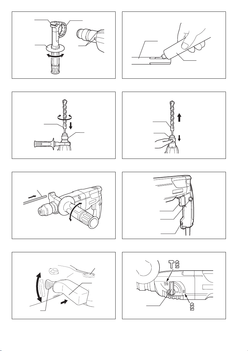
Side grip (auxiliary handle) (Fig. 1)
Always use the side grip to ensure operating safety.
Install the side grip so that the teeth on the grip fit in
between the protrusions on the tool barrel. Then tighten
the grip by turning clockwise at the desired position. It
may be swung 360° so as to be secured at any position.
6
Page 7

Installing or removing the bit
CAUTION:
Always be sure that the tool is switched off and
unplugged before installing or removing the bit.
Clean the bit shank and apply bit grease before installing
the bit. (Fig. 2)
Insert the bit into the tool. Turn the bit and push it in until
it engages. (Fig. 3)
After installing, always make sure that the bit is securely
held in place by trying to pull it out.
To remove the bit, pull the chuck cover down all the way
and pull the bit out. (Fig. 4)
Depth gauge (Fig. 5)
The depth gauge is convenient for drilling holes of uniform depth. Loosen the side grip and insert the depth
gauge into the hole in the side grip. Adjust the depth
gauge to the desired depth and tighten the side grip.
NOTE:
The depth gauge cannot be used at the position where
the depth gauge strikes against the gear housing.
Switch action (Fig. 6)
CAUTION:
Before plugging in the tool, always check to see that the
switch trigger actuates properly and returns to the “OFF”
position when released.
For Model HR2440, HR2440X, HR2440F and HR2441
To start the tool, simply pull the switch trigger. Tool speed
is increased by increasing pressure on the switch trigger.
Release the switch trigger to stop. For continuous operation, pull the switch trigger and then push in the lock button. To stop the tool from the locked position, pull the
switch trigger fully, then release it.
For Model HR2442
To start the tool, simply pull the switch trigger. Release
the switch trigger to stop. For continuous operation, pull
the switch trigger and then push in the lock button. To
stop the tool from the locked position, pull the switch trigger fully, then release it.
Lighting up the lamps (Fig. 6)
For Model HR2440F
CAUTION:
Do not look in the light or see the source of light directly.
To turn on the lamp, pull the trigger. Release the trigger
to turn it off.
NOTE:
Use a dry cloth to wipe the dir t off the lens of lamp. Be
careful not to scratch the lens of lamp, or it may lower the
illumination.
Reversing switch action (Fig. 7)
For Model HR2440, HR2440X, HR2440F
This tool has a reversing switch to change the direction of
rotation. Move the reversing switch lever to the
tion (A side) for clockwise rotation or to the
(B side) for counterclockwise rotation.
CAUTION:
• Always check the direction of rotation before operation.
• Use the reversing switch only after the tool comes to a
complete stop. Changing the direction of rotation
before the tool stops may damage the tool.
posi-
D
E position
• When you operate the tool in counterclockwise rotation,
the switch trigger is pulled only halfway and the tool
runs at half speed. For counterclockwise rotation, you
cannot push in the lock button.
Selection action mode (Fig. 8)
This tool employs an action mode changing knob. Select
one of the two modes suitable for your work needs by
using this knob. For rotation only, turn the knob so that
the arrow on the knob points toward the
the tool body. For rotation with hammering, turn the knob
so that the arrow on the knob points toward the
bol on the tool body.
CAUTION:
• Always set the knob fully to your desired mode symbol.
If you operate the tool with the knob positioned halfway between the mode symbols, the tool may be damaged.
• Use the knob after the tool comes to a complete stop.
M
symbol on
r sym-
Torque limiter
The torque limiter will actuate when a certain torque level
is reached. The motor will disengage from the output
shaft. When this happens, the bit will stop turning.
CAUTION:
• As soon as the torque limiter actuates, switch off the
tool immediately. This will help prevent premature wear
of the tool.
• Hole saws cannot be used with this tool. They tend to
pinch or catch easily in the hole. This will cause the
torque limiter to actuate too frequently.
Hammer drilling operation
Position the bit at the desired location for the hole, then
pull the trigger.
Do not force the tool. Light pressure gives best results.
Keep the tool in position and prevent it from slipping away
from the hole.
Do not apply more pressure when the hole becomes
clogged with chips or particles. Instead, run the tool at an
idle, then remove the bit partially from the hole. By
repeating this several times, the hole will be cleaned out
and normal dr illing may be resumed.
CAUTION:
There is tremendous and sudden twisting force exerted
on the tool/bit at the time of hole breakthrough, when the
hole becomes clogged with chips and par ticles, or when
striking reinforcing rods embedded in the concrete.
Always use the side grip (auxiliary handle) and firmly
hold the tool by both side grip and switch handle during
operations. Failure to do so may result in the loss of control of the tool and potentially severe injury.
NOTE:
Eccentricity in the bit rotation may occur while operating
the tool with no load. The tool automatically centers itself
during operation. This does not affect the drilling precision.
Bit grease
Coat the bit shank head beforehand with a small amount
of bit grease (about 0.5 – 1 g).
This chuck lubrication assures smooth action and longer
service life.
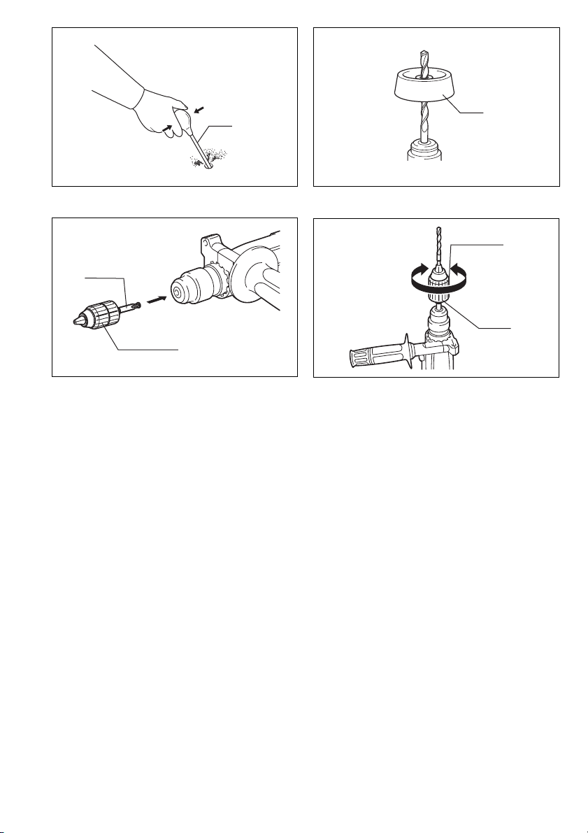
Blow-out bulb (Fig. 9)
Use the blow-out bulb to clean out the hold.
7
Page 8
Dust cup (Fig. 10)
Use the dust cup to prevent dust from falling over the tool
and on yourself when performing overhead drilling operations. Attach the dust cup to the bit as shown in Fig. 10.
The size of bits which the dust cup can be attached to is
as follows.
Bit diameter (mm)
Dust cup 5 6 – 14.5
Dust cup 9 12 – 16
Drilling in wood or metal (Fig. 11 and 12)
Use the optional drill chuck assembly (standard equipment for Model HR2440X). When installing it, refer to
“Installing or removing drill bit” described on the previous
page.
Hold the ring and turn the sleeve counterclockwise to
open the chuck jaws. Place the bit in the chuck as far as
it will go. Hold the ring firmly and turn the sleeve clockwise to tighten the chuck.
To remove the bit, hold the ring and turn the sleeve counterclockwise. Set the action mode changing knob to
“rotation only”. You can drill up to 13 mm diameter in
metal and up to 32 mm diameter in wood.
CAUTION:
• Never use “rotation with hammering” when the drill
chuck assembly is installed on the tool. The drill chuck
assembly may be damaged.
Also, the drill chuck will come off when reversing the
tool. (For Model HR2440, HR2440X, HR2440F)
• Pressing excessively on the tool will not speed up the
drilling. In fact, this excessive pressure will only serve
to damage the tip of your bit, decrease the tool performance and shorten the service life of the tool.
• There is a tremendous twisting force exerted on the
tool/bit at the time of hole breakthrough. Hold the tool
firmly and exert care when the bit begins to break
through the workpiece.
• A stuck bit can be removed simply by setting the
reversing switch to reverse rotation in order to back out.
However, the tool may back out abruptly if you do not
hold it firmly.
• Always secure small workpieces in a vise or similar
hold-down device.
• When performing diamond core drilling operation,
always set the change lever to the
rotation only” action. If performing diamond core
“
drilling operation with
action, the diamond core bit may be damaged.
rotation with hammering
“
position to use
M
MAINTENANCE
CAUTION:
Always be sure that the tool is switched off and
unplugged before carrying out any work on the tool.
To maintain product safety and reliability, repairs, maintenance or adjustment should be carried out by a Makita
Authorized Service Center.
For European countries only
Noise and Vibration
The typical A-weighted noise levels are
sound pressure level:89 dB (A)
sound power level: 100 dB (A)
Uncertainty is 3 dB (A).
The typical weighted root mean square acceleration
value is 9 m/s
These values have been obtained according to
EN60745.
We declare under our sole responsibility that this product
is in compliance with the following standards of standardized documents,
in accordance with Council Directives, 89/336/EEC and
98/37/EC.
– Wear ear protection. –
2
.
EC-DECLARATION OF CONFORMITY
EN60745, EN55014, EN61000
Yasuhiko Kanzaki
Director
CE 2005
MAKITA INTERNATIONAL EUROPE LTD.
Michigan Drive, Tongwell, Milton Keynes,
Bucks MK15 8JD, ENGLAND
Responsible manufacturer:
Makita Corporation Anjo Aichi Japan
”
ENG006-2-V4
ENH101-5
8
Page 9

DEUTSCH
Übersicht
1 Griffbasis
2 Zusatzhandgriff (Seitengriff)
3 Innenverzahnung
4Außenverzahnung
5Lösen
6 Festziehen
7 Einsteckende
8 Bohrer/-Meißelfett
TECHNISCHE DATEN
Modell HR2440/HR2440X/HR2440F HR2441 HR2442
Bohrleistung
Beton
HM-bestückter Bohrer ...................... 24 mm 24mm 24mm
Bohrkrone......................................... 54mm 54 mm 54 mm
Diamantkernbohrer (Trockentyp)...... 65 mm 65 mm 65mm
Holz ...................................................... 32 mm 32 mm 32 mm
Stahl ..................................................... 13 mm 13 mm 13 mm
Leerlaufdrehzahl (min
Schlagzahl ............................................... 0– 4 500 0 – 4500 4500
Gesamtlänge ........................................... 352 mm 352 mm 352 mm
Nettogewicht............................................ 2,3 kg 2,3 kg 2,3 kg
-1
).......................... 0– 1 100 0 – 1100 1100
9 SDS-Plus-Bohrer
10 Werkzeugverriegelung
11 Tiefenanschlag
12 Elektronikschalter
13 Schalterarretierung
14 Lampe (nur für HR2440F)
15 Drehrichtungsumschalter
16 Betriebsartenschalter
17 Ausbläser
18 Staubschutzkappe
19 Bohrfutteradapter
20 Schlüsselloses Bohrfutter
21 Werkzeugverriegelung
22 Klemmring
23 Festziehen
24 Lösen
• Wir behalten uns vor, Änderungen im Zuge der Ent-
wicklung und des technischen Fortschritts ohne vorherige Ankündigung vorzunehmen.
• Hinweis: Die technischen Daten können von Land zu
Land abweichen.
Vorgesehene Verwendung
Das Werkzeug ist für Schlagbohren und Bohren in Ziegel, Beton und Stein vorgesehen. Es eignet sich auch für
normales Bohren in Holz, Metall, Keramik und Kunststoff.
Netzanschluß
Die Maschine darf nur an die auf dem Typenschild angegebene Netzspannung angeschlossen werden und
arbeitet nur mit Einphasen- Wechselspannung. Sie ist
entsprechend den Europäischen Richtlinien doppelt
schutzisoliert und kann daher auch an Steckdosen ohne
Erdanschluß betrieben werden.
ALLGEMEINE SICHERHEITSREGELN
WARNUNG! Alle Anweisungen durchlesen. Eine
Missachtung der unten aufgeführten Anweisungen kann
zu einem elektrischen Schlag, Brand und/oder schweren
Verletzungen führen. Der Ausdruck “Elektrowerkzeug” in
allen nachstehenden Warnhinweisen bezieht sich auf Ihr
mit Netzstrom (mit Kabel) oder Akku (ohne Kabel) betriebenes Elektrowerkzeug.
DIESE ANWEISUNGEN AUFBEWAHREN.
Sicherheit im Arbeitsbereich
1. Halten Sie den Arbeitsbereich sauber und gut
beleuchtet. Unaufgeräumte und dunkle Bereiche
führen zu Unfällen.
2. Betreiben Sie Elektrowerkzeuge nicht in explosi-
ven Umgebungen, wie z.B. in Gegenwart von
brennbaren Flüssigkeiten, Gasen oder Staub.
Elektrowerkzeuge erzeugen Funken, die den Staub
oder die Dämpfe entzünden können.
3. Halten Sie Kinder und Umstehende während der
Benutzung eines Elektrowerkzeugs vom Arbeitsbereich fern. Ablenkungen können dazu führen,
dass Sie die Kontrolle verlieren.
Elektrische Sicherheit
4. Der Stecker des Elektrowerkzeugs muss an die
Steckdose angepasst sein. Der Stecker darf auf
keinen Fall in irgendeiner Form abgeändert werden. Verwenden Sie keine Adapterstecker mit
geerdeten Elektrowerkzeugen. Vorschriftsmäßige
Stecker und passende Steckdosen reduzieren die
Stromschlaggefahr.
5. Vermeiden Sie Körperkontakt mit geerdeten
Gegenständen (z.B. Rohre, Kühler, Herde, Kühlschränke). Es besteht erhöhte Stromschlaggefahr,
falls Ihr Körper Erdkontakt hat.
6. Setzen Sie Elektrowerkzeuge keinem Regen
oder Nässe aus. Wasser, das in ein Elektrowerk-
zeug eindringt, erhöht die Stromschlaggefahr.
7. Behandeln Sie das Kabel sorgfältig. Benutzen
Sie das Kabel niemals zum Tragen, Ziehen oder
Abtrennen des Elektrowerkzeugs. Halten Sie das
Kabel von Hitze, Öl, scharfen Kanten oder
beweglichen Teilen fern. Ein beschädigtes oder
verheddertes Kabel erhöht die Stromschlaggefahr.
8. Wenn Sie ein Elektrowerkzeug im Freien betreiben, verwenden Sie ein für Freiluftbenutzung
geeignetes Verlängerungskabel. Die Verwendung
eines für Freiluftbenutzung geeigneten Kabels reduziert die Stromschlaggefahr.
9
Page 10

Persönliche Sicherheit
9. Bleiben Sie wachsam, und lassen Sie beim
Umgang mit einem Elektrowerkzeug Vorsicht
und gesunden Menschenverstand walten. Benutzen Sie keine Elektrowerkzeuge, wenn Sie müde
sind oder unter dem Einfluss von Drogen, Alkohol oder Medikamenten stehen. Ein Augenblick
der Unachtsamkeit während der Benutzung von
Elektrowerkzeugen kann zu schweren Verletzungen
führen.
10. Benutzen Sie Schutzausrüstung. Tragen Sie
stets eine Schutzbrille. Sachgemäßer Gebrauch
von Schutzausrüstung (z.B. Staubmaske, rutschfeste Sicherheitsschuhe, Helm und Gehörschutz) trägt
zu einer Reduzierung der Verletzungsgefahr bei.
11. Vermeiden Sie unbeabsichtigtes Einschalten.
Vergewissern Sie sich, dass der Schalter in der
Aus-Stellung ist, bevor Sie den Netzstecker einstecken. Das Tragen von Elektrowerkzeugen mit
dem Finger am Ein-Aus-Schalter oder das Anschließen bei eingeschaltetem Ein-Aus-Schalter führt zu
Unfällen.
12. Etwaige Einstell- oder Schraubenschlüssel sind
vor dem Einschalten des Elektrowerkzeugs zu
entfernen. Ein Schrauben- oder Einstellschlüssel,
der auf einem rotierenden Teil des Elektrowerkzeugs
stecken gelassen wird, kann zu einer Verletzung
führen.
13. Übernehmen Sie sich nicht. Achten Sie stets auf
sicheren Stand und gute Balance. Sie haben
dann in unerwarteten Situationen eine bessere Kontrolle über das Elektrowerkzeug.
14. Achten Sie auf zweckmäßige Kleidung. Tragen
Sie keine lose Kleidung oder Schmuck. Halten
Sie Haare, Kleidung und Handschuhe von
beweglichen Teilen fern. Lose Kleidung, Schmuck
oder langes Haar kann sich in beweglichen Teilen
verfangen.
15. Wenn Anschlussvorrichtungen für Staubabsaug- und Staubsammelgeräte vorhanden sind,
sollten diese montiert und sachgerecht verwendet werden. Die Verwendung solcher Vorrichtungen
kann durch Staub verursachte Gefahren reduzieren.
Gebrauch und Pflege von Elektrowerkzeugen
16. Setzen Sie Elektrowerkzeuge keiner Gewaltanwendung aus. Verwenden Sie das korrekte Elektrowerkzeug für Ihre Anwendung. Ein korrektes
Elektrowerkzeug verrichtet die anstehende Arbeit
bei sachgemäßer Handhabung besser und sicherer.
17. Benutzen Sie das Elektrowerkzeug nicht, wenn
es sich nicht mit dem Ein-Aus-Schalter ein- und
ausschalten lässt. Ein Elektrowerkzeug, das nicht
auf die Schalterbetätigung reagiert, ist gefährlich
und muss repariert werden.
18. Trennen Sie den Stecker von der Stromquelle
und/oder den Akku vom Elektrowerkzeug, bevor
Sie Einstellungen durchführen, Zubehör auswechseln oder das Elektrowerkzeug lagern. Sol-
che vorbeugenden Sicherheitsmaßnahmen
reduzieren die Gefahr eines versehentlichen Einschaltens des Elektrowerkzeugs.
19. Bewahren Sie unbenutzte Elektrowerkzeuge
außer Reichweite von Kindern auf, und lassen
Sie nicht zu, dass Personen, die nicht mit dem
Elektrowerkzeug oder diesen Anweisungen vertraut sind, das Elektrowerkzeug benutzen. Elek-
trowerkzeuge in den Händen unerfahrener Benutzer
sind gefährlich.
20. Pflegen Sie Elektrowerkzeuge. Überprüfen Sie
Elektrowerkzeuge auf Fehlausrichtung oder
Schleifen beweglicher Teile, Beschädigung von
Teilen und andere Zustände, die ihren Betrieb
beeinträchtigen können. Lassen Sie das Elektrowerkzeug bei Beschädigung vor der Benutzung
reparieren. Viele Unfälle werden durch schlecht
gewartete Elektrowerkzeuge verursacht.
21. Halten Sie Schneidwerkzeuge scharf und sauber. Gut instand gehaltene Schneidwerkzeuge mit
scharfen Schneiden sind weniger anfällig für Klemmen und lassen sich leichter handhaben.
22. Benutzen Sie das Elektrowerkzeug, das Zubehör,
die Einsatzwerkzeuge usw. gemäß diesen
Anweisungen und in der für das jeweilige Elektrowerkzeug vorgesehenen Weise, und berücksichtigen Sie stets die Arbeitsbedingungen und
die anstehende Arbeit. Unsachgemäßer Gebrauch
des Elektrowerkzeugs kann zu einer Gefahrensituation führen.
Wartung
23. Lassen Sie Ihr Elektrowerkzeug nur unter Verwendung identischer Ersatzteile von einem qualifizierten Wartungstechniker warten. Dadurch
wird die Aufrechterhaltung der Sicherheit des Elektrowerkzeugs gewährleistet.
24. Befolgen Sie die Anweisungen für die Schmierung und den Austausch von Zubehör.
25. Halten Sie Griffe trocken, sauber und frei von Öl
und Fett.
SPEZIELLE SICHERHEITSREGELN
Lassen Sie sich NICHT durch Bequemlichkeit oder
Vertrautheit mit dem Produkt (durch wiederholten
Gebrauch erworben) von der strikten Einhaltung der
Sicherheitsregeln für den Bohrhammer abhalten.
Wenn Sie dieses Werkzeug auf unsichere oder
unsachgemäße Weise benutzen, können Sie schwere
Verletzungen erleiden.
1. Tragen Sie Gehörschützer. Lärmeinwirkung kann
zu Gehörverlust führen.
2. Benutzen Sie die mit dem Werkzeug gelieferten
Zusatzgriffe. Verlust der Kontrolle kann Verletzun-
gen verursachen.
3. Halten Sie Elektrowerkzeuge nur an den isolierten Griffflächen, wenn Sie Arbeiten ausführen,
bei denen die Gefahr besteht, dass verborgene
Kabel oder das eigene Kabel kontaktiert werden.
Bei Kontakt mit einem stromführenden Kabel werden die freiliegenden Metallteile des Werkzeugs
ebenfalls stromführend, so dass der Benutzer einen
elektrischen Schlag erleiden kann.
4. Tragen Sie Schutzhelm, Schutzbrille und/oder
Gesichtsschutz. Eine gewöhnliche Brille oder
Sonnenbrille ist KEIN Ersatz für eine Sicherheitsbrille. Das Tragen einer Staubmaske und
dick gepolsterter Handschuhe ist ebenfalls zu
empfehlen.
10
Page 11

5. Vergewissern Sie sich vor der Arbeit, dass der
Einsatz sicher montiert ist.
6. Das Werkzeug ist so ausgelegt, dass es bei normalem Betrieb Vibrationen erzeugt. Durch
Lockerung von Schrauben kann es zu einem Ausfall oder Unfall kommen. Überprüfen Sie sorgfältig die Festigkeit der Schrauben vor der Arbeit.
7. Lassen Sie das Werkzeug bei niedrigen Temperaturen oder nach längerer Nichtbenutzung eine
Zeit lang im Leerlauf warm laufen. Dadurch wird
die Schmierung verbessert. Betrieb im kalten
Zustand erschwert die Schlagbohrarbeit.
8. Achten Sie stets auf sicheren Stand.
Vergewissern Sie sich bei Einsatz des Werk-
zeugs an hochgelegenen Arbeitsplätzen, dass
sich keine Personen darunter aufhalten.
9. Halten Sie das Werkzeug mit beiden Händen
fest.
10. Halten Sie die Hände von beweglichen Teilen
fern.
11. Lassen Sie das Werkzeug nicht unbeaufsichtigt
laufen. Benutzen Sie das Werkzeug nur mit
Handhaltung.
12. Richten Sie das Werkzeug während des Betriebs
nicht auf umstehende Personen. Der Einsatz
könnte herausschnellen und schwere Verletzungen verursachen.
13. Vermeiden Sie eine Berührung des Bohrereinsatzes oder der umliegenden Teile unmittelbar
nach der Bearbeitung, weil die Teile noch sehr
heiß sind und Hautverbrennungen verursachen
können.
14. Manche Materialien können giftige Chemikalien
enthalten. Treffen Sie Vorsichtsmaßnahmen, um
das Einatmen von Arbeitsstaub und Hautkontakt
zu verhüten. Befolgen Sie die Sicherheitsdaten
des Materialherstellers.
BEWAHREN SIE DIESE HINWEISE
SORGFÄLTIG AUF.
WARNUNG:
MISSBRAUCH oder Missachtung der
Sicherheitsvorschriften in dieser Anleitung
können schwere Verletzungen verursachen.
BEDIENUNGSHINWEISE
Seitengriff (Zusatzgriff) (Abb. 1)
Den Griff in der gewünschten Arbeitsposition mit der
Innenverzahnung auf die Außenverzahnung des Maschinengehäuses stecken und durch Rechtsdrehung des
Griffstücks festziehen. Der Zusatzhandgriff kann um
360° geschwenkt und in jeder beliebigen Stellung arretiert werden.
Montage bzw. Demontage von
Einsatzwerkzeugen
VORSICHT:
Vergewissern Sie sich vor der Montage bzw. Demontage
eines Einsatzwerkzeuges grundsätzlich, daß die
Maschine abgeschaltet und der Netzstecker gezogen ist.
Den Bohrerschaft vor der Montage des Bohrers reinigen
und mit dem Bohrer-/Meißelfett schmieren. (Abb. 2)
Einsatzwerkzeug drehend in die Werkzeugaufnahme
einführen und einschieben, bis es einrastet. (Abb. 3)
Prüfen Sie nach jedem Montagevorgang den sicheren
Sitz des Einsatzwerkzeugs durch Zugversuch.
Zur Demontage des Einsatzwerkzeugs die Werkzeugverriegelung bis zum Anschlag in Richtung Maschinengehäuse ziehen und das Einsatzwerkzeug entnehmen.
(Abb. 4)
Bohrtiefenbegrenzung (Abb. 5)
Die Bohrtiefe kann über den Tiefenanschlag eingestellt
werden. Dazu lösen Sie den Zusatzhandgriff und führen
den Tiefenanschlag in die Bohrung des Zusatzhandgriffes ein. Stellen Sie den Tiefenanschlag auf die
gewünschte Bohrtiefe und ziehen anschließend den
Zusatzhandgriff wieder fest.
HINWEIS:
Bei Positionierung des Tiefenanschlags gegen das
Getriebegehäuse kann dieser nicht verwendet werden.
Schalterfunktion (Abb. 6)
VORSICHT:
Vor dem Anschließen der Maschine an das Stromnetz
stets überprüfen, ob der Elektronikschalter ordnungsgemäß funktioniert und beim Loslassen in die AUS- Stellung zurückkehrt.
Für Modell HR2440, HR2440X, HR2440F und HR2441
Die Drehzahl erhöht sich durch verstärkte Druckaus-
übung auf den Elektronikschalter. Zum Einschalten drük-
ken Sie den Elektronikschalter. Zum Ausschalten lassen
Sie den Schalter los. Für Dauerbetrieb drücken Sie den
Elektronikschalter und gleichzeitig die Schalterarretierung. Zum Ausschalten des Dauerbetriebs den Elektronikschalter drücken und wieder loslassen.
Für Modell HR2442
Die Drehzahl erhöht sich durch verstärkte Druckaus-
übung auf den Elektronikschalter. Zum Ausschalten las-
sen Sie den Schalter los. Für Dauerbetrieb drücken Sie
den Elektronikschalter und gleichzeitig die Schalterarretierung. Zum Ausschalten des Dauerbetriebs den Elektronikschalter drücken und wieder loslassen.
Einschalten der Lampen (Abb. 6)
Für Modell HR2440F
VORSICHT:
Blicken Sie nicht direkt in das Licht oder die Lichtquelle.
Betätigen Sie den Ein-Aus-Schalter zum Einschalten der
Lampe. Lassen Sie den Ein-Aus-Schalter zum Ausschalten der Lampe los.
HINWEIS:
Wischen Sie Schmutz auf der Linse der Lampe mit
einem trockenen Tuch ab. Achten Sie sorgfältig darauf,
dass Sie die Linse der Lampe nicht verkratzen, weil sich
sonst die Lichtstärke verringert.
Drehrichtungsumschalter (Abb. 7)
Für Modell HR2440, HR2440X, HR2440F
Diese Maschine besitzt einen Drehrichtungsumschalter.
Stellen Sie den Drehrichtungs-Umschalthebel für
Rechtsdrehung auf die Stellung
Linksdrehung auf die Stellung
VORSICHT:
• Prüfen Sie stets die Drehrichtung, bevor Sie mit dem
Bohren Beginnen.
• Wechseln Sie niemals die Drehrichtung, bevor der
Motor zum Stillstand gekommem ist. Andernfalls kann
die Maschine beschädigt werden.
(Seite A) oder für
D
E (Seite B).
11
Page 12

• Wird das Werkzeug mit Linksdrehung betrieben, lässt
sich der Ein-Aus-Schalter nur halb drücken, und das
Werkzeug läuft nur mit halber Drehzahl. Bei Linksdrehung lässt sich der Arretierknopf nicht hineindrücken.
Wahl der Betriebsart (Abb. 8)
Diese Maschine verfügt über einen Betriebsartenschalter, mit dem die jeweils gewünschte Betriebsart gewählt
werden kann. Zum Drehbohren den Betriebsartenschalter mit dem Pfeil auf das Symbol
häuses drehen. Zum Hammerbohren den
Betriebsartenschalter mit dem Pfeil auf das Symbol
des Maschinengehäuses drehen.
VORSICHT:
• Den Betriebsartenschalter stets bis zum Anschlag auf
das Symbol der gewünschten Betriebsart drehen.
Durch den Betrieb in einer Zwischenstellung des
Schalters kann die Maschine beschädigt werden.
• Betätigen Sie den Knopf erst, nachdem das Werkzeug
völlig zum Stillstand gekommen ist.
des Maschinenge-
M
r
Drehmomentbegrenzung
Die Rutschkupplung der Maschine begrenzt das Drehmoment auf einen werkseitig eingestellten Maximalwert.
Bei Auslösen trennt die Rutschkupplung den Antrieb von
der Bohrspindel und das Einsatzwerkzeug kommt zum
Stillstand.
VORSICHT:
• Bei Auslösen der Rutschkupplung Maschine sofort
abschalten, um frühzeitigen Verschleiß zu vermeiden.
• Lochsägen sind für den Einsatz in dieser Maschine
nicht geeignet, da diese Einsatzwerkzeuge zu hohe
Drehmomente abverlangen.
Betrieb: Hammerbohren
Den Bohrer erst an die gewünschte Position setzen und
den Bohrvorgang dann durch Drücken des Elektronikschalters beginnen.
Das Gerät im rechten Winkel zur Werkstückoberfläche
sicher führen, um ein Abrutschen des Bohrers zu verhindern. Während des Bohrbetriebs nur den erforderlichen
Gegendruck halten, der unmittelbar der Schlagenergie
des Gerätes entgegenwirkt.
Sollte die Bohrmehlabfuhr (z. B. durch feuchtes Gestein)
gestört sein, ziehen Sie den Bohrer aus der Bohrung
heraus und entfernen Sie das Bohrmehl aus der Bohrung bzw. den Spiralnuten des Bohrers.
VORSICHT:
Beim Bohren in eisenbewehrtem Beton kann der Bohrer
blockieren und so die Rutschkupplung der Maschine
auslösen. Achten Sie daher auf sicheren Stand und
benutzen Sie immer den Seitengriff, um die hohen Rück-
drehmomente aufzufangen.
HINWEIS:
Es kann zu einer Rundlaufabweichung in der Bohrerdrehung kommen, wenn das Werkzeug mit Nulllast betrieben wird. Während des Betriebs zentriert sich das
Werkzeug automatisch. Dies hat keinen Einfluss auf die
Bohrgenauigkeit.
Schmierung der Einsatzwerkzeuge
Den Aufnahmeschaft vor dem Einsetzen in das Gerät
säubern und anschließend mit Bohrerfett schmieren
(ca. 0,5 – 1,0 g).
Dies gewährleistet eine einwandfreie Funktion der Werkzeugaufnahme und einen minimalen Verschleiß des Aufnahmeschaftes.
Ausbläser (Abb. 9)
Verwenden Sie den Ausbläser, um das Bohrloch von
Spänen und Partikeln zu säubern.
Staubschutzkappe (Abb. 10)
Bei Überkopfarbeiten die Staubschutzkappe verwenden,
um zu verhindern, daß Staub auf den Bedienenden und
die Werkzeugaufnahme fällt. Die Staubschutzkappe, wie
in Abb. 10 gezeigt, auf dem Bohrer befestigen. Die
Staubschutzkappe kann für folgende Bohrergrößen verwendet werden.
Bohrerdurchmesser
Staubschutzkappe 5 6 – 14,5 mm
Staubschutzkappe 9 12 – 16 mm
Bohren in Holz oder Metall (Abb. 11 und 12)
Verwenden Sie den gesonderten Bohrfuttersatz (Standardausstattung für Modell HR2440X). Nehmen Sie zur
Montage auf den Abschnitt “Montage und Demontage
des Bohrers” auf der vorhergehenden Seite Bezug.
Halten Sie den Klemmring fest und drehen Sie die Werkzeugverriegelung entgegen dem Uhrzeigersinn, um die
Bohrfutterbacken zu öffnen. Führen Sie das Einsatzwerkzeug bis zum Anschlag in das Spannfutter ein. Halten
Sie den Klemmring fest und drehen Sie die Werkzeugverriegelung im Uhrzeigersinn, um das Bohrfutter festzuziehen.
Zum Entfernen des Einsatzwerkzeugs halten Sie den
Klemmring und drehen die Werkzeugverriegelung entgegen dem Uhrzeigersinn. Stellen Sie den Betriebsartenschalter auf die Position “Bohren”. Sie können Löcher
von bis zu 13 mm Durchmesser in Metall und von bis zu
32 mm Durchmesser in Holz bohren.
VORSICHT:
• Bei montiertem Bohrfutteradapter mit dem Bohrfutter
darf keinesfalls die Betriebsart “Schlagbohren” gewählt
werden.
Bohrfutter und Bohrfutteradapter können andernfalls
beschädigt werden bzw. das Bohrfutter kann sich bei
Linkslauf öffnen. (Für Modell HR2440, HR2440X,
HR2440F)
• Ein zu starker Druck auf die Maschine bewirkt keine
Beschleunigung der Bohrleistung. Ein zu hoher
Schnittdruck führt zu einer Beschädigung der Bohrerspitze und damit zu Verringerung der Bohrerstandzeit
und Überanspruchung der Maschine.
• Beim Austritt des Bohrers aus dem Werkstück wirkt ein
hohes Rückdrehmoment auf die Maschine. Deshalb
die Maschine gut festhalten und den Vorschub verringern, wenn der Bohrer durch das Werkstück dringt.
• Ein festsitzender Bohrer läßt sich durch Umschalten
der Drehrichtung auf Linkslauf wieder herausdrehen.
Die Maschine ist gut festzuhalten, da im Linkslauf ein
hohes Rückdrehmoment auf die Maschine auftritt.
• Kleine Werkstücke stets in einem Schraubstock einspannen oder mit einer Schraubzwinge sichern.
• Stellen Sie den Umschalthebel beim Bohren mit Diamantkernbohrer immer auf die Position
Betriebsart “Bohren”. Werden Arbeiten mit dem Diamantkernbohrer in der Betriebsart “Schlagbohren” ausgeführt, kann der Diamantkernbohrer beschädigt
werden.
für die
M
12
Page 13

WARTUNG
VORSICHT:
Vor Arbeiten an der Maschine vergewissern Sie sich, daß
der Schalter in der Position OFF und der Netzstecker
gezogen ist.
Zur Gewährleistung der Produktsicherheit und -zuverläs-
sigkeit sind Reparaturen, Wartungsarbeiten und Einstellungen von einer Makita-Service-Station auszuführen.
Nur für europäische Länder
Geräusch- und Vibrationsentwicklung
ENG006-2-V4
Die typischen A-bewerteten Geräuschpegel betragen:
Schalldruckpegel: 89 dB (A)
Schalleistungspegel: 100 dB (A)
Die Abweichung beträgt 3 dB (A).
Der gewichtete Effektivwert der Beschleunigung beträgt
2
.
9m/s
– Gehörschutz tragen. –
Diese Werte wurden gemäß EN60745 erhalten.
CE-KONFORMITÄTSERKLÄRUNG
ENH101-5
Hiermit erklärt wir unter unserer alleinigen Verantwortung, daß dieses Produkt gemäß den Ratsdirektiven 89/
336/EWG und 98/37/EG mit den folgenden Normen von
Normendokumenten übereinstimmen:
EN60745, EN55014, EN61000.
Yasuhiko Kanzaki
CE 2005
Direktor
MAKITA INTERNATIONAL EUROPE LTD.
Michigan Drive, Tongwell, Milton Keynes,
Bucks MK15 8JD, ENGLAND
Verantwortlicher Hersteller:
Makita Corporation Anjo Aichi Japan
13
Page 14

POLSKI
Wyjaśnienia dotyczące urządzenia i jego użycia
1 Podstawa rączki
2 Rączka boczna
(uchwyt dodatkowy)
3Zęby
4Występy
5 Poluźnij
6 Dociśnij
7 Trzon wiertła
8 Smar do wiertła
9 Wiertło
10 Osłona uchwytu
11 Wskaźnik głębokości
12 Język włącznika
13 Przycisk blokady
14 Lampka (dla modelu HR2440F)
15 Dźwignia zmiany kierunku
16 Dźwignia zmiany trybu pracy
17 Gruszka do wydmuchiwania
pyłów
18 Osłona przed pyłem
19 Adaptor zacisku
20 Zacisk wiertła
nie wymagający klucza
21 Tuleja
22 Pierścień
23 Zakręcanie
24 Odkręcanie
DANE TECHNICZNE
Model HR2440/HR2440X/HR2440F HR2441 HR2442
Wydajność
Beton
Wiertło z wierzchołkiem z węglika wolframu ....... 24 mm 24mm 24 mm
Koronka wiertnicza .............................................. 54 mm 54 mm 54 mm
Diamentowa koronka wiertnicza (typ suchy) ....... 65mm 65mm 65 mm
Drewno................................................................... 32 mm 32 mm 32 mm
Stal......................................................................... 13 mm 13mm 13mm
Prędkość bez obciążenia (min
Uderzenia na minutę ..................................................... 0 – 4.500 0 – 4.500 4.500
Całkowita długość ........................................................ 352 mm 352 mm 352 mm
Ciężar netto .................................................................. 2,3 kg 2,3 kg 2,3 kg
• Ze względu na prowadzony program udoskonaleń i
badań, podane dane techniczne mogą zostać
zmienione bez uprzedzenia.
• Uwaga: Dane techniczne mogą się różnić w zależności
od kraju.
Przeznaczenie
Urządzenie jest przeznaczone do wiercenia udarowego i
wiercenia w cegle, betonie i kamieniu. Nadaje się
również do wiercenia bez uderzeń w drewnie, metalu,
materiałach ceramicznych i plastiku.
Zasilanie
Urządzenie to, powinno być podłączone tylko do źródła
zasilania o takim samym napięciu jak pokazano na
tabliczce znamionowej i może być używane tylko dla
zmiennego prądu jednofazowego. Zgodnie ze
standardami Unii Europejskiej zastosowano podwójną
izolację i dlatego też możliwe jest zasilanie z gniazda bez
uziemienia.
OGÓLNE ZASADY BEZPIECZEŃSTWA
UWAGA! Przeczytaj wszystkie instrukcje.
Niestosowanie się do wszystkich instrukcji podanych
poniżej może doprowadzić do porażenia prądem,
pożaru lub poważnych obrażeń. Określenie „urządzenie
zasilane prądem” we wszystkich poniższych
ostrzeżeniach odnosi się do urządzeń zasilanych
prądem z sieci (przewodowych) lub z akumulatora
(bezprzewodowych).
ZACHOWAJ TĘ INSTRUKCJĘ.
Bezpieczeństwo miejsca pracy
1. Miejsce pracy powinno być uporządkowane i
dobrze oświetlone. Nieuporządkowane i ciemne
miejsca sprzyjają wypadkom.
-1
) .................................. 0 – 1.100 0 – 1.100 1.100
2. Nie używaj urządzeń zasilanych prądem w
miejscach, gdzie w powietrzu znajdują się
substancje wybuchowe, np. w pobliżu palnych
płynów, gazów lub pyłów. Urządzenia zasilane
prądem wytwarzają iskry, które mogą zapalić pyły
lub opary.
3. Podczas pracy z urządzeniem zasilanym prądem
dzieci i osoby postronne powinny znajdować się
z dala. Rozproszenie może doprowadzić do utraty
panowania.
Bezpieczeństwo elektryczne
4. Wtyczki urządzeń zasilanych prądem muszą
pasować do gniazdek. Nigdy nie przerabiaj
wtyczki w żaden sposób. Dla urządzeń
zasilanych prądem z uziemieniem nie używaj
żadnych adapterów wtyczek. Nie przerabiane
wtyczki i pasujące do nich gniazdka zmniejszają
niebezpieczeństwo porażenia prądem.
5. Unikaj dotykania ciałem uziemionych
powierzchni, takich jak rury, kaloryfery, grzejniki
i lodówki. Kiedy ciało jest uziemione,
niebezpieczeństwo porażenia prądem jest większe.
6. Nie narażaj urządzeń zasilanych prądem na
deszcz lub wilgoć. Dostanie się wody do wnętrza
urządzenia zasilanego prądem może zwiększyć
niebezpieczeństwo porażenia prądem.
7. Obchodź się starannie z przewodem. Nigdy nie
używaj go do przenoszenia, przeciągania lub
odłączania od zasilania urządzenia zasilanego
prądem. Trzymaj przewód z dala od źródeł
ciepła, oleju ostrych krawędzi i ruchomych
części. Uszkodzone lub splątane przewody
zwiększają niebezpieczeństwo porażenia prądem.
14
Page 15

8. Podczas używania urządzenia zasilanego
prądem na zewnątrz korzystaj z przedłużacza
przeznaczonego do użytku na zewnątrz.
Korzystania z przedłużacza przeznaczonego do
użytku na zewnątrz zmniejsza niebezpieczeństwo
porażenia prądem.
Bezpieczeństwo osobiste
9. Podczas pracy z urządzeniem zasilanym prądem
zachowuj czujność, uważaj, co robisz, i
zachowuj zdrowy rozsądek. Nie używaj
urządzeń zasilanych prądem, kiedy jesteś
zmęczony lub pod wpływem narkotyków,
alkoholu lub lekarstw. Chwila nieuwagi podczas
obsługi urządzenia zasilanego prądem może
doprowadzić do poważnych obrażeń.
10. Używaj wyposażenia ochronnego. Zawsze
zakładaj osłonę oczu. Wyposażenia ochronne,
takie jak maska przeciwpyłowa, obuwie z podeszwą
antypoślizgową, kask lub osłona uszu, używane w
wymagających tego sytuacjach, może zapobiec
obrażeniom.
11. Unikaj przypadkowego włączenia urządzenia.
Przed podłączeniem do zasilania upewnij się,
czy włącznik znajduje się w położeniu
wyłączonym. Przenoszenie urządzenia z palcem na
włączniku lub podłączanie do zasilania z
włączonym włącznikiem prowokuje wypadki.
12. Przed włączeniem urządzenia zasilanego
prądem zdejmij z niego wszelkie klucze do
regulacji. Pozostawienie klucza założonego na
obracającą się część urządzenia zasilanego prądem
może spowodować obrażenia.
13. Nie pochylaj się zbyt silnie. Przez cały czas stój
pewnie i w równowadze. Pozwala to na lepsze
panowanie nad urządzeniem zasilanym prądem w
nieoczekiwanych sytuacjach.
14. Ubieraj się właściwie. Nie zakładaj luźnych
rzeczy lub biżuterii. Trzymaj włosy, ubranie i
rękawice z dala od ruchomych części. Luźne
ubranie, biżuteria i długie włosy mogą zaplątać się
w ruchome części.
15. Jeżeli posiadasz urządzenia do podłączenia
wyciągów pyłu, upewnij się, czy są one
podłączone i prawidłowo używane. Korzystanie z
takich urządzeń może ograniczyć zagrożenia
powodowane przez pył.
Korzystanie i dbanie o urządzenia zasilane prądem
16. Nie przeciążaj urządzeń zasilanych prądem.
Korzystaj z urządzeń przeznaczonych do
wykonywania danej pracy. Właściwe urządzenie
zasilane prądem wykona pracę lepiej i bezpieczniej,
kiedy będzie używane w tempie, na jakie zostało
zaprojektowane.
17. Nie używaj urządzenia zasilanego prądem, jeżeli
nie można go włączyć i wyłączyć włącznikiem.
Wszelkie urządzenia zasilane prądem, których nie
można kontrolować włącznikiem są niebezpieczne i
muszą być naprawione.
18. Przed wykonywaniem wszelkich regulacji,
wymianą wyposażenia lub przechowywaniem
urządzenia zasilanego prądem odłącz wtyczkę
od źródła zasilania lub odłącz akumulator. Ta ki
środek zapobiegawczy zmniejsza
niebezpieczeństwo przypadkowego uruchomienia
urządzenia.
19. Przechowuj nie używane urządzenia zasilane
prądem poza zasięgiem dzieci i nie pozwalaj,
aby obsługiwały je osoby nie zaznajomione z
nimi lub niniejszą instrukcją obsługi. Urządzenia
zasilane prądem w rękach nie przeszkolonych osób
są niebezpieczne.
20. Konserwuj urządzenia zasilane prądem.
Sprawdzaj, czy ruchome części są prawidłowo
ustawione i nie blokują się, czy części nie są
pęknięte i czy nie zachodzą inne warunki
mogące mieć wpływ na pracę urządzenia
zasilanego prądem. Jeżeli urządzenie zasilane
prądem będzie uszkodzone, napraw je przed
użyciem. Źle utrzymane urządzenia zasilane
prądem powodują wiele wypadków.
21.Urządzenia tnące powinny być czyste i
naostrzone. Właściwie utrzymane urządzenia tnące
z naostrzonymi ostrzami nie zakleszczają się tak
łatwo i można nad nimi łatwiej panować.
22. Używaj wyposażenia, końcówek roboczych itp.
urządzeń zasilanych prądem zgodnie z niniejszą
instrukcją obsługi i w sposób przeznaczony dla
danego urządzenia, biorąc pod uwagę warunki
pracy i wykonywane zadanie. Używanie urządzeń
zasilanych prądem do prac, do których nie są one
przeznaczone, może doprowadzić do
niebezpiecznych sytuacji.
Serwis
23. Serwis urządzeń zasilanych prądem powinien
być wykonywany przez wykwalifikowane osoby i
przy użyciu wyłącznie jednakowych części
zamiennych. Zapewni to zachowanie
bezpieczeństwa pracy z urządzeniem zasilanym
prądem.
24. Postępuj zgodnie z zaleceniami dotyczącymi
smarowania i wymiany wyposażenia.
25. Uchwyty powinny być suche, czyste i nie pokryte
olejem lub smarem.
SZCZEGÓŁOWE ZASADY BEZPIECZEŃSTWA
NIE pozwól, aby poczucie pewności i znajomości
urządzenia (uzyskane w wyniku wielokrotnego
używania) zastąpiło ścisłe przestrzeganie zasad
bezpiecznej pracy z młotem obrotowym. Jeżeli
urządzenie będzie używane w sposób niebezpieczny
lub nieprawidłowy, może dojść do poważnych
obrażeń.
1. Zakładaj osłonę uszu. Narażania się na hałas
może spowodować utratę słuchu.
2. Używaj uchwytów pomocniczych dołączonych
do urządzenia. Utrata panowania nad urządzeniem
może spowodować obrażenia.
3. Podczas wykonywania prac, w trakcie których
urządzenie tnące może zetknąć się z ukrytymi
przewodami elektrycznymi lub własnym kablem,
trzymaj urządzenie zasilane prądem za
izolowane powierzchnie uchwytu.. Zetknięcie z
przewodem elektrycznym pod napięciem sprawi, że
odkryte metalowe części urządzenia znajdą się
również pod napięciem, co może doprowadzić do
porażenia prądem operatora.
15
Page 16

4. Zakładaj kask ochronny, okulary ochronne lub
osłonę twarzy. Zwykłe okulary lub okulary
słoneczne NIE są okularami ochronnymi.
Zdecydowanie zalecane jest również zakładanie
maski przeciwpyłowej i grubych rękawic
roboczych.
5. Przed przystąpieniem do pracy upewnij się, czy
końcówka robocza jest dobrze zamocowana.
6. Urządzenie jest zaprojektowane w taki sposób,
że w normalnych warunkach powoduje drgania.
Śruby mogą się łatwo poluzować, powodując
uszkodzenie lub wypadek. Przed przystąpieniem
do pracy sprawdź dokładnie dokręcenie śrub.
7. W niskich temperaturach lub jeżeli urządzenie
nie było długo używane, pozwól mu przez chwilę
rozgrzać się, uruchamiając je bez obciążenia.
Rozluźni to smar. Bez właściwego rozgrzania
praca jest trudna.
8. Zawsze upewnij się, czy stoisz pewnie.
Podczas używania urządzenia na wysokościach
upewnij się, czy pod spodem nie ma innych
osób.
9. Trzymaj urządzenie pewnie dwiema rękoma.
10. Trzymaj ręce z dala od ruchomych części.
11. Nie odchodź od pracującego urządzenia.
Obsługuj urządzenie wyłącznie, kiedy trzymasz
je w rękach.
12. Podczas pracy nie kieruj urządzenia w kierunku
znajdujących się w pobliżu osób. Końcówka
robocza może wylecieć i spowodować poważne
obrażenia.
13. Nie dotykaj końcówki roboczej ani znajdujących
się w jej pobliżu części natychmiast po
zakończeniu pracy; mogą być one bardzo
gorące i poparzyć skórę.
14. Niektóre materiały zawierają substancje, które
mogą być trujące. Podejmij środki
zapobiegające wdychaniu pyłu i ich kontaktowi
ze skórą. Postępuj zgodnie z zaleceniami
producenta materiału.
ZACHOWAJ INSTRUKCJĘ OBSŁUGI.
OSTRZEŻENIE:
NIEWŁAŚCIWE UŻYWANIE lub niestosowanie się do
zasad bezpieczeństwa podanych w niniejszej
instrukcji obsługi może doprowadzić do poważnych
obrażeń.
INSTRUKCJA OBSŁUGI
Rączka boczna (uchwyt dodatkowy) (Rys. 1)
Zawsze używaj rączki bocznej, aby zapewnić
bezpieczeństwo pracy. Zainstaluj rączkę boczną tak,
aby zęby na uchwycie wpasowały się pomiędzy występy
na obudowie urządzenia. Następnie dokręć uchwyt w
żądanej pozycji poprzez przekręcenie go zgodnie z
ruchem wskazówek zegara. Można go obracać o 360˚ i
mocować w dowolnej pozycji.
Instalowanie i wyjmowanie wiertła
OSTRZEŻENIE:
Zawsze upewnij się, że urządzenie jest wyłączone i
odłączone od zasilania przed instalowaniem lub
wyjmowaniem wiertła.
Wyczyść trzon wiertła i posmaruj go smarem przed
instalacją. (Rys. 2)
Włóż wiertło do urządzenia. Przekręć wiertło i wciśnij je,
aby zostało pewnie zamocowane. (Rys. 3)
Po instalacji spróbuj wyciągnąć wiertło z uchwytu
urządzenia, aby upewnić się, że jest on pewnie
zamocowany.
Aby wyjąć wiertło, pociągnij osłonę uchwytu wiertła do
samego dołu i wyciągnij wiertło. (Rys. 4)
Wskaźnik głębokości (Rys. 5)
Wskaźnik głębokości jest pomocny przy wierceniu
otworów o jednakowej głębokości. Poluźnij rączkę
boczną i włóż wskaźnik głębokości do otworu w rączce.
Wyreguluj wskaźnik głębokości na żądaną długość i
dokręć rączkę boczną.
UWAGA:
Wskaźnik głębokości nie może być użyty w pozycji, w
której wystaje on w kierunku obudowy sprzęgła
urządzenia.
Działanie włącznika (Rys. 6)
OSTRZEŻENIE:
Przed podłączaniem urządzenia do sieci zawsze upewnij
się, że język włącznika działa poprawnie i powraca do
pozycji „OFF” (Wył.) po zwolnieniu.
Dla modeli HR2440, HR2440X, HR2440F i HR2441
Aby włączyć urządzenie, po prostu naciśnij język
włącznika. Prędkość urządzenia wzrasta przy
zwiększeniu nacisku na język włącznika. Zwolnij język
włącznika, aby zatrzymać urządzenie. Dla pracy ciągłej,
naciśnij język włącznika, a następnie naciśnij przycisk
blokady. Aby zatrzymać urządzenie pracujące w trybie
ciągłym, naciśnij język włącznika do końca i zwolnij go.
Dla modelu HR2442
Aby włączyć urządzenie, po prostu naciśnij język
włącznika. Zwolnij język włącznika, aby zatrzymać
urządzenie. Dla pracy ciągłej, naciśnij język włącznika, a
następnie naciśnij przycisk blokady. Aby zatrzymać
urządzenie pracujące w trybie ciągłym, naciśnij język
włącznika do końca i zwolnij go.
Zapalanie lampki (Rys. 6)
Dla modelu HR2440F
OSTRZEŻENIE:
Nie patrz bezpośrednio w światło lub jego źródło.
Aby włączyć lampkę, pociągnij za spust. Zwolnij spust,
aby ją wyłączyć.
UWAGA:
Do wycierania zanieczyszczeń z soczewki lampki używaj
suchej tkaniny. Uważaj, abyś nie porysował soczewki,
ponieważ może to pogorszyć oświetlenie.
16
Page 17

Działanie przełącznika zmiany kierunku (Rys. 7)
Dla modeli HR2440, HR2440X, HR2440F
Urządzenie posiada przełącznik zmiany kierunku
zmieniający kierunek obrotów. Przesuń dźwignię
przełącznika w położenie oznaczone
uzyskania obrotów zgodnych z ruchem wskazówek
zegara, albo w położenie oznaczone
uzyskania obrotów przeciwnych do ruchu wskazówek
zegara.
OSTRZEŻENIE:
• Przed rozpoczęciem pracy zawsze sprawdź kierunek
rotacji.
• Używaj przełącznika zmiany kierunku tylko po
całkowitym zatrzymaniu urządzenia. Zmiana kierunku
rotacji dokonana przed zatrzymaniem urządzenia
może doprowadzić do jego uszkodzenia.
• W czasie obrotów przeciwnych do ruchu wskazówek
zegara język włącznika jest pociągnięty tylko do połowy,
a urządzenie pracuje przy połowie prędkości. W czasie
obrotów przeciwnych do ruchu wskazówek zegara nie
można wcisnąć przycisku blokady.
D
(strona A) dla
E
(strona B) dla
Wybór trybu pracy (Rys. 8)
To urządzenie wyposażone jest w dźwignię zmiany trybu
pracy. Używając tej dźwigni wybierz jeden z dwóch
dostępnych trybów pracy, który jest najbardziej
odpowiedni do danej pracy. Dla pracy wyłącznie
rotacyjnej, przesuń dźwignię tak, aby strzałka na dźwigni
wskazywała symbol
pracy rotacyjnej z udarem, przesuń dźwignię tak, aby
strzałka na dźwigni wskazywała symbol
urządzenia.
OSTRZEŻENIE:
• Zawsze ustaw dźwignię dokładnie na symbolu
żądanego trybu pracy. Jeżeli używasz urządzenia z
dźwignią ustawioną pomiędzy symbolami trybów
pracy, może spowodować to uszkodzenie urządzenia.
• Używaj pokrętła po całkowitym zatrzymaniu się
urządzenia.
M
na obudowie urządzenia. Dla
r
na obudowie
Ogranicznik momentu
Ogranicznik momentu uruchamia się, gdy osiągnięty
zostanie pewien poziom momentu. Silnik zostaje
odłączony od wałka napędowego. Gdy to nastąpi,
wiertło przestanie się obracać.
OSTRZEŻENIE:
• Jak tylko uruchomi się ogranicznik momentu,
natychmiast wyłącz urządzenie. Pomoże to zapobiec
przedwczesnemu zużyciu się urządzenia.
• Wiertła z końcówkami kołowymi nie mogą być
używane w niniejszym urządzeniu. Zahaczają się one
lub zaciskają w otworze. Powoduje to zbyt częste
uruchomianie się ogranicznika momentu.
Wiercenie udarowe
Umieść wiertło w miejscu, w którym wywiercony ma być
otwór i naciśnij język.
Nie dociskaj urządzenia. Lekkie naciśnięcie daje
najlepsze rezultaty. Trzymaj urządzenie w tej pozycji i
zapobiegaj jego ześlizgnięciu się z otworu.
Nie dociskaj urządzenia, gdy otwór zapełni się
odłamkami lub pyłem. Zamiast tego, pozwól urządzeniu
pracować bez wiercenia wsuwając je częściowo z
otworu. Powtórzenie tej czynności parokrotnie oczyści
otwór i umożliwi powrót do normalnego wiercenia.
OSTRZEŻENIE:
Bardzo duży moment skręcający powstaje na
urządzeniu/wiertle przy przewierceniu się, gdy otwór
zapełnia się odłamkami lub pyłem lub przy napotkaniu
zbrojenia zatopionego w betonie. W czasie pracy
zawsze używaj rączki bocznej (uchwyt dodatkowy) i
mocno trzymaj urządzenie poprzez rączkę boczną i
uchwyt z włącznikiem. Nie spełnienie tego warunku
może spowodować utratę kontroli nad urządzeniem i w
konsekwencji poważne uszkodzenie ciała.
UWAGA:
Kiedy urządzenie pracuje bez obciążenia mogą wystąpić
mimośrodowe obroty wiertła. Urządzenie automatycznie
centruje się podczas pracy. Nie ma to wpływu na
dokładność wiercenia.
Smar do wiertła
Pokryj końcówkę trzonu wiertła niewielką ilością smaru
do wiertła (około 0,5 – 1g).
Smarowanie uchwytu wiertła zapewnia płynną pracę i
dłuższą żywotność.
Gruszka do wydmuchiwania pyłów (Rys. 9)
Użyj gruszki do wydmuchiwania pyłów do czyszczenia
otworu.
Osłona przed pyłem (Rys.10)
Użyj osłony przed pyłem, aby przeciwdziałać spadaniu
pyłu na Ciebie i urządzenie, w trakcie wiercenia nad
sobą. Umieść osłonę przed pyłem na wiertle w sposób
pokazany na Rys. 10. Rozmiar wierteł na które może być
nałożona osłona przed pyłem jest następujący.
Średnica wiertła (mm)
Osłona przed pyłem 5 6 – 14,5
Osłona przed pyłem 9 12 – 16
Wiercenie w drewnie lub metalu (Rys.11 i 12 )
Użyj dodatkowego uchwytu do wiercenia (wyposażenie
standardowe modelu HR2440X). Instalując go, odwołaj
się do rozdziału „Instalowanie i wyjmowanie wiertła” na
poprzedniej stronie.
Chwyć za pierścień i obróć tuleję przeciwnie do ruchu
wskazówek zegara, aby otworzyć szczęki zacisku.
Umieść wiertło w zacisku najgłębiej jak to jest możliwe.
Trzymając mocno pierścień, obróć tuleję zgodnie z
ruchem wskazówek zegara, aby zakręcić zacisk.
Aby wyjąć wiertło, chwyć za pierścień i obróć tuleję
przeciwnie do ruchu wskazówek zegara. Ustaw pokrętło
zmiany sposobu pracy na „tylko obroty” . Można wiercić
otwory o średnicy do 13 mm w metalu i 32 mm w
drewnie.
OSTRZEŻENIE:
• Nigdy nie używaj trybu „pracy rotacyjnej z udarem” ,
gdy zainstalowany jest dodatkowy uchwyt do
wiercenia. Może to uszkodzić uchwyt do wiercenia.
Należy także pamiętać, że dodatkowy uchwyt do
wiercenia wysunie się, jeżeli odwrócony zostanie
kierunek rotacji. (Dla modeli HR2440, HR2440X,
HR2440F)
• Nadmierne dociskanie urządzenia nie przyśpiesza
wiercenia. Powoduje ono zniszczenie końcówki
wiertła, obniża wydajność urządzenia i skraca jego
żywotność.
17
Page 18

• Bardzo duży moment skręcający powstaje na
urządzeniu/wiertle przy przewierceniu się. Trzymaj
urządzenie mocno i uważnie, gdy wiertło zaczyna
przechodzić przez wiercony element.
• Zablokowane wiertło może być wyjęte poprzez
ustawienie dźwigni zmiany kierunku na rotację
odwrotną, co umożliwia wycofanie wiertła. Urządzenie
może się nagle wycofać, jeśli nie jest mocno trzymane.
• Zawsze mocuj małe elementu w imadle lub
podobnych urządzeniach przytrzymujących.
• Podczas wiercenia diamentową koronką wiertniczą
zawsze ustawiaj dźwignię zmiany sposobu pracy w
położenie oznaczone *, aby wykonywać „tylko
wiercenie” . W przypadku wiercenia diamentową
koronką rdzeniową w sposób udarowy, wiertło może
zostać uszkodzone.
KONSERWACJA
OSTRZEŻENIE:
Zawsze upewnij się, że urządzenie jest wyłączone i
odłączone od zasilania przed wykonywaniem
jakichkolwiek prac nad urządzeniem.
Aby zapewnić bezpieczeństwo i niezawodność produktu,
naprawy i konserwacje lub ustawianie powinny być
wykonywane przez autoryzowany serwis Makita.
Tylko dla krajów europejskich
Szummy i drgania
ENG006-2-V4
Typowy A-ważone poziomy szumów
poziom ciśnienia dźwięku: 89 dB (A).
poziom dźwięku w trakcie pracy: 100 dB (A).
Niepewność pomiaru wynosi 3 dB (A).
Typowa wartość ważonej średniej kwadratowej
przyspieszenia jest 9 m/s
Wartości niniejsze otrzymano zgodnie z EN60745.
– Noś ochraniacze uszu. –
2
.
UE-DEKLARACJA ZGODNOŚCI
ENH101-5
Oświadczamy, biorąc za to wyłączną odpowiedzialność,
że niniejszy wyrób jest zgodny z następującymi
standardami standardowych dokumentów:
zgodnie z Zaleceniami Rady: 89/336/EEC i 98/37/EC.
EN60745, EN55014, EN61000
Yasuhiko Kanzaki
CE 2005
Dyrektor
MAKITA INTERNATIONAL EUROPE LTD.
Michigan Drive, Tongwell, Milton Keynes,
Bucks MK15 8JD, ENGLAND
Odpowiedzialny producent:
Makita Corporation, Anjo, Aichi, Japonia
18
Page 19

РУССКИЙ ЯЗЫК
Объяснения общего плана
1 Основа захвата
2 Боковой захват
(дополнительная ручка)
3 Зубья
4 Выступ
5 Отвинтите
6 Завинтите
7 Хвостовик долота
8 Cмазка долота
9 Долото
10 Крышка фиксатора
11 Измеритель глубины
12 Пусковой механизм
13 Кнопка фиксации
14 Лампа (Для модели HR2440F)
15 Рычаг обратного
переключения
16 Регулятор переключения
действующего режима
17 Воздуходувный баллон
18 Пылезащитная крышка
АЖИМН
19 З
20 Бесключевой зажимного
патрон долота
21 Втулка
22 Кольцо
23 Завинтите
24 Отвинтите
ой
ПАТРОН
ТЕХНИЧЕСКИЕ ХАРАКТЕРИСТИКИ
модели HR2440/HR2440X/HR2440F HR2441 HR2442
Функциональные возможности
Бетон
Долото с вольфрам-карбидным наконечником ...........24 мм 24 мм 24 мм
Керновое буровое долот ...............................................54 мм 54 мм 54 мм
Алмазное керновое буровое долото (сухого типа) .....65 мм 65 мм 65 мм
Дерево ............................................................................... 32 мм 32 мм 32 мм
Сталь .................................................................................13 мм 13 мм 13 мм
Скорость в незагруженном состоянии (мин
Ударов в минуту ......................................................................0 – 4500 0 – 4500 4500
Общая длина............................................................................352 мм 352 мм 352 мм
Вес нетто..................................................................................2,3
• Вследствие нашей продолжающейся программы
поиска и разработок технические характеристики
могут быть изменены без уведомления.
• Примечание: Технические характеристики могут
различаться в зависимости от страны.
Предполагаемое использование
Инструмент предназначен для роторно-ударного
бурения и сверления в кирпиче, бетоне и камне. Он
также годится для безударного сверления в дереве,
металле, керамике и пластике.
Источник питания
Инструмент должен быть подсоединен только к
источнику питания с напряжением, указанным в
табличке номиналов, и может функционировать
только от однофазного источника питания
переменного тока. В соответствии с Европейским
стандартом имеется двойная изоляция,
следовательно, возможно использование с розетками
без провода заземления.
ОБЩИЕ ПРАВИЛА БЕЗОПАСНОСТИ
ВНИМАНИЕ! Прочитайте все инструкции.
Несоблюдение какой-либо из приведенных ниже
инструкций может привести к поражению
электрическим током, пожару и/или серьезной
травме. Во всех приведенных ниже
предупреждениях термин “электрический
инструмент” относится к Вашему электрическому
инструменту, работающему от сети (проводному),
или электрическому инструменту, работающему от
батареи (беспроводному).
СОХРАНИТЕ ЭТУ ИНСТРУКЦИЮ.
-1
) ......................0 – 1100 0 – 1100 1100
кг
Правила безопасности для рабочей области
1. Поддерживайте в рабочей области чистоту и
хорошее освещение. Захламленные и темные
области служат причиной несчастных случаев.
2. Не используйте электрические инструменты
во взрывоопасной атмосфере, например, в
присутствии огнеопасных жидкостей, газов
или пыли. Электрические инструменты
создают искры, которые могут привести к
воспламенению пыли или паров.
3. При эксплуатации электрического
инструмента не подпускайте близко детей и
окружающих. Отвлечение внимание может
привести к потере Вами контроля.
2,3
кг
Правила электробезопасности
4. Штепсельные вилки электрического
инструмента должны соответствовать
розетке. Никогда никаким образом не
модифицируйте штепсельную вилку. Не
используйте никакие штепселя-переходники
с заземленными (замкнутыми на землю)
электрическими инструментами.
Немодифицированные штепсельные вилки и
соответствующие розетки уменьшат риск
поражения электрическим током.
5. Избегайте контакта тела с замкнутыми на
землю или заземленными поверхностями,
например, трубами, радиаторами, кухонными
плитами и холодильниками. Риск поражения
электрическим током возрастает, если Ваше
тело замкнуто на землю или заземлено.
6. Не подвергайте электрические инструменты
воздействию дождя или влаги. Попадание
воды в электрический инструмент увеличит
риск поражения электрическим током.
2,3
кг
191919
Page 20

7. Не нарушайте правила эксплуатации шнура.
Никогда не используйте шнур для переноски
электрического инструмента, подтягивания
или отсоединения его от сети. Держите шнур
подальше от тепла, масла, острых углов или
движущихся частей. Поврежденные или
запутанные шнуры увеличивают риск
поражения электрическим током.
8. При эксплуатации электрического
инструмента на улице, используйте
удлинительный шнур, подходящий для
наружного использования. Использование
шнура, подходящего для наружного
использования, уменьшает риск поражения
электрическим током.
Правила личной безопасности
9. Будьте внимательны, смотрите, что Вы
делаете, и используйте здравый смысл при
эксплуатации электрического инструмента.
Не используйте электрический инструмент,
когда Вы устали или находитесь под
воздействием транквилизаторов, алкоголя
или медикаментов. Проявление
невнимательности при работе с электрическим
инструментом может привести к серьезной
травме.
10. Используйте средства защиты. Всегда
применяйте защиту для глаз. Средства
защиты, такие как пылезащитная маска,
нескользящие защитные ботинки, каска или
защита для ушей, используемые в
соответствующих условиях, уменьшат риск
получения травмы.
11. Избегайте непреднамеренного запуска.
Перед подсоединением к сети убедитесь, что
переключатель находится в положении
выключено. Переноска электрических
инструментов, когда Ваш палец находится на
переключателе, или подключение к сети
электрических инструментов, у которых
переключатель находится в положении
включено, служат причиной несчастных
случаев.
12. Перед тем, как включать электрический
инструмент, удалите все регулировочные
приспособления или гаечные ключи. Гаечный
ключ или приспособление, оставленные
прикрепленными к вращающимся частям
электрического инструмента, могут привести к
травме.
13. Не перенапрягайтесь. Все время сохраняйте
надлежащую устойчивость и равновесие. Это
обеспечивает лучший контроль над
электрическим инструментом в непредвиденных
ситуациях.
14. Одевайтесь надлежащим образом. Не носите
свободную одежду или украшения. Держите
Ваши волосы, одежду и перчатки подальше
от движущихся частей. Провисшая одежда,
украшения или длинные волосы могут быть
захвачены движущимися частями.
15. Если поставляются устройства для
подсоединения пылесобирающих и
пылеулавливающих приспособлений,
убедитесь в том, что они подсоединены и
правильно используются. Использование этих
устройств может уменьшить опасность,
связанную с вредным воздействием пыли.
Использование электрического инструмента и
уход за ним
16. Не прикладывайте силу к электрическому
инструменту. Используйте подходящий
электрический инструмент для Вашей
работы. Подходящий электрический инструмент
будет делать работу лучше и безопаснее при
скорости, для которой он сконструирован.
17. Не используйте электрический инструмент,
если переключатель не включает или не
выключает его. Любой электрический
инструмент, который не может управляться с
помощью переключателя, является опасным и
должен быть отремонтирован.
18. Отсоедините штепсельную вилку от
источника питания и/или батарейный блок от
электрического инструмента перед
выполнением любых регулировок, заменой
принадлежностей или хранением
электрического инструмента. Такие
профилактические меры уменьшают риск
непреднамеренного запуска электрического
инструмента.
19.
Храните неработающий электрический
инструмент вне доступа детей, и не
позволяйте лицам, не знакомым с
электрическим инструментом или этой
инструкцией, эксплуатировать
электрический инструмент.
инструмент опасен в руках необученных
пользователей.
20. Осуществляйте техническое обслуживание
электрических инструментов. Проверяйте
нарушение центровки движущихся частей
или их защемление, повреждение деталей и
любые другие условия, которые могут
влиять на функционирование
электрического инструмента. В случае
поломки отремонтируйте электрический
инструмент перед использованием. Из-за
плохого контроля над электрическим
инструментом происходит много несчастных
случаев.
21. Сохраняйте режущие инструменты острыми
и чистыми. Режущие инструменты, за которыми
осуществляется надлежащий уход, имеющие
острые режущие кромки, с меньшей
вероятностью будут подвергаться защемлению и
ими легче управлять.
22. Используйте электрический инструмент,
принадлежности, зубила и т.д. в
соответствии с этой инструкцией и с
помощью метода, предназначенного для
конкретного типа электрического
инструмента, принимая во внимание рабочие
условия и вид выполняемой работы.
Использование электрического инструмента для
операций, отличающихся от предназначенных
операций, может привести к возникновению
опасных ситуаций.
Электрический
202020
Page 21

Техническое обслуживание
23. Выполняйте техническое обслуживание
Вашего электрического инструмента только с
помощью квалифицированного специалиста
по ремонту, используя только идентичные
запасные части. Это обеспечит поддержание
безопасности электрического инструмента.
24. Выполняйте инструкции по смазке и замене
приспособлений.
25. Сохраняйте рукоятки сухими, чистыми и
свободными от масла и смазки.
ОСОБЫЕ ПРАВИЛА БЕЗОПАСНОСТИ
НЕ позволяйте удобству или близкому
знакомству с продуктом (полученным в
результате частого использования) заменить
строгое соблюдение правил безопасности для
перфоратора. Если Вы используете этот
инструмент небезопасно или неправильно, Вы
можете получить серьезную травму.
1. Используйте средства защиты органов слуха.
Воздействие шума может привести к потере
слуха.
2. Используйте дополнительные ручки,
поставляемые с инструментом. Потеря
управления может привести к травме.
3. Держите электрические инструменты за
изолированные части для захвата при
выполнении операций в местах, где режущий
инструмент может контактировать со
скрытой проводкой или с собственным
проводом. Контакт с “работающим” проводом
сделает “работающими” открытые
металлические части инструмента и приведет к
поражению оператора электрическим током.
4. Используйте каску (защитный шлем),
защитные очки и/или защитную маску.
Обыкновенные или солнцезащитные очки НЕ
являются защитными очками. Также
настоятельно рекомендуется, чтобы Вы
использовали пылезащитную маску и
перчатки с толстой подкладкой.
5. Убедитесь перед началом эксплуатации в
том, что зубило закреплено на месте.
6. При нормальных условиях эксплуатации
инструмент предназначен для производства
вибрации. Винты могут легко открутиться,
что вызовет поломку или аварию. Перед
началом эксплуатации тщательно проверьте
закрепленность винтов.
7. При холодной погоде, или когда инструмент
не использовался в течение длительного
времени, позвольте инструменту немного
разогреться с помощью работы без нагрузки.
Это размягчит смазку. Без правильного
прогрева эксплуатация с ударным
воздействием будет трудной.
8. Следует всегда быть уверенным, что Вы
имеете устойчивую опору.
Убедитесь, что никого нет внизу при
использовании инструмента на высоте.
9. Крепко удерживайте инструмент обеими
руками.
10. Держите руки подальше от движущихся
частей.
11. Не оставляйте инструмент работающим.
Эксплуатируйте инструмент только тогда,
когда он удерживается руками.
12. Во время эксплуатации не направляйте
инструмент ни на кого поблизости. Зубило
может отлететь и серьезно ранить когонибудь.
13. Не прикасайтесь к зубилу или частям
инструмента около зубила сразу же после
эксплуатации; они может быть очень
горячими и обжечь Вашу кожу.
14. Некоторые материалы содержат химические
вещества, которые могут быть токсичными.
Соблюдайте осторожность для
предотвращения вдыхания пыли и контакта
с кожей. Следуйте данным по безопасности,
приведенным поставщиками материалов.
СОХРАНИТЕ ЭТИ ИНСТРУКЦИИ.
ПРЕДОСТРЕЖЕНИЕ:
НЕПРАВИЛЬНОЕ ИСПОЛЬЗОВАНИЕ или
невыполнение правил безопасности,
приведенных в этой инструкции по эксплутации,
могут привести к серьёзной персональной
травме.
ИНСТРУКЦИЯ ПО ЭКСПЛУАТАЦИИ
Боковой захват (дополнительная ручка)
(Рис. 1)
Всегда используйте боковой захват для обеспечения
безопасности при эксплуатации. Установите боковой
захват так, чтобы зубья на захвате были вставлены
между выступами на корпусе инструмента. Затем
завинтите захват, повернув его по часовой стрелке в
желаемое положение. Он может вращаться на 360°‚
так, чтобы быть зафиксированным в любом
положении.
Установка и удаление долота
ПРЕДУПРЕЖДЕНИЕ:
Следует всегда быть уверенным, что инструмент
выключен и отсоединен от сети перед установкой
или удалением долота.
Очистите хвостовик долота и нанесите на него
смазку долота перед установкой долота. (Рис. 2)
Вставьте долото в инструмент. Поверните долото и
нажмите его до тех пор, пока оно будет
задействовано. (Рис. 3)
После установки следует убедиться, что долото
надежно держится на месте, попробовав его
вытащить.
Для удаления долота полностью потяните вниз
крышку фиксатора и вытащите долото. (Рис. 4)
Измеритель глубины (Рис. 5)
Измеритель глубины является удобным для бурения
отверстий одинаковой глубины. Отвинтите боковой
захват и вставьте измеритель глубины в отверстие
на боковом захвате. Подрегулируйте измеритель
глубины до желаемой глубины и завинтите боковой
захват.
ПРИМЕЧАНИЕ:
Измеритель глубины не может использоваться в
положении, когда он ударяется в корпус привода.
212121
Page 22

Действия при переключении (Рис. 6)
ПРЕДУПРЕЖДЕНИЕ:
Перед подсоединением инструмента всегда
проверяйте, чтобы видеть, что пусковой механизм
действует правильно и возвращается в положение
“OFF” (выкл.) при высвобождении.
Для моделей HR2440, HR2440X, HR2440F
Для запуска инструмента просто нажмите пусковой
механизм. Скорость инструмента увеличивается при
увеличении давления на пусковой механизм. Для
остановки высвободите пусковой механизм. Для
непрерывного функционировани нажмите пусковой
механизм, а затем нажмите кнопку фиксации. Для
остановки инструмента из заблокированного
положения полностью нажмите пусковой механизм,
а затем высвободите его.
Для модели HR2442
Для запуска инструмента просто нажмите пусковой
механизм. Для остановки высвободите пусковой
механизм. Для непрерывного функционировани
нажмите пусковой механизм, а затем нажмите
кнопку фиксации. Для остановки инструмента из
заблокированного положения полностью нажмите
пусковой механизм, а затем высвободите его.
и
HR2441
Высвечивание ламп (Рис. 6)
Для модели HR2440F
ПРЕДУПРЕЖДЕНИЕ:
Не смотрите на свет и не наблюдайте источник
света непосредственно.
Для включения лампы нажмите пусковой механизм.
Для ее выключения высвободите пусковой
механизм.
ПРИМЕЧАНИЕ:
Используйте сухую ткань для стирания грязи со
стекла лампы. Будьте осторожны, чтобы не
повредить стекло лампы, либо это может привести к
снижению освещенности.
Действие обратного переключения (Рис. 7)
Для моделей HR2440, HR2440X, HR2440F
Этот инструмент снабжен обратным
переключателем для изменения направления
вращения. Передвиньте рычаг обратного
переключения в положение
вращения по часовой стрелке или в положение
(сторона В) для вращения против часовой стрелки.
ПРЕДУПРЕЖДЕНИЕ:
• Всегда проверяйте направление вращения перед
эксплуатацией.
• Используйте обратный переключатель только
после полной остановки инструмента. Изменение
направления вращения до остановки инструмента
может привести к повреждению инструмента.
• Когда Вы эксплуатируете инструмент с
направлением вращения против часовой стрелки,
пусковой механизм выжимается только
наполовину, и инструмент работает на средней
скорости. Для направления вращения против
часовой стрелки Вы не можете продвинуть кнопку
фиксации.
D
(сторона А) для
E
Выбор действующего режима (Рис. 8)
Этот инструмент снабжен регулятором
переключения действующего режима. Выберите
один из двух режимов, подходящих для Ваших
рабочих потребностей, используя этот регулятор.
Для выполнения только вращения поверните
регулятор так, чтоб стрелка на регуляторе
указывала в направлении символа
инструмента. Для выполнения вращения с отбоем
поверните регулятор так, чтоб стрелка на
регуляторе указывала в направлении символа
корпусе инструмента.
ПРЕДУПРЕЖДЕНИЕ:
• Всегда устанавливайте регулятор полностью на
символ Вашего желаемого режима. Если Вы
экслпуатируете инструмент с регулятором,
расположенным на полпути между символами,
возможно повреждение инструмента.
• Используйте регулятор только после полной
остановки инструмента.
M
на корпусе
r
на
Ограничитель момента
Ограничитель момента будет действовать, когда
достигнут определенный уровень момента.
Двигатель будет высвобожден из выходного вала.
Если это произойдет, долото перестанет вращаться.
ПРЕДУПРЕЖДЕНИЕ:
• Как только задействован ограничитель момента,
немедленно выключите инструмент. Это поможет
предотвратить досрочный износ инструмента.
• Кольцевые пилы не могут использоваться с этим
инструментом. Они имеют тенденцию легко
застревать или захватываться в отверстие. Это
приведет к более частому задействованию
ограничителя момента.
Операция отбойного бурения
Поместите долото в желаемое место для отверстия,
затем нажмите пусковой механизм.
Не прикладывайте усилия к инструменту. Небольшое
давление дает лучшие результаты. Держите
инструмент в положении и предотвратите его
соскальзывание с отверстия.
Не прикладывайте большее давление, если
отверстие засоряется осколками или частицами.
Вместо этого поработайте инструментом в режиме
холостого хода, затем частично вытащите его из
отверстия. После повторения данной операции
несколько раз отверстие прочиститься, и возможно
возобновление нормального бурения.
ПРЕДУПРЕЖДЕНИЕ:
Огромное и внезапное усилие действует на
инструмент/долото во время выхода из отверстия,
когда отверстие засорено осколками и частицами,
или при ударах по стержневой арматуре,
находящейся в бетоне. Всегда используйте боковой
захват (дополнительную ручку) и крепко держите
инструмент за обе боковой захват и ручку
переключения во время операций. Невыполнение
этого условия может привести к потере управления
инструментом и потенциально серьезной травме.
222222
Page 23

ПРИМЕЧАНИЕ:
При эксплуатации инструмента без нагрузки может
наблюдаться эксцентриситет при вращении долота.
Инструмент автоматически центрирует себя во
время эксплуатации. Это не оказывает влияния на
точность бурения.
Cмазка долота
Заранее нанести небольшое количества смазки
долота на головку хвостовика долота
(около 0,5–1г).
Эта смазка хвостовика обеспечивает
беспроблемные операции и длительный срок
службы.
Воздуходувный баллон (Рис. 9)
Используйте воздуходувный баллон для очистки
держателя.
Пылезащитная крышка (Рис. 10)
Используйте пылезащитную крышку для
предотвращения падения пыли на инстумент и на
Вас самих при выполнении операций бурения над
головой. Присоедините пылезащитную крышку к
долоту, как показано на рис. 10. Размер долот, к
которым возможно присоединение пылезащитной
крышки, является следующим.
Диаметр долота (мм)
Пылезащитная крышка 5 6– 14.5
Пылезащитная крышка 9 12 – 16
Бурение в дереве или металле (Рис.11 и 12)
Используйте дополнительную сборку фиксатора
дрели (стандартное оборудование для модели
HR2440X). При её установке обращайтесь к
параграфу “Установка или удаление долота дрели”,
описанному на предудыщей странице.
Держите кольцо и поверните втулку против часовой
стрелки для открытия кулачков зажимного патрона.
Поместите долото в зажимной патрон до упора.
Крепко держите кольцо и поверните втулку по
часовой стрелке для завинчивания зажимного
патрона.
Для удаления сверла держите кольцо и поверните
втулку против часовой стрелки. Установите
регулятор переключения действующего режима в
положение “только вращение”. Вы можете пробурить
диаметр до 13 мм в металле и диаметр до 32 мм в
дереве.
ПРЕДУПРЕЖДЕНИЕ:
• Никогда не используйте режим “вращение с
отбоем”, когда сборка фиксатора дрели
установлена на инструмент. Возможно
повреждение сборки фиксатора дрели.
К тому же, фиксатор дрели отсоединится при
обращении инструмента.
(Для моделей HR2440, HR2440X, HR2440F)
• Прикладывание излишнего давления к
инструменту не увеличит скорости бурения. В
действительности это излишнее давление только
приведет к повреждению наконечника Вашего
долота, уменьшению эффективности инструмента
и сокращению срока службы инструмента.
•Во время выхода из отверстия имеется огромное
скручивающее усилие, прикладываемое к
инструменту/долоту. Держите инструмент крепко и
будтьте осторожны, когда долото начинает
пробиваться через рабочее изделие.
• Удаление застрявшего долота возможно просто
при установке обратного переключателя с целью
его вращения в обратном направлении. Однако
если Вы не держите инструмент крепко, он может
внезапно выскочить.
• Всегда фиксируйте маленькие рабочие изделия в
тисках или подобных фиксирующих устройствах.
• При выполнении операции бурения с помощью
алмазного кернового бурового долота всегда
устанавливайте рычаг переключения в положение
M
для использования действия “только вращение”.
Если выполнять операцию бурения с помощью
алмазного кернового бурового долота с действием
“вращение с отбоем” возможно повреждение
алмазного кернового бурового долота.
ОБСЛУЖИВАНИЕ
ПРЕДУПРЕЖДЕНИЕ:
Всегда проверяйте, что инструмент выключен и
отсоединен перед выполнением любой работы с
инструментом.
Для поддержания безопасности и долговечности
изделия, ремонт, уход и регулировка должна
проводиться в уполномоченном центре по
техобслуживанию Makita.
232323
Page 24

Только для европейских стран
Шум и вибрация
ENG006-2-V4
Типичные А-взвешенные уровни шума составляют
уровень звукового давления 89 дБ (А).
уровень звуковой мощности 100 дБ (А).
Погрешность 3 дБ (A).
Типичное взвешенное значение квадратного корня
ускорения составляет 9 м/с
Эти значения были получены в соответствии с
EN60745.
– Надевайте защиту для ушей. –
2
.
ЕС ДЕКЛАРАЦИЯ СООТВЕТСТВИЯ
Мы заявляем под свою собственную
ответственность, что этот продукт находится в
соответствии со следующими стандартами
документов по стандартизации:
согласно сборникам директив 89/336/EEC и 98/37/
EC.
EN60745, EN55014, EN61000
Ясухико Канзаки
Директор
CE 2005
ENH101-5
MAKITA INTERNATIONAL EUROPE LTD.
Michigan Drive, Tongwell, Milton Keynes,
Bucks MK15 8JD, ENGLAND
Ответственный производитель:
Корпорация Makita, Анжо, Айчи, Япония
Makita Corporation
Anjo, Aichi, Japan
884406H200
 Loading...