

Page 1
GB
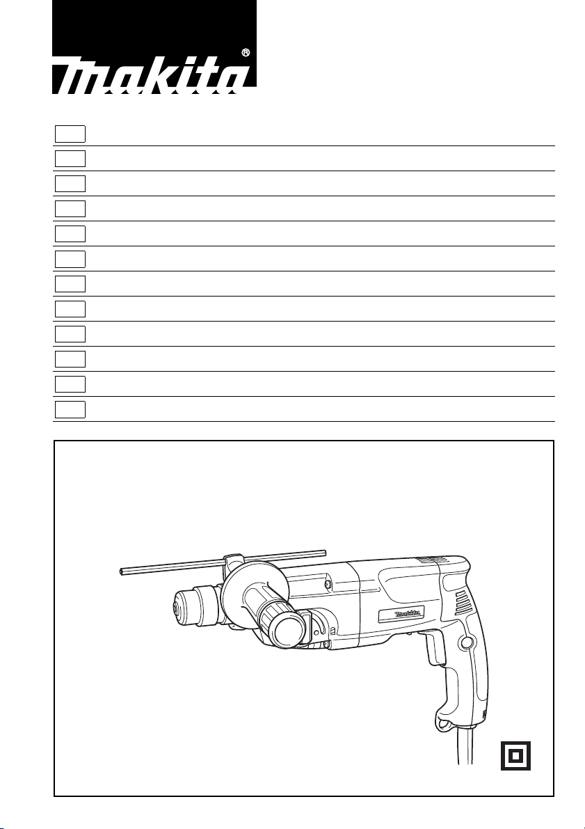
Rotary Hammer Instruction Manual
F
Perforateur
D
Bohrhammer Betriebsanleitung
I
Martello rotativo Istruzioni per l’uso
NL
Boorhamer Gebruiksaanwijzing
E
Martillo rotativo Manual de instrucciones
P
Martelo misto Manual de instruções
DK
Borehammer Brugsanvisning
S
Borrhammare Bruksanvisning
N
Borhammer Bruksanvisning
SF
Poravasara Käyttöohje
GR Περιστροφικ σφυρί Οδηγίες χρήσεως
Manuel d’instructions
HR2440
HR2440X
HR2440F
HR2441
HR2442
Page 2
1
3
2
5
4
6
7
8
12
9
10
9
10
34
11
12
13
14
56
A
B
15
13
12
16
78
2
Page 3
18
17
910
21
19
20
11 12
23
24
22
3
Page 4

Symbols
The followings show the symbols used for the tool. Be sure that you understand their meaning before use.
Symboles
Nous donnons ci-dessous les symboles utilisés pour l’outil. Assurez-vous que vous en avez bien compris la signification avant d’utiliser l’outil.
Symbole
Die folgenden Symbole werden für die Maschine verwendet. Machen Sie sich vor der Benutzung unbedingt mit ihrer
Bedeutung vertraut.
Simboli
Per questo utensile vengono usati i simboli seguenti. Bisogna capire il loro significato prima di usare l’utensile.
Symbolen
Voor dit gereedschap worden de volgende symbolen gebruikt. Zorg ervoor dat u de betekenis van deze symbolen
begrijpt alvorens het gereedschap te gebruiken.
Símbolos
A continuación se muestran los símbolos utilizados con esta herramienta. Asegúrese de que entiende su significado
antes de usarla.
Símbolos
O seguinte mostra os símbolos utilizados para a ferramenta. Certifique-se de que compreende o seu significado antes
da utilização.
Symboler
Nedenstående symboler er anvendt i forbindelse med denne maskine. Vær sikker på, at De har forstået symbolernes
betydning, før maskinen anvendes.
Symboler
Det följande visar de symboler som används för den här maskinen. Se noga till att du förstår deras innebörd innan
maskinen används.
Symbolene
Følgende viser de symblene som brukes for maskinen. Det er viktig å forstå betydningen av disse før maskinen tas i
bruk.
Symbolit
Alla on esitetty koneessa käytetyt symbolit. Opettele näiden merkitys, ennen kuin käytät konetta.
Σύµβολα
Τα ακλουθα δείχνουν τα σύµβολα που χρησιµοποιούνται για το µηχάνηµα. Βεβαιωθείτε τι καταλαβαίνετε
τη σηµασία τους πριν απ τη χρήση.
❏ Read instruction manual.
❏ Lire le mode d’emploi.
❏ Bitte Betriebsanleitung lesen.
❏ Leggete il manuale di istruzioni.
❏ Lees de gebruiksaanwijzing.
❏ Lea el manual de instrucciones.
❏ DOUBLE INSULATION
❏ DOUBLE ISOLATION
❏ DOPPELT SCHUTZISOLIERT
❏ DOPPIO ISOLAMENTO
❏ DUBBELE ISOLATIE
❏ DOBLE AISLAMIENTO
❏ Leia o manual de instruções.
❏ Læs brugsanvisningen.
❏ Läs bruksanvisningen.
❏ Les bruksanvisingen.
❏ Katso käyttöohjeita.
❏ ∆ιαβάστε τις οδηγίες χρήσης.
❏ DUPLO ISOLAMENTO
❏ DOBBELT ISOLATION
❏ DUBBEL ISOLERING
❏ DOBBEL ISOLERING
❏ KAKSINKERTAINEN ERISTYS
❏ ∆ΙΠΛΗ ΜΟΝΩΣΗ
4
Page 5

ENGLISH
Explanation of general view
1Grip base
2 Side grip (auxiliary handle)
3Teeth
4 Protrusions
5 Loosen
6Tighten
7 Bit shank
8Bit grease
SPECIFICATIONS
Model HR2440/HR2440X/HR2440F HR2441 HR2442
Capacities
Concrete
Tungsten-carbide tipped bit................ 24mm 24mm 24mm
Core bit .............................................. 54mm 54mm 54mm
Diamond core bit (dry type) ............... 65mm 65mm 65mm
Wood .................................................... 32 mm 32 mm 32 mm
Steel ..................................................... 13mm 13 mm 13mm
No load speed (min
Blows per minute ..................................... 0– 4,500 0 –4,500 4,500
Overall length .......................................... 352mm 352 mm 352mm
Net weight................................................ 2.3 kg 2.3kg 2.3 kg
-1
).............................. 0– 1,100 0 – 1,100 1,100
9Bit
10 Chuck cover
11 Depth gauge
12 Switch trigger
13 Lock button
14 Lamp (HR2440F only)
15 Reversing switch lever
16 Action mode changing knob
17 Blow-out bulb
18 Dust cup
19 Chuck adapter
20 Keyless drill chuck
21 Sleeve
22 Ring
23 Tighten
24 Loosen
• Due to our continuing program of research and development, the specifications herein are subject to change
without notice.
• Note: Specifications may differ from country to country.
Intended use
The tool is intended for hammer drilling and drilling in
brick, concrete and stone. It is also suitable for drilling
without impact in wood, metal, ceramic and plastic.
Power supply
The tool should be connected only to a power supply of
the same voltage as indicated on the nameplate, and can
only be operated on single-phase AC supply. They are
double-insulated in accordance with European Standard
and can, therefore, also be used from sockets without
earth wire.
Safety hints
For your own safety, please refer to the enclosed safety
instructions.
ADDITIONAL SAFETY RULES
1. Hold tools by insulated gripping surfaces when
performing an operation where the cutting tool
may contact hidden wiring or its own cord. Contact with a “live” wire will make exposed metal
parts of the tool “live” and shock the operator.
2. Wear ear protectors when using the tool for
extended periods. Prolonged exposure to high
intensity noise can cause hearing loss.
ENB010-1
3. Wear a hard hat (safety helmet), safety glasses
and/or face shield. It is also highly recommended that you wear a dust mask, and thickly
padded gloves.
4. Be sure the bit is secured in place before operation.
5. Under normal operation, the tool is designed to
produce vibration. The screws can come loose
easily, causing a breakdown or accident. Check
tightness of screws carefully before operation.
6. In cold weather or when the tool has not been
used for a long time, let the tool warm up for a
while by operating it under no load. This will
loosen up the lubrication. Without proper warmup, hammering operation is difficult.
7. Always be sure you have a firm footing.
Be sure no one is below when using the tool in
high locations.
8. Hold the tool firmly with both hands.
9. Keep hands away from moving parts.
10. Do not leave the tool running. Operate the tool
only when hand-held.
11. Do not point the tool at any one in the area when
operating. The bit could fly out and injure someone seriously.
12. Do not touch the bit or parts close to the bit
immediately after operation; they may be
extremely hot and could burn your skin.
SAVE THESE INSTRUCTIONS.
5
Page 6

OPERATING INSTRUCTIONS
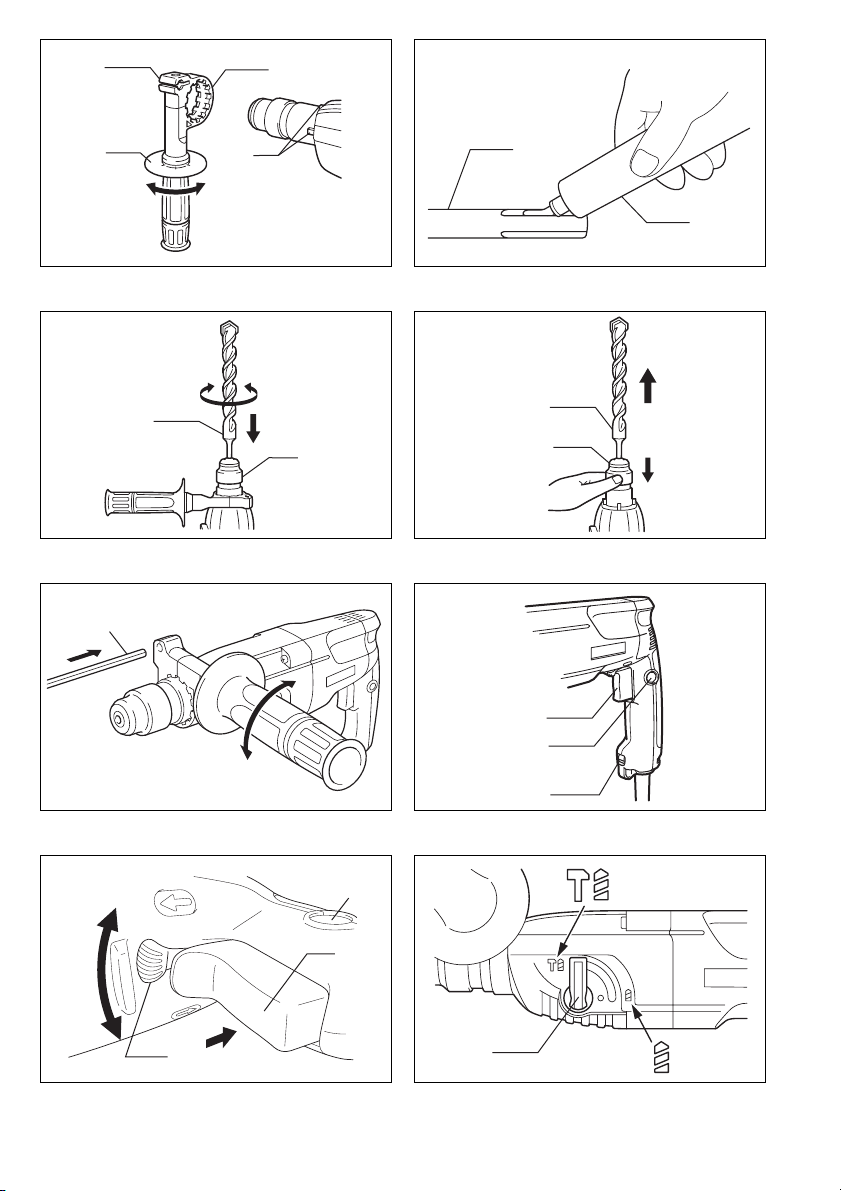
Side grip (auxiliary handle) (Fig. 1)
Always use the side grip to ensure operating safety.
Install the side grip so that the teeth on the grip fit in
between the protrusions on the tool barrel. Then tighten
the grip by turning clockwise at the desired position. It
may be swung 360° so as to be secured at any position.
Installing or removing the bit
CAUTION:
Always be sure that the tool is switched off and
unplugged before installing or removing the bit.
Clean the bit shank and apply bit grease before installing
the bit. (Fig. 2)
Insert the bit into the tool. Turn the bit and push it in until
it engages. (Fig. 3)
After installing, always make sure that the bit is securely
held in place by trying to pull it out.
To remove the bit, pull the chuck cover down all the way
and pull the bit out. (Fig. 4)
Depth gauge (Fig. 5)
The depth gauge is convenient for drilling holes of uniform depth. Loosen the side grip and insert the depth
gauge into the hole in the side grip. Adjust the depth
gauge to the desired depth and tighten the side grip.
NOTE:
The depth gauge cannot be used at the position where
the depth gauge strikes against the gear housing.
Switch action (Fig. 6)
CAUTION:
Before plugging in the tool, always check to see that the
switch trigger actuates properly and returns to the “OFF”
position when released.
For Model HR2440, HR2440X, HR2440F and HR2441
To start the tool, simply pull the switch trigger. Tool speed
is increased by increasing pressure on the switch trigger.
Release the switch trigger to stop. For continuous operation, pull the switch trigger and then push in the lock button. To stop the tool from the locked position, pull the
switch trigger fully, then release it.
For Model HR2442
To start the tool, simply pull the switch trigger. Release
the switch trigger to stop. For continuous operation, pull
the switch trigger and then push in the lock button. To
stop the tool from the locked position, pull the switch trigger fully, then release it.
Lighting up the lamps (Fig. 6)
For Model HR2440F
CAUTION:
Do not look in the light or see the source of light directly.
To turn on the lamp, pull the trigger. Release the trigger
to turn it off.
NOTE:
Use a dry cloth to wipe the dirt off the lens of lamp. Be
careful not to scratch the lens of lamp, or it may lower the
illumination.
Reversing switch action (Fig. 7)
For Model HR2440, HR2440X, HR2440F
This tool has a reversing switch to change the direction of
rotation. Move the reversing switch lever to the
tion (A side) for clockwise rotation or to the
(B side) for counterclockwise rotation.
CAUTION:
• Always check the direction of rotation before operation.
• Use the reversing switch only after the tool comes to a
complete stop. Changing the direction of rotation
before the tool stops may damage the tool.
• When you operate the tool in counterclockwise rotation,
the switch trigger is pulled only halfway and the tool
runs at half speed. For counterclockwise rotation, you
cannot push in the lock button.
E
D
posi-
position
Selection action mode (Fig. 8)
This tool employs an action mode changing knob. Select
one of the two modes suitable for your work needs by
using this knob. For rotation only, turn the knob so that
the arrow on the knob points toward the
the tool body. For rotation with hammering, turn the knob
so that the arrow on the knob points toward the
bol on the tool body.
CAUTION:
• Always set the knob fully to your desired mode symbol.
If you operate the tool with the knob positioned halfway between the mode symbols, the tool may be damaged.
• Use the knob after the tool comes to a complete stop.
M
symbol on
r
sym-
Torque limiter
The torque limiter will actuate when a certain torque level
is reached. The motor will disengage from the output
shaft. When this happens, the bit will stop turning.
CAUTION:
• As soon as the torque limiter actuates, switch off the
tool immediately. This will help prevent premature wear
of the tool.
• Hole saws cannot be used with this tool. They tend to
pinch or catch easily in the hole. This will cause the
torque limiter to actuate too frequently.
Hammer drilling operation
Position the bit at the desired location for the hole, then
pull the trigger.
Do not force the tool. Light pressure gives best results.
Keep the tool in position and prevent it from slipping away
from the hole.
Do not apply more pressure when the hole becomes
clogged with chips or particles. Instead, run the tool at an
idle, then remove the bit partially from the hole. By
repeating this several times, the hole will be cleaned out
and normal drilling may be resumed.
CAUTION:
There is tremendous and sudden twisting force exerted
on the tool/bit at the time of hole breakthrough, when the
hole becomes clogged with chips and particles, or when
striking reinforcing rods embedded in the concrete.
Always use the side grip (auxiliary handle) and firmly
hold the tool by both side grip and switch handle during
operations. Failure to do so may result in the loss of control of the tool and potentially severe injury.
6
Page 7

NOTE:
Eccentricity in the bit rotation may occur while operating
the tool with no load. The tool automatically centers itself
during operation. This does not affect the drilling precision.
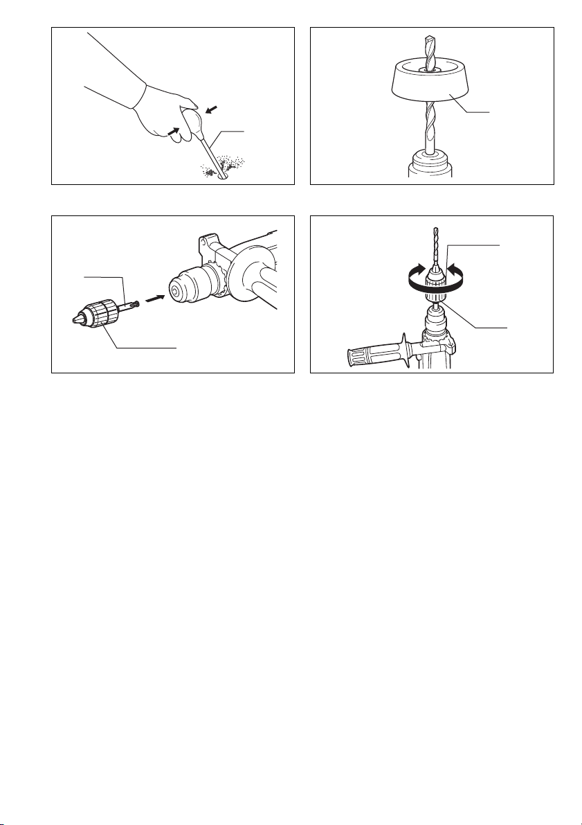
Bit grease
Coat the bit shank head beforehand with a small amount
of bit grease (about 0.5 – 1 g).
This chuck lubrication assures smooth action and longer
service life.
Blow-out bulb (Fig. 9)
Use the blow-out bulb to clean out the hold.
Dust cup (Fig. 10)
Use the dust cup to prevent dust from falling over the tool
and on yourself when performing overhead drilling operations. Attach the dust cup to the bit as shown in Fig. 10.
The size of bits which the dust cup can be attached to is
as follows.
Bit diameter (mm)
Dust cup 5 6 – 14.5
Dust cup 9 12 – 16
Drilling in wood or metal (Fig. 11 and 12)
Use the optional drill chuck assembly (standard equipment for Model HR2440X). When installing it, refer to
“Installing or removing drill bit” described on the previous
page.
Hold the ring and turn the sleeve counterclockwise to
open the chuck jaws. Place the bit in the chuck as far as it
will go. Hold the ring firmly and turn the sleeve clockwise
to tighten the chuck.
To remove the bit, hold the ring and turn the sleeve counterclockwise. Set the action mode changing knob to
“rotation only”. You can drill up to 13 mm diameter in
metal and up to 32 mm diameter in wood.
CAUTION:
• Never use “rotation with hammering” when the drill
chuck assembly is installed on the tool. The drill chuck
assembly may be damaged.
Also, the drill chuck will come off when reversing the
tool. (For Model HR2440, HR2440X, HR2440F)
• Pressing excessively on the tool will not speed up the
drilling. In fact, this excessive pressure will only serve
to damage the tip of your bit, decrease the tool performance and shorten the service life of the tool.
• There is a tremendous twisting force exerted on the
tool/bit at the time of hole breakthrough. Hold the tool
firmly and exert care when the bit begins to break
through the workpiece.
• A stuck bit can be removed simply by setting the
reversing switch to reverse rotation in order to back out.
However, the tool may back out abruptly if you do not
hold it firmly.
• Always secure small workpieces in a vise or similar
hold-down device.
• When performing diamond core drilling operation,
always set the change lever to the
rotation only” action. If performing diamond core
“
drilling operation with
action, the diamond core bit may be damaged.
M position to use
rotation with hammering
“
MAINTENANCE
CAUTION:
Always be sure that the tool is switched off and
unplugged before carrying out any work on the tool.
To maintain product safety and reliability, repairs, maintenance or adjustment should be carried out by a Makita
Authorized Service Center.
”
7
Page 8

NEDERLANDS
Verklaring van algemene gegevens
1 Handgreepvoet
2 Zijhandgreep (hulphandgreep)
3 Tanden
4 Nokken
5 Losdraaien
6 Vastzetten
7 Boorschacht
8Boorvet
TECHNISCHE GEGEVENS
Model HR2440/HR2440X/HR2440F HR2441 HR2442
Vermogen
Beton
Boor met wolfraamcarbide-boorpunt .....24 mm 24 mm 24 mm
Kernboor................................................54 mm 54 mm 54 mm
Diamantkernboor (droog type) ..............65 mm 65mm 65 mm
Hout ...........................................................32 mm 32mm 32 mm
Staal ..........................................................13 mm 13 mm 13 mm
Nullasttoerental (min
Aantal slagen/minuut ....................................0 –4 500 0 –4 500 4 500
Totale lengte .................................................352 mm 352mm 352 mm
Netto gewicht................................................2,3 kg 2,3 kg 2,3 kg
-1
).................................0 – 1 100 0 – 1 100 1 100
9Boor
10 Boorkopdeksel
11 Dieptemaat
12 Trekschakelaar
13 Vastzetknop
14 Lamp (alleen voor HR2440F)
15 Omkeerschakelaarknop
16 Omschakelknop
17 Blaasbalgje
18 Stofvanger
19 Boorkop-adapter
20 Sleutelloze boorkop
21 Bus
22 Ring
23 Vastzetten
24 Losdraaien
• In verband met ononderbroken research en ontwikkeling behouden wij ons het recht voor bovenstaande
technische gegevens te wijzigen zonder voorafgaande
kennisgeving.
• Opmerking: De technische gegevens kunnen van land
tot land verschillen.
Doeleinden van gebruik
Het gereedschap is bedoeld voor hamerboren en boren
in baksteen, beton en steen. Het is ook geschikt voor
boren zonder slag in hout, metaal, keramisch materiaal
en kunststof.
Stroomvoorziening
Het gereedschap mag alleen worden aangesloten op
een stroombron van hetzelfde voltage als aangegeven op
de naamplaat, en kan alleen op enkel-fase wisselstroom
worden gebruikt. Het gereedschap is dubbel-geïsoleerd
volgens de Europese standaard en kan derhalve ook op
een niet-geaard stopcontact worden aangesloten.
Veiligheidswenken
Voor uw veiligheid dient u de bijgevoegde Veiligheidsvoorschriften nauwkeurig op te volgen.
AANVULLENDE
VEILIGHEIDSVOORSCHRIFTEN
1. Houd het gereedschap tijdens het werk vast bij
de geïsoleerde handgrepen wanneer er kans is
dat de boor op verborgen elektrische draden of
op zijn eigen netsnoer zal stoten. Door contact
met onder spanning staande draden zullen de
metalen delen van het gereedschap onder spanning komen te staan zodat de gebruiker een
elektrische schok kan krijgen.
2. Draag oorbeschermers wanneer u het gereed-
schap voor langere tijd doorlopend gebruikt.
Langdurige blootstelling aan sterk lawaai kan
gehoorverlies veroorzaken.
3. Draag een hard hoofddeksel (veiligheidshelm),
een veiligheidsbril en/of gezichtsbescherming.
Het is ook zeer aan te bevelen een stofmasker en
dikke handschoenen te dragen.
4. Controleer of de boor goed vastgezet is alvorens
met uw werk te beginnen.
5. Tijdens normale bediening brengt dit gereedschap trillingen voort. De schroeven kunnen
daarom gemakkelijk loskomen, met een defect of
ongeluk als mogelijk gevolg.
6. Controleer vóór het gebruik of alle schroeven
goed vastzitten. Laat het gereedschap een tijdje
onbelast warmdraaien wanneer het koud weer is
of wanneer het gereedschap voor langere tijd
niet werd gebruikt. Hierdoor zal het smeermiddel
vloeibaar worden. Hameren is moeilijk indien het
gereedschap niet goed warmgedraaid is.
7. Zorg ervoor dat u altijd stevige steun voor de
voeten hebt.
Controleer of er zich niemand beneden u bevindt
wanneer u het gereedschap op een hoge plaats
gaat gebruiken.
8. Houd het gereedschap stevig vast met beide
handen.
9. Houd uw handen uit de buurt van draaiende
onderdelen.
10. Laat het gereedschap niet achter terwijl het nog
in bedrijf is. Bedien het gereedschap alleen wanneer u het met beide handen vasthoudt.
11. Richt het gereedschap tijdens het gebruik niet
op personen die zich in de nabije omgeving
bevinden. De boor zou kunnen losraken en ernstige verwondingen veroorzaken.
12. Raak de boor of onderdelen in de nabije omgeving van de boor niet aan onmiddellijk na het
gebruik; deze kunnen erg heet zijn en brandwonden veroorzaken.
BEWAAR DEZE VOORSCHRIFTEN.
17
Page 9

BEDIENINGSVOORSCHRIFTEN
Zijhandgreep (hulphandgreep) (Fig. 1)
Gebruik altijd de zijhandgreep om een veilige bediening
te verzekeren. Installeer de zijhandgreep zodanig dat de
tanden op de greep tussen de nokken op het huis van de
machine komen te zitten. Zet dan de handgreep vast
door deze in de gewenste positie naar rechts te draaien.
De handgreep kan 360° worden verdraaid zodat u deze
in elke gewenste positie kunt vastzetten.
Aanbrengen of verwijderen van de boor
LET OP:
Controleer altijd of het gereedschap is uitgeschakeld en
zijn stekker uit het stopcontact is verwijderd alvorens de
boor aan te brengen of te verwijderen.
Reinig de boorschacht en smeer er boorvet op alvorens
de boor te installeren. (Fig. 2)
Steek de boor in de machine. Draai de boor en duw deze
naar binnen tot zij vergrendelt. (Fig. 3)
Nadat de boor is geïnstalleerd, moet u altijd controleren
of de boor goed vastzit door te proberen hem eruit te
trekken.
Om de boor te verwijderen, trekt u het boorkopdeksel
helemaal omlaag en dan trekt u de boor eruit. (Fig. 4)
Diepteaanslag (Fig. 5)
De diepteaanslag is handig voor het boren van gaten van
gelijke diepte. Maak de zijhandgreep los en steek de
diepteaanslag in het gat in de zijhandgreep. Stel de diepteaanslag af op de gewenste diepte en zet de zijhandgreep vast.
OPMERKING:
De diepteaanslag kan niet worden gebruikt in de positie
waarbij deze tegen het tandwielhuis aanstoot.
Werking van de trekschakelaar (Fig. 6)
LET OP:
Alvorens de machine op een stopcontact aan te sluiten,
moet u altijd controleren of de trekschakelaar juist werkt
en bij het loslaten naar de “OFF” positie terugkeert.
Voor HR2440, HR2440X, HR2440F en HR2441
Om de machine te starten, drukt u gewoon de trekschakelaar in. Hoe dieper de trekschakelaar wordt ingedrukt,
hoe sneller de machine draait. Om de machine uit te
schakelen, de trekschakelaar loslaten. Voor continuë
werking, drukt u de trekschakelaar in en dan drukt u de
vastzetknop in. Om de machine vanuit deze vergrendelde stand te stoppen, de trekschakelaar volledig
indrukken en deze dan loslaten.
Voor HR2442
Om de machine te starten, drukt u gewoon de trekschakelaar in. Om de machine uit te schakelen, de trekschakelaar loslaten. Voor continuë werking, drukt u de
trekschakelaar in en dan drukt u de vastzetknop in. Om
de machine vanuit deze vergrendelde stand te stoppen,
de trekschakelaar volledig indrukken en deze dan loslaten.
Aanzetten van de lampen
Voor Model HR2440F
LET OP:
Kijk niet direct in het licht of de lichtbron.
Druk de trekker in om de lamp aan te zetten. Laat de
trekker los om de lamp uit te doen.
OPMERKING:
Gebruik een droge doek om vuil op de lamplens eraf te
vegen. Let op dat u geen krassen maakt op de lamplens,
aangezien de verlichtingssterkte daardoor zal verminderen.
(Fig. 6)
Werking van de omkeerschakelaar (Fig. 7)
Voor HR2440, HR2440X, HR2440F
Dit gereedschap heeft een omkeerschakelaar voor het
veranderen van de draairichting. Schuif de omkeerschakelaar naar de positie
richting, of naar de positie
draairichting.
LET OP:
• Controleer altijd de draairichting alvorens de machine
te gebruiken.
• Gebruik de omkeerschakelaar alleen nadat de machine
volledig tot stilstand is gekomen. Indien u de draairichting verandert voordat de machine is gestopt, kan de
machine beschadigd raken.
• Wanneer u het gereedschap in linkse draairichting
gebruikt, kan de trekschakelaar alleen tot halverwege
worden ingedrukt en draait het gereedschap op halve
snelheid. Voor linkse draairichting kunt u de vergrendelknop niet indrukken.
D
(zijde A) voor rechtse draai-
E
(zijde B) voor linkse
Kiezen van de bedieningsfunctie (Fig. 8)
Dit gereedschap heeft een omschakelknop. Gebruik
deze knop voor het kiezen van een van de twee bedieningsfuncties die geschikt is voor uw werk. Voor roteren
alleen, draai de knop zodanig dat het pijltje op de knop
naar het
schap wijst. Voor roteren met hameren, draai de knop
zodanig dat het pijltje op de knop naar het
op het lichaam van het gereedschap wijst.
LET OP:
• Zet de knop altijd volledig op het gewenste symbool.
• Gebruik de knop pas nadat het gereedschap tot volle-
M
symbool op het lichaam van het gereed-
r
symbool
Indien u het gereedschap gebruikt met de knop halverwege tussen de twee symbolen geplaatst, kan het
gereedschap beschadigd raken.
dige stilstand is gekomen.
Koppelbegrenzer
De koppelbegrenzer treedt in werking wanneer de motor
een bepaald koppel bereikt. De motor wordt dan ontkoppeld van de uitgangsas. Wanneer dit gebeurt, zal de boor
ophouden met draaien.
LET OP:
• Schakel het gereedschap onmiddellijk uit wanneer de
koppelbegrenzer in werking treedt. Hierdoor helpt u
vroegtijdige slijtage van het gereedschap voorkomen.
• Gatenzagen kunnen met dit gereedschap niet worden
gebruikt. Deze lopen of klemmen gemakkelijk vast in
het boorgat, zodat de koppelbegrenzer te vaak in werking zal worden gesteld.
18
Page 10

Hamerend of kloppend boren
Plaats de punt van de boor op de gewenste plaats waar
geboord moet worden, en druk vervolgens de schakelaar
in.
Forceer het gereedschap niet. Een lichte druk geeft de
beste resultaten. Houd het gereedschap stevig vast en
zorg dat het niet uitglijdt.
Oefen geen grotere druk uit wanneer het boorgat verstopt raakt met schilfertjes of metaaldeeltjes. Laat in zo’n
geval het gereedschap onbelast lopen en verwijder de
boor gedeeltelijk uit het boorgat. Wanneer dit verschillende keren wordt herhaald, zal het boorgat schoon worden en kunt u normaal verder boren.
LET OP:
Op het moment dat een gat wordt geboord, of wanneer
het boorgat verstopt raakt met schilfertjes en metaaldeeltjes, of wanneer de machine op versterkingsstaven in
gewapend beton stoot, wordt er plotseling een enorme
wringingskracht op de machine/boor uitgeoefend.
Gebruik daarom altijd de zijhandgreep (hulphandgreep)
en houd de machine tijdens het gebruik stevig vast bij
zowel de zijhandgreep als de hoofdhandgreep. Indien u
dit verzuimt, kunt u de controle over de machine verliezen en mogelijk zware verwondingen oplopen.
OPMERKING:
Terwijl het gereedschap onbelast wordt gebruikt, kan de
boor excentrisch draaien. Het gereedschap centreert
zichzelf automatisch tijdens het gebruik. Dit heeft geen
nadelige invloed op de nauwkeurigheid van het boren.
Invetten van de boor
Voordat u de boor aanbrengt, smeer een beetje vet
(ca. 0,5 tot 1,0 gram) op de kop van de boorschacht.
Met een ingevette boorkop zal het gereedschap beter
werken en langer meegaan.
Blaasbalgje (Fig. 9)
Gebruik het blaasbalgje om het gat schoon te maken.
Stofvanger (Fig. 10)
Gebruik de stofvanger om te voorkomen dat stof op de
machine en op uzelf terechtkomt wanneer u boven uw
hoofd boort. Bevestig de stofvanger aan de boor, zoals
getoond in Fig. 10. De diameter van de boren waaraan
de stofvanger kan worden bevestigd, is als volgt.
Boordiameter (mm)
Stofvanger 5 6 – 14,5
Stofvanger 9 12 – 16
Boren in hout of metaal (Fig. 11en12)
Gebruik de los verkrijgbare boorkopmontage (standaard
accessoire voor Model HR2440X). Om deze te installeren, zie “Aanbrengen of verwijderen van de boor” op de
vorige pagina.
Houd de ring op zijn plaats en draai de bus naar links om
de boorkopklauwen te openen. Duw de boor zo ver
mogelijk in de boorkop. Houd de ring goed vast en draai
de bus naar rechts om de boorkop vast te zetten.
Om de boor te verwijderen, houdt u de ring op zijn plaats
en draait u de bus naar links. Zet de omschakelknop op
“alleen roteren”. U kunt boren tot een diameter van maximaal 13 mm in metaal en een diameter van maximaal
32 mm in hout.
LET OP:
• Gebruik nooit “roteren met hameren” wanneer de boorkop op het gereedschap is gemonteerd. De boorkop
kan hierdoor namelijk beschadigd raken.
Bovendien zal de boorkop loskomen wanneer de draairichting van het gereedschap wordt omgekeerd.
(Voor HR2440, HR2440X, HR2440F)
• Door teveel druk op het gereedschap uit te oefenen
verloopt het boren niet sneller. Integendeel, teveel druk
op het gereedschap zal alleen maar de boor beschadigen, de prestatie van het gereedschap verminderen en
de gebruiksduur verkorten.
• Er ontstaan enorme spanningen op het ogenblik dat de
boor uit het gat tevoorschijn komt. Houd derhalve het
gereedschap stevig vast en wees op uw hoede.
• Wanneer de boor klemraakt, keert u met de omkeerschakelaar de draairichting om, om de boor uit het gat
te krijgen. Pas echter op en houd het gereedschap stevig vast, aangezien het anders uit het gat weg kan
schieten.
• Kleine werstukken dient u altijd eerst vast te zetten met
een klemschroef of iets dergelijks.
• Wanneer u gaat boren met de diamantkernboor, moet
u de keuzehendel altijd op de “
boren” zetten. Als u de diamantkernboor gebruikt in de
positie “boren plus hameren”, kan de diamantkernboor
beschadigd raken.
M
” positie voor “alleen
ONDERHOUD
LET OP:
Zorg er altijd voor dat het gereedschap is uitgeschakeld
en de stekker uit het stopcontact is verwijderd alvorens
werken aan de machine uit te voeren.
Opdat het gereedschap veilig en betrouwbaar blijft, dienen alle reparaties, onderhoud of afstellingen te worden
uitgevoerd bij een erkend Makita service centrum.
19
 Loading...