

Makita HR2400 User Manual
GB
Rotary Hammer Instruction Manual
F
Marteau perforateur Manuel d’instructions
D
Bohrhammer Betriebsanleitung
I
Martello rotativo Istruzioni d’uso
NL
Boorhamer Gebruiksaanwijzing
E
Martillo rotativo Manual de instrucciones
P
Martelo perfurador Manual de instruções
DK
Borehammer Brugsanvisning
S
Borrhammare Bruksanvisning
N
Borhammer Bruksanvisning
SF
Poravasara Käyttöohje
GR Περιστροφικ σφυρί Οδηγίες χρήσεως
HR2400
3
2
4
1
12
4
5
67
34
8
9
10
11
56
12 14 13
16
15
78
2

ENGLISH
1 Bit grease
2 Bit shank
3Bit
4Chuck cover
5 Wing bolt
6 Depth gauge
Explanation of general view
7 Side grip
8 Switch trigger
9Lock lever
10 Reversing switch
11 Action mode changing knob
12 Chisel adapter
13 Chisel
14 Clamp screw
15 Drill chuck
16 Chuck adapter
SPECIFICATIONS
Model HR2400
Capacities
Concrete ............................................................ 24 mm
Wood ...............................................................* 38 mm
Steel .................................................................. 13 mm
No load speed (min
Blows per minute .............................................. 0 – 4,200
Overall length ..................................................... 333 mm
Net weight .............................................................. 2.3 kg
* When using a flat boring bit.
• Due to our continuing program of research and devel-
opment, the specifications herein are subject to change
without notice.
• Note: Specifications may differ from country to country.
Power supply
The tool should be connected only to a power supply of
the same voltage as indicated on the nameplate, and can
only be operated on single-phase AC supply. They are
double-insulated in accordance with European Standard
and can, therefore, also be used from sockets without
earth wire.
Safety hints
For your own safety, please refer to the enclosed safety
instructions.
–1
) ...................................... 0 – 1,200
SPECIFIC SAFETY RULES
DO NOT let comfort or familiarity with product
(gained from repeated use) replace strict adherence
to rotary hammer safety rules. If you use this tool
unsafely or incorrectly, you can suffer serious personal injury.
1. Wear ear protectors. Exposure to noise can cause
hearing loss.
2. Use auxiliary handles supplied with the tool.
Loss of control can cause personal injury.
3. Hold power tools by insulated gripping surfaces
when performing an operation where the cutting
tool may contact hidden wiring or its own cord.
Contact with a “live” wire will make exposed metal
parts of the tool “live” and shock the operator.
4. Wear a hard hat (safety helmet), safety glasses
and/or face shield. Ordinary eye or sun glasses
are NOT safety glasses. It is also highly recommended that you wear a dust mask and thickly
padded gloves.
5. Be sure the bit is secured in place before opera-
tion.
6. Under normal operation, the tool is designed to
produce vibration. The screws can come loose
easily, causing a breakdown or accident. Check
tightness of screws carefully before operation.
GEB007-2
7. In cold weather or when the tool has not been
used for a long time, let the tool warm up for a
while by operating it under no load. This will
loosen up the lubrication. Without proper warmup, hammering operation is difficult.
8. Always be sure you have a firm footing.
Be sure no one is below when using the tool in
high locations.
9. Hold the tool firmly with both hands.
10. Keep hands away from moving parts.
11. Do not leave the tool running. Operate the tool
only when hand-held.
12. Do not point the tool at any one in the area when
operating. The bit could fly out and injure someone seriously.
13. Do not touch the bit or parts close to the bit
immediately after operation; they may be
extremely hot and could burn your skin.
14. Some material contains chemicals which may be
toxic. Take caution to prevent dust inhalation
and skin contact. Follow material supplier safety
data.
SAVE THESE INSTRUCTIONS.
WARNING:
MISUSE or failure to follow the safety rules stated in
this instruction manual may cause serious personal
injury.
OPERATING INSTRUCTIONS
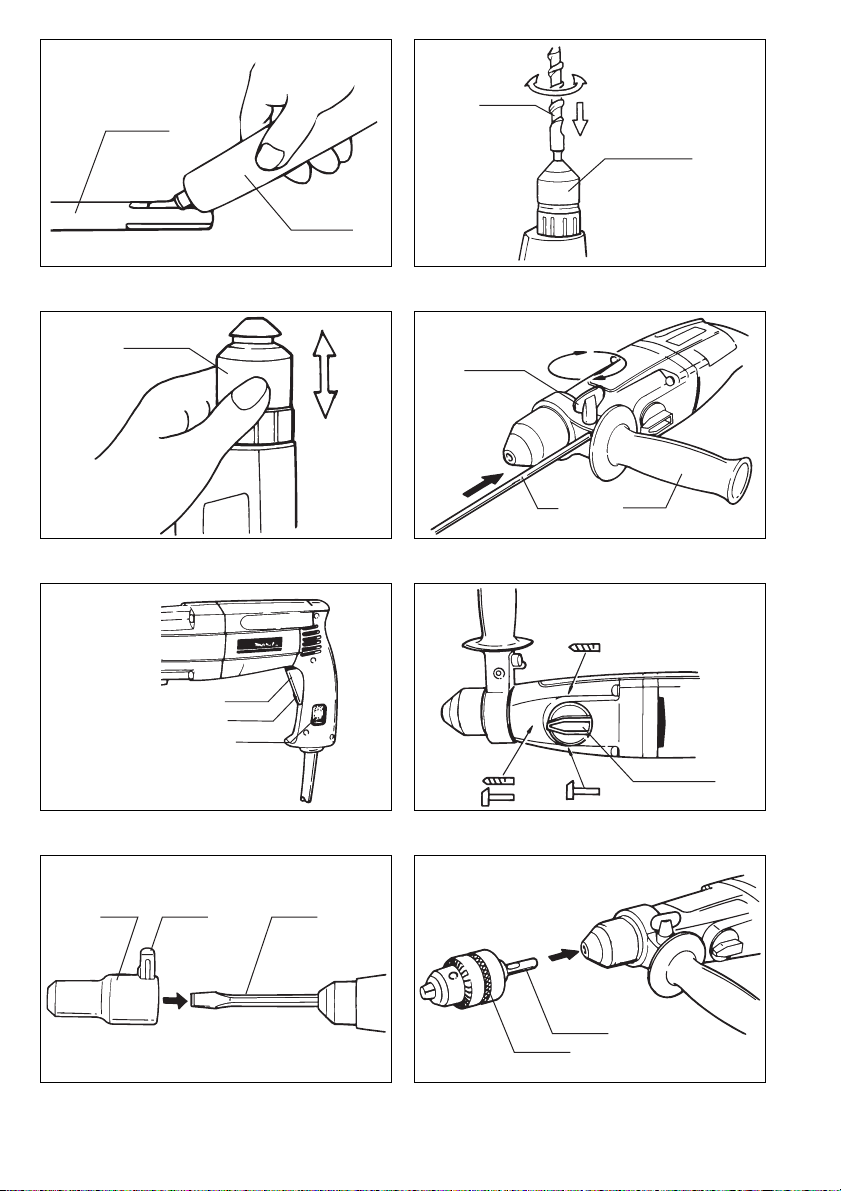
Installing or removing drill bit (Fig. 1, 2 & 3)
Important:
Always be sure that the tool is switched off and
unplugged before installing or removing the bit.
Clean the bit shank and apply bit grease before installing
the bit. (Fig. 1)
Insert the bit into the tool. Turn the bit and push it in until
it engages. (Fig. 2)
If the bit cannot be pushed in, remove the bit. Pull the
chuck cover down a couple of times. Then insert the bit
again. Turn the bit and push it in until it engages. (Fig. 3)
After installing, always make sure that the bit is securely
held in place by trying to pull it out.
To remove the bit, pull the chuck cover down all the way
and pull the bit out. (Fig. 4)
3

Adjusting depth of drilling (Fig. 4)
Loosen the wing bolt and adjust the depth gauge to the
desired depth. After adjusting, tighten the wing bolt.
NOTE:
The depth gauge cannot be used at the position where
the depth gauge strikes against the gear housing.
Side grip (Auxiliary handle) (Fig. 4)
The side grip swings around to either side, allowing easy
handling of the tool in any position. Loosen the wing bolt
on the side grip and swing the side grip to the desired
position. Then tighten the wing bolt to secure the side
grip.
Operating instruction (Fig. 5)
Important:
Before plugging in the tool, always check to see that the
switch trigger actuates properly and returns to the “OFF”
position when released.
Switching ON and OFF (Fig. 5)
To switch on, press the trigger.
To switch off, release the trigger.
Continuous running (Fig. 5)
Press the trigger and at the same time slide the lock lever
upward. To stop from this lock position, press the trigger
and release it.
Variable trigger speed control (Fig. 5)
The speed varies from 0 to maximum, depending on the
pressure applied to the trigger. The more the trigger is
pressed, the faster the tool runs.
Reversing switch (Fig. 5)
Important:
Only reverse the direction of rotation when the motor
stops completely.
To change the direction of rotation:
Position FWD: right hand rotation
Position REV: left hand rotation
Three selecting action modes (Fig. 6)
For hammer drilling:
Turn the knob so that the arrow points toward the
symbol.
For drilling only:
Turn the knob so that the arrow points toward the
symbol.
For hammering only:
Turn the knob so that the arrow points toward the
symbol.
NOTE:
When it is hard to turn the knob, pull the switch trigger
half-way for running at low speed and turn the knob.
Torque limiter
The torque limiter will actuate when a certain torque level
is reached. The motor will disengage from the output
shaft. When this happens, the bit will stop turning.
CAUTION:
As soon as the torque limiter actuates, switch off the tool
immediately. This will help prevent premature wear of the
tool. Hole saws, core bit, diamond core bit, etc. cannot be
used with this tool. They tend to pinch or catch easily in
the hole. This will cause the torque limiter to actuate too
frequently.
Using cold chisel or bull point (Fig. 7)
1. Disconnect plug.
2. Remove the side grip from the tool.
3. Turn the knob to hammer drilling symbol .
4. Install the cold chisel or bull point and then the chisel
adapter (optional accessory) on the tool.
5. Rotate the cold chisel toward the direction suitable
for your work. Then secure the cold chisel and chisel
adapter by using the clamp screw on the chisel
adapter.
6. Turn the knob to hammering only symbol . Now
you can use the cold chisel or bull point.
NOTE:
Always set “hammering only” action when using the cold
chisel or bull point. If you use “hammer drilling” or “drilling
only” action, the hammering mechanism may be damaged on the tool.
Drilling in wood or metal (Fig. 8)
Use the optional drill chuck assembly (consisting of drill
chuck and chuck adapter assembly). When installing it,
refer to “installing or removing drill bit” described on the
previous page. Set the knob to “drilling only”. You can drill
up to 13 mm diameter in metal and up to 38 mm diameter in wood. (Note: When using a flat boring bit.)
NOTE:
Never set “hammer drilling” action when using the drill
chuck assembly because it may be damaged and come
off when reversing the tool.
MAINTENANCE
CAUTION:
Always be sure that the tool is switched off and
unplugged before carrying out any work on the tool.
To maintain product safety and reliability, repairs, maintenance or adjustment should be carried out by a Makita
Authorized Service Center.
4
 Loading...