

Page 1
INSTRUCTION MANUAL
MANUEL D'INSTRUCTION
MANUAL DE INSTRUCCIONES
Rotary Hammer
Marteau rotatif
Martillo rotativo
HR1830
HR1830F
007227
DOUBLE INSULATION
DOUBLE ISOLATION
DOBLE AISLAMIENTO
WARNING:
For your personal safety, READ and UNDERSTAND before using.
SAVE THESE INSTRUCTIONS FOR FUTURE REFERENCE.
AVERTISSEMENT:
Pour votre propre sécurité, prière de lire attentivement avant l’utilisation.
GARDER CES INSTRUCTIONS POUR RÉFÉRENCE ULTÉRIEURE.
ADVERTENCIA:
Para su seguridad personal, LEA DETENIDAMENTE este manual antes de usar la herramienta.
GUARDE ESTAS INSTRUCCIONES PARA FUTURA REFERENCIA.
Page 2

ENGLISH
SPECIFICATIONS
Model HR1830 / HR1830F
Concrete 18 mm (11/16”)
Core bit 35 mm (1-3/8”)
Capacities
No load speed (RPM) 0 - 1,500/min.
Blows per minute 0 - 5,000
• Due to our continuing programme of research and development, the specifications herein are subject to change
without notice.
• Note: Specifications may differ from country to country.
Diamond core bit (dry type) 65 mm (2-9/16”)
Steel 13 mm (1/2”)
Wood 24 mm (15/16”)
Overall length 279 mm (10-7/8”)
Net weight 1.7 kg (3.7 lbs)
GENERAL SAFETY RULES
USA002-2
(For All Tools)
WARNING:
Read and understand all instructions.
Failure to follow all instructions listed below,
may result in electric shock, fire and/or serious personal injury.
SAVE THESE INSTRUCTIONS
Work Area
1. Keep your work area clean and well lit. Cluttered
benches and dark areas invite accidents.
2. Do not operate power tools in explosive atmo-
spheres, such as in the presence of flammable
liquids, gases, or dust. Power tools create sparks
which may ignite the dust or fumes.
3. Keep bystanders, children, and visitors away
while operating a power tool. Distractions can
cause you to lose control.
Electrical Safety
4. Double insulated tools are equipped with a
polarized plug (one blade is wider than the
other.) This plug will fit in a polarized outlet only
one way. If the plug does not fit fully in the outlet,
reverse the plug. If it still does not fit, contact a
qualified electrician to install a polarized outlet.
Do not change the plug in any way. Double insula-
tion eliminates the need for the three wire
grounded power cord and grounded power supply
system.
5. Avoid body contact with grounded surfaces
such as pipes, radiators, ranges and refrigerators. There is an increased risk of electric shock if
your body is grounded.
6. Do not expose power tools to rain or wet conditions. Water entering a power tool will increase the
risk of electric shock.
7. Do not abuse the cord. Never use the cord to
carry the tools or pull the plug from an outlet.
Keep cord away from heat, oil, sharp edges or
moving parts. Replace damaged cords immediately. Damaged cords increase the risk of electric
shock.
8. When operating a power tool outside, use an
outdoor extension cord marked “W-A” or “W”.
These cords are rated for outdoor use and reduce
the risk of electric shock.
Personal Safety
9. Stay alert, watch what you are doing and use
common sense when operating a power tool. Do
not use tool while tired or under the influence of
drugs, alcohol, or medication. A moment of inat-
tention while operating power tools may result in
serious personal injury.
10. Dress properly. Do not wear loose clothing or
jewelry. Contain long hair. Keep your hair, clothing, and gloves away from moving parts. Loose
clothes, jewelry, or long hair can be caught in moving parts.
11. Avoid accidental starting. Be sure switch is off
before plugging in. Carrying tools with your finger
2
Page 3

on the switch or plugging in tools that have the
switch on invites accidents.
12. Remove adjusting keys or wrenches before turning the tool on. A wrench or a key that is left
attached to a rotating part of the tool may result in
personal injury.
13. Do not overreach. Keep proper footing and balance at all times. Proper footing and balance
enables better control of the tool in unexpected situations.
14. Use safety equipment. Always wear eye protection. Dust mask, non-skid safety shoes, hard hat, or
hearing protection must be used for appropriate conditions. Ordinary eye or sun glasses are NOT eye
protection.
Tool Use and Care
15. Use clamps or other practical way to secure and
support the workpiece to a stable platform. Hold-
ing the work by hand or against your body is unstable and may lead to loss of control.
16. Do not force tool. Use the correct tool for your
application. The correct tool will do the job better
and safer at the rate for which it is designed.
17. Do not use tool if switch does not turn it on or
off. Any tool that cannot be controlled with the
switch is dangerous and must be repaired.
18. Disconnect the plug from the power source
before making any adjustments, changing
accessories, or storing the tool. Such preventive
safety measures reduce the risk of starting the tool
accidentally.
19. Store idle tools out of reach of children and
other untrained persons. Tools are dangerous in
the hands of untrained users.
20. Maintain tools with care. Keep cutting tools
sharp and clean. Properly maintained tools with
sharp cutting edges are less likely to bind and are
easier to control.
21. Check for misalignment or binding of moving
parts, breakage of parts, and any other condition
that may affect the tools operation. If damaged,
have the tool serviced before using. Many acci-
dents are caused by poorly maintained tools.
22. Use only accessories that are recommended by
the manufacturer for your model. Accessories
that may be suitable for one tool, may become hazardous when used on another tool.
SERVICE
23. Tool service must be performed only by qualified
repair personnel. Service or maintenance per-
formed by unqualified personnel could result in a risk
of injury.
24. When servicing a tool, use only identical
replacement parts. Follow instructions in the
Maintenance section of this manual. Use of unau-
thorized parts or failure to follow Maintenance
instructions may create a risk of electric shock or
injury.
USE PROPER EXTENSION CORD: Make sure your
extension cord is in good condition. When using an
extension cord, be sure to use one heavy enough to
carry the current your product will draw. An undersized
cord will cause a drop in line voltage resulting in loss of
power and overheating. Table 1 shows the correct size to
use depending on cord length and nameplate ampere
rating. If in doubt, use the next heavier gage. The smaller
the gage number, the heavier the cord.
Table 1: Minimum gage for cord
Ampere Rating
Volts Total length of cord in feet
120 V 25 ft. 50 ft. 100 ft. 150 ft.
More Than Not More Than AWG
0 6 18 16 16 14
18 16 14 12610
10 12 16 16 14 12
12 16 14 12
Not Recommended
3
Page 4
SPECIFIC SAFETY RULES
USB010-2
DO NOT let comfort or familiarity with
product (gained from repeated use)
replace strict adherence to rotary hammer safety rules. If you use this tool
unsafely or incorrectly, you can suffer
serious personal injury.
1. Hold tools by insulated gripping surfaces when
performing an operation where the cutting tool
may contact hidden wiring or its own cord. Con-
tact with a “live” wire will make exposed metal parts
of the tool “live” and shock the operator.
2. Wear ear protectors when using the tool for
extended periods. Prolonged exposure to high
intensity noise can cause hearing loss.
3. Wear a hard hat (safety helmet), safety glasses
and/or face shield. Ordinary eye or sun glasses
are NOT safety glasses. It is also highly recommended that you wear a dust mask and thickly
padded gloves.
4. Be sure the bit is secured in place before operation.
5. Under normal operation, the tool is designed to
produce vibration. The screws can come loose
easily, causing a breakdown or accident. Check
tightness of screws carefully before operation.
6. In cold weather or when the tool has not been
used for a long time, let the tool warm up for a
while by operating it under no load. This will
loosen up the lubrication. Without proper warmup, hammering operation is difficult.
7. Always be sure you have a firm footing.
Be sure no one is below when using the tool in
high locations.
8. Hold the tool firmly with both hands.
9. Keep hands away from moving parts.
10. Do not leave the tool running. Operate the tool
only when hand-held.
11. Do not point the tool at any one in the area when
operating. The bit could fly out and injure someone seriously.
12. Do not touch the bit or parts close to the bit
immediately after operation; they may be
extremely hot and could burn your skin.
13. Some material contains chemicals which may be
toxic. Take caution to prevent dust inhalation
and skin contact. Follow material supplier safety
data.
SAVE THESE INSTRUCTIONS
WARNING:
MISUSE or failure to follow the safety
rules stated in this instruction manual
may cause serious personal injury.
SYMBOLS
The followings show the symbols used for tool.
V ...........................volts
A...........................amperes
Hz .........................hertz
.................. alternating current
.......................no load speed
.......................Class II Construction
.../min ...................revolutions or reciprocation per
minute
.................. number of blow
USD202-2
FUNCTIONAL DESCRIPTION
CAUTION:
• Always be sure that the tool is switched off and
unplugged before adjusting or checking function on
the tool.
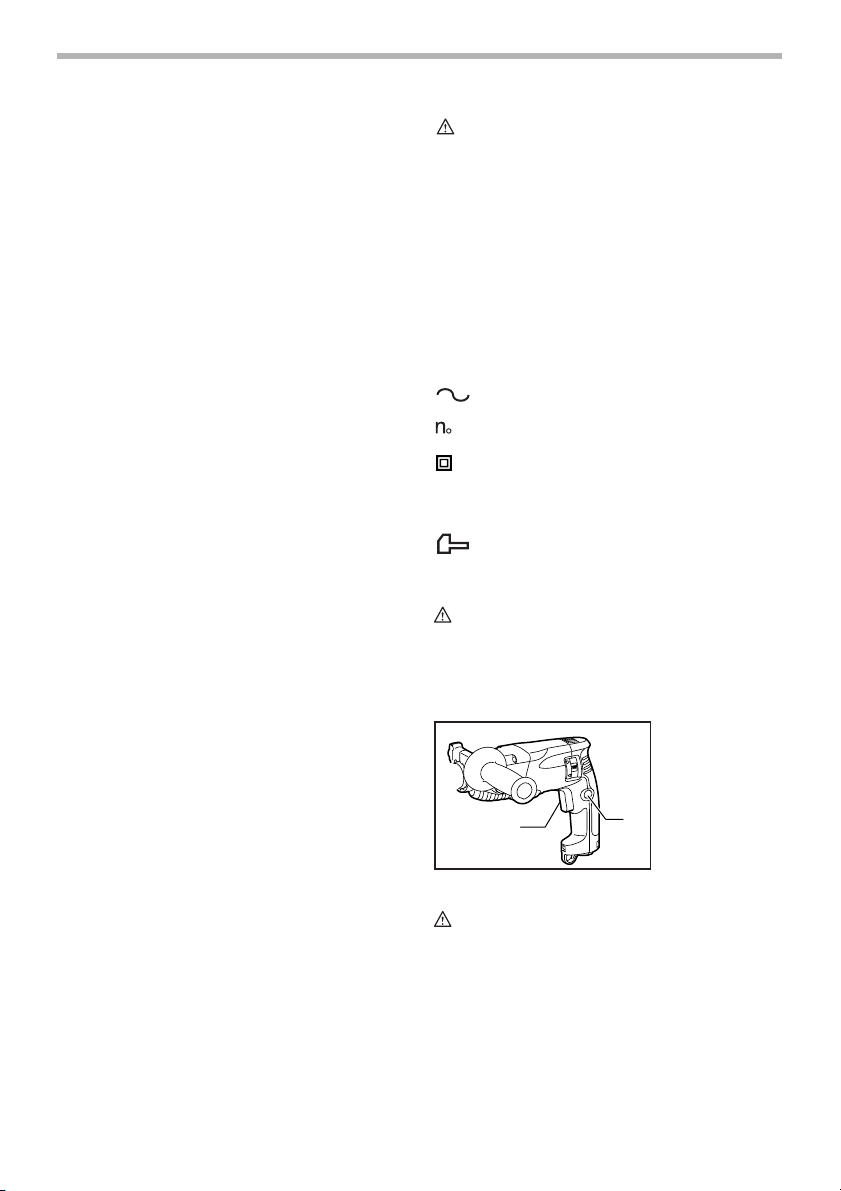
Switch action
1
CAUTION:
• Before plugging in the tool, always check to see
that the switch trigger actuates properly and returns
to the “OFF” position when released.
To start the tool, simply pull the switch trigger. Tool speed
is increased by increasing pressure on the switch trigger.
Release the switch trigger to stop. For continuous operation, pull the switch trigger and then push in the lock button. To stop the tool from the locked position, pull the
switch trigger fully, then release it.
007228
1. Switch trigger
2. Lock button
2
4
Page 5
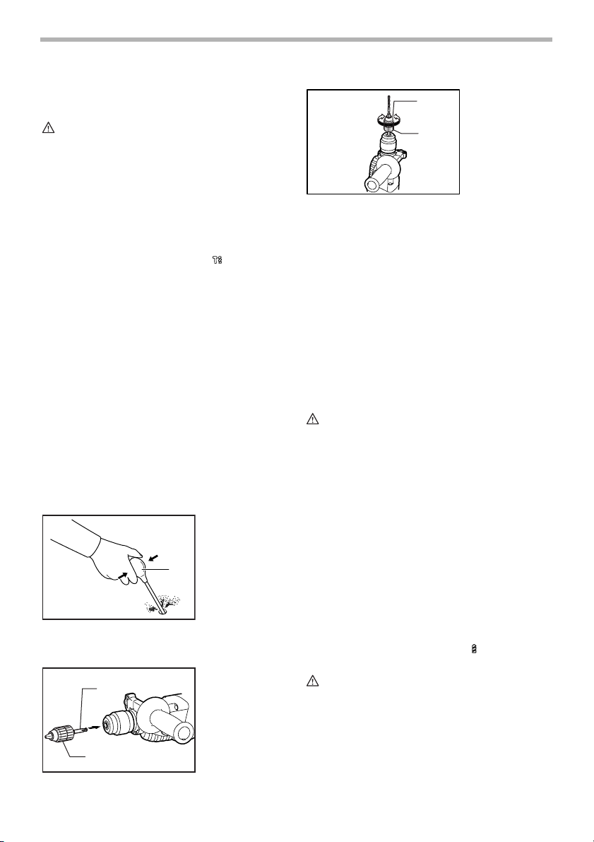
Lighting up the lamps
For Model HR1830F only
007229
1. Lamp
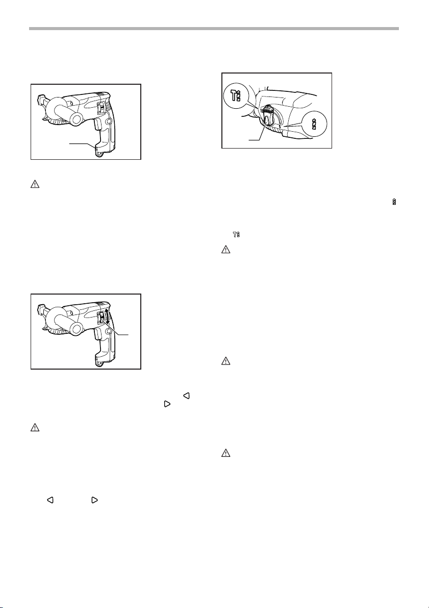
Selecting the action mode
007231
1. Action mode
changing knob
1
CAUTION:
• Do not look in the light or see the source of light
directly.
To turn on the lamp, pull the trigger. Release the trigger
to turn it off.
NOTE:
• Use a dry cloth to wipe the dirt off the lens of lamp.
Be careful not to scratch the lens of lamp, or it may
lower the illumination.
Reversing switch action
This tool has a reversing switch to change the direction of
rotation. Move the reversing switch lever to the position (A side) for clockwise rotation or the position (B
side) for counterclockwise rotation.
CAUTION:
• Always check the direction of rotation before opera-
tion.
• Use the reversing switch only after the tool comes
to a complete stop. Changing the direction of rotation before the tool stops may damage the tool.
• If the switch trigger can not be depressed, check to
see that the reversing switch is fully set to position
(A side) or (B side).
007230
1. Reversing
B
A
switch
1
1
This tool employs an action mode changing knob. Select
one of the two modes suitable for your work needs by
using this knob.
For rotation only, depress the lock button and turn the
knob so that the arrow on the knob points toward the
symbol on the tool body.
For rotation with hammering, depress the lock button and
turn the knob so that the arrow on the knob points toward
the symbol on the tool body.
CAUTION:
• Always set the knob fully to your desired mode
symbol. If you operate the tool with the knob positioned halfway between the mode symbols, the tool
may be damaged.
• Use the knob after the tool comes to a complete
stop.
Torque limiter
The torque limiter will actuate when a certain torque level
is reached. The motor will disengage from the output
shaft. When this happens, the bit will stop turning.
CAUTION:
• As soon as the torque limiter actuates, switch off
the tool immediately. This will help prevent premature wear of the tool.
• Hole saws cannot be used with this tool. They tend
to pinch or catch easily in the hole. This will cause
the torque limiter to actuate too frequently.
ASSEMBLY
CAUTION:
• Always be sure that the tool is switched off and
unplugged before carrying out any work on the tool.
5
Page 6
Side grip (auxiliary handle)
1
5
007232
6
2
3
4
1. Grip base
2. Side grip
3. Loosen
4. Tighten
5. Teeth
6. Protrusion
To remove the bit, pull the chuck cover down all the way
and pull the bit out.
1
007234
1. Bit
2. Chuck cover
2
CAUTION:
• Always use the side grip to ensure operating safety.
Install the side grip so that the teeth on the grip fit in
between the protrusions on the tool barrel. Then tighten
the grip by turning clockwise at the desired position. It
may be swung 360° so as to be secured at any position.
Bit grease
Coat the bit shank head beforehand with a small amount
of bit grease (about 0.5 - 1 g).
This chuck lubrication assures smooth action and longer
service life.
Installing or removing the bit
1
Clean the bit shank and apply bit grease before installing
the bit.
Insert the bit into the tool. Turn the bit and push it in until
it engages.
After installing, always make sure that the bit is securely
held in place by trying to pull it out.
1
001296
1. Bit shank
2. Bit grease
2
007233
1. Bit
2. Chuck cover
2
Depth gauge
1
2
007235
4
1. Depth gauge
2. Hole of grip
base
3. Loosen
3
4. Tighten
The depth gauge is convenient for drilling holes of uniform depth. Loosen the side grip and insert the depth
gauge into the hole in the side grip. Adjust the depth
gauge to the desired depth and tighten the side grip.
NOTE:
• The depth gauge cannot be used at the position
where the depth gauge strikes against the gear
housing.
Dust cup
001300
1. Dust cup
1
Use the dust cup to prevent dust from falling over the tool
and on yourself when performing overhead drilling operations. Attach the dust cup to the bit as shown in the figure. The size of bits which the dust cup can be attached
to is as follows.
Dust cup 5 6 mm (1/4") - 14.5 mm (9/16")
Dust cup 9 12 mm (15/32") - 16 mm (5/8")
Bit diameter
006382
6
Page 7
OPERATION
Hammer drilling operation
CAUTION:
• There is a tremendous and sudden twisting force
exerted on the tool/bit at the time of hole breakthrough, when the hole becomes clogged with
chips and particles, or when striking reinforcing
rods embedded in the concrete. Always use the
side grip (auxiliary handle) and firmly hold the tool
by both side grip and switch handle during operations. Failure to do so may result in the loss of control of the tool and potentially severe injury.
When drilling in concrete, granite, etc., move the action
mode changing knob to the position of symbol to use
“rotation with hammering” action.
Be sure to use a tungsten-carbide tipped bit.
Position the bit at the desired location for the hole, then
pull the switch trigger. Do not force the tool. Light pressure gives best results. Keep the tool in position and prevent it from slipping away from the hole.
Do not apply more pressure when the hole becomes
clogged with chips or particles. Instead, run the tool at an
idle, then remove the bit partially from the hole. By
repeating this several times, the hole will be cleaned out
and normal drilling may be resumed.
NOTE:
Eccentricity in the bit rotation may occur while operating
the tool with no load. The tool automatically centers itself
during operation. This does not affect the drilling precision.
Blow-out bulb (optional accessory)
After drilling the hole, use the blow-out bulb to clean the
dust out of the hole.
Drilling in wood or metal
1
001302
1. Blow-out bulb
1
007236
1. Keyless drill
chuck
2. Chuck adapter
007237
1
2
Use the optional drill chuck assembly. When installing it,
refer to “Installing or removing drill bit” described on the
previous page.
Hold the ring and turn the sleeve counterclockwise to
open the chuck jaws. Place the bit in the chuck as far as
it will go. Hold the ring firmly and turn the sleeve clockwise to tighten the chuck.
To remove the bit, hold the ring and turn the sleeve counterclockwise. Set the action mode changing knob to
“rotation only”.
You can drill up to 13 mm diameter in metal and up to
24 mm diameter in wood.
Never use “rotation with hammering” when the drill chuck
assembly is installed on the tool. The drill chuck assembly may be damaged.
Also, the drill chuck will come off when reversing the tool.
CAUTION:
• Pressing excessively on the tool will not speed up
the drilling. In fact, this excessive pressure will only
serve to damage the tip of your bit, decrease the
tool performance and shorten the service life of the
tool.
• There is a tremendous twisting force exerted on the
tool/bit at the time of hole breakthrough. Hold the
tool firmly and exert care when the bit begins to
break through the workpiece.
• A stuck bit can be removed simply by setting the
reversing switch to reverse rotation in order to back
out. However, the tool may back out abruptly if you
do not hold it firmly.
• Always secure small workpieces in a vise or similar
hold-down device.
1. Sleeve
2. Ring
Diamond core drilling
When performing diamond core drilling operations,
always set the change lever to the position to use
“rotation only” action.
CAUTION:
• If performing diamond core drilling operations using
“rotation with hammering” action, the diamond core
bit may be damaged.
2
7
Page 8

MAINTENANCE
CAUTION:
• Always be sure that the tool is switched off and
unplugged before attempting to perform inspection
or maintenance.
To maintain product SAFETY and RELIABILITY, repairs,
carbon brush inspection and replacement, any other
maintenance or adjustment should be performed by Makita Authorized or Factory Service Centers, always using
Makita replacement parts.
ACCESSORIES
CAUTION:
• These accessories or attachments are recom-
mended for use with your Makita tool specified in
this manual. The use of any other accessories or
attachments might present a risk of injury to persons. Only use accessory or attachment for its
stated purpose.
If you need any assistance for more details regarding
these accessories, ask your local Makita Service Center.
• SDS-Plus Carbide-tipped bits
• Core bit
• Diamond core bit
• Drill chuck assembly
• Drill chuck S13
• Chuck adapter
• Chuck key S13
• Bit grease
• Side grip
• Depth gauge
• Blow-out bulb
• Dust cup
• Dust extractor attachment
• Safety goggles
• Plastic carrying case
• Keyless drill chuck
MAKITA LIMITED ONE YEAR WARRANTY
Warranty Policy
Every Makita tool is thoroughly inspected and tested
before leaving the factory. It is warranted to be free of
defects from workmanship and materials for the period of
ONE YEAR from the date of original purchase. Should
any trouble develop during this one year period, return
the COMPLETE tool, freight prepaid, to one of Makita’s
Factory or Authorized Service Centers. If inspection
shows the trouble is caused by defective workmanship or
material, Makita will repair (or at our option, replace)
without charge.
This Warranty does not apply where:
• repairs have been made or attempted by others:
EN0006-1
• repairs are required because of normal wear and
tear:
• the tool has been abused, misused or improperly
maintained:
• alterations have been made to the tool.
IN NO EVENT SHALL MAKITA BE LIABLE FOR ANY
INDIRECT, INCIDENTAL OR CONSEQUENTIAL DAMAGES FROM THE SALE OR USE OF THE PRODUCT.
THIS DISCLAIMER APPLIES BOTH DURING AND
AFTER THE TERM OF THIS WARRANTY.
MAKITA DISCLAIMS LIABILITY FOR ANY IMPLIED
WARRANTIES, INCLUDING IMPLIED WARRANTIES
OF “MERCHANTABILITY” AND “FITNESS FOR A SPECIFIC PURPOSE,” AFTER THE ONE YEAR TERM OF
THIS WARRANTY.
This Warranty gives you specific legal rights, and you
may also have other rights which vary from state to state.
Some states do not allow the exclusion or limitation of
incidental or consequential damages, so the above limitation or exclusion may not apply to you. Some states do
not allow limitation on how long an implied warranty lasts,
so the above limitation may not apply to you.
8
Page 9

FRANÇAIS
SPÉCIFICATIONS
Modèle HR1830 / HR1830F
Béton 18 mm (11/16”)
Tr épan 35 mm (1-3/8”)
Capacités
Vitesse à vide (T/MIN) 0 - 1,500/min.
Nombre de frappes par minute 0 - 5,000
• Le fabricant se réserve le droit de modifier sans avertissement les spécifications.
• Note: Les spécifications peuvent varier selon les pays.
Foret au diamant (type à sec) 65 mm (2-9/16”)
Acier 13 mm (1/2”)
Bois 24 mm (15/16”)
Longueur totale 279 mm (10-7/8”)
Poids net 1.7 kg (3.7 lbs)
RÈGLES DE SÉCURITÉ
GÉNÉRALES
USA002-2
(Pour tous les outils)
AVERTISSEMENT:
Vous devez lire et comprendre toutes les
instructions. Le non-respect, même partiel,
des instructions ci-après entraîne un risque
de choc électrique, d’incendie et/ou de
blessures graves.
CONSERVEZ CES
INSTRUCTIONS
Aire de travail
1. Veillez à ce que l’aire de travail soit propre et
bien éclairée. Le désordre et le manque de lumière
favorisent les accidents.
2. N’utilisez pas d’outils électriques dans une
atmosphère explosive, par exemple en présence
de liquides, de gaz ou de poussières
inflammables. Les outils électriques créent des
étincelles qui pourraient enflammer les poussières
ou les vapeurs.
3. Tenez à distance les curieux, les enfants et les
visiteurs pendant que vous travaillez avec un
outil électrique. lls pourraient vous distraire et vous
faire une fausse manoeuvre.
Sécurité électrique
4. Les outils à double isolation sont équipés d’une
fiche polarisée (une des lames est plus large que
l’autre), qui ne peut se brancher que d'une seule
façon dans une prise polarisée. Si la fiche
n’entre pas parfaitement dans la prise, inversez
sa position ; si elle n’entre toujours pas bien,
demandez à un électricien qualifié d’installer une
prise de courant polarisée. Ne modifiez pas la
fiche de l’outil. La double isolation élimine le
besoin d’un cordon d’alimentation à trois fils avec
mise à la terre ainsi que d’une prise de courant mise
à la terre.
5. Évitez tout contact corporel avec des surfaces
mises à la terre (tuyauterie, radiateurs,
cuisinières, réfrigérateurs, etc.). Le risque de
choc électrique est plus grand si votre corps est en
contact avec la terre.
6. N’exposez pas les outils électriques à la pluie ou
à l’eau. La présence d’eau dans un outil électrique
augmente le risque de choc électrique.
7. Ne maltraitez pas le cordon. Ne transportez pas
l’outil par son cordon et ne débranchez pas la
fiche en tirant sur le cordon. N’exposez pas le
cordon à la chaleur, à des huiles, à des arêtes
vives ou à des pièces en mouvement.
Remplacez immédiatement un cordon
endommagé. Un cordon endommagé augmente le
risque de choc électrique.
8. Lorsque vous utilisez un outil électrique à
l’extérieur, employez un prolongateur pour
l’extérieur marqué “W-A” ou “W”. Ces cordons
sont faits pour être utilisés à l’extérieur et réduisent
le risque de choc électrique.
9
Page 10

Sécurité des personnes
9. Restez alerte, concentrez-vous sur votre travail
et faites preuve de jugement. N’utilisez pas un
outil électrique si vous êtes fatigué ou sous
l'influence de drogues, d’alcool ou de
médicaments. Un instant d’inattention suffit pour
entraîner des blessures graves.
10. Habillez-vous convenablement. Ne portez ni
vêtements flottants ni bijoux. Confinez les
cheveux longs. N’approchez jamais les
cheveux, les vêtements ou les gants des pièces
en mouvement. Des vêtements flottants, des bijoux
ou des cheveux longs risquent d’être happés par
des pièces en mouvement.
11. Méfiez-vous d’un démarrage accidentel. Avant
de brancher l’outil, assurez-vous que son
interrupteur est sur ARRÊT. Le fait de transporter
un outil avec le doigt sur la détente ou de brancher
un outil dont l’interrupteur est en position MARCHE
peut mener tout droit à un accident.
12. Enlevez les clés de réglage ou de serrage avant
de démarrer l’outil. Une clé laissée dans une pièce
tournante de l’outil peut provoquer des blessures.
13. Ne vous penchez pas trop en avant. Maintenez
un bon appui et restez en équilibre en tout
temps. Un bonne stabilité vous permet de mieux
réagir à une situation inattendue.
14. Utilisez des accessoires de sécurité. Portez
toujours des lunettes ou une visière. Selon les
conditions, portez aussi un masque antipoussière,
des bottes de sécurité antidérapantes, un casque
protecteur et/ou un appareil antibruit. Les lunettes
ordinaires et les lunettes de soleil NE constituent
PAS des lunettes de protection.
Utilisation et entretien des outils
15. Immobilisez le matériau sur une surface stable
au moyen de brides ou de toute autre façon
adéquate. Le fait de tenir la pièce avec la main ou
contre votre corps offre une stabilité insuffisante et
peut amener un dérapage de l’outil.
16. Ne forcez pas l’outil. Utilisez l’outil approprié à
la tâche. L’outil correct fonctionne mieux et de façon
plus sécuritaire. Respectez aussi la vitesse de
travail qui lui est propre.
17. N’utilisez pas un outil si son interrupteur est
bloqué. Un outil que vous ne pouvez pas
commander par son interrupteur est dangereux et
doit être réparé.
18. Débranchez la fiche de l’outil avant d’effectuer
un réglage, de changer d’accessoire ou de
ranger l’outil. De telles mesures préventives de
sécurité réduisent le risque de démarrage accidentel
de l’outil.
19. Rangez les outils hors de la portée des enfants
et d’autres personnes inexpérimentées. Les
outils sont dangereux dans les mains d’utilisateurs
novices.
20. Prenez soin de bien entretenir les outils. Les
outils de coupe doivent être toujours bien
affûtés et propres. Des outils bien entretenus, dont
les arêtes sont bien tranchantes, sont moins
susceptibles de coincer et plus faciles à diriger.
21. Soyez attentif à tout désalignement ou
coincement des pièces en mouvement, à tout
bris ou à toute autre condition préjudiciable au
bon fonctionnement de l’outil. Si vous constatez
qu’un outil est endommagé, faites-le réparer
avant de vous en servir. De nombreux accidents
sont causés par des outils en mauvais état.
22. N’utilisez que des accessoires que le fabricant
recommande pour votre modèle d’outil. Certains
accessoires peuvent convenir à un outil, mais être
dangereux avec un autre.
SERVICE
23. La réparation des outils électriques doit être
confiée à un réparateur qualifié. L’entretien ou la
réparation d’un outil électrique par un amateur peut
avoir des conséquences graves.
24. Pour la réparation d’un outil, n’employez que
des pièces de rechange d’origine. Suivez les
directives données à la section «ENTRETIEN» de
ce manuel. L’emploi de pièces non autorisées ou le
non-respect des instructions d’entretien peut créer
un risque de choc électrique ou de blessures.
UTLISEZ UN CORDON PROLONGATEUR ADÉQUAT:
Assurez-vous que le cordon prolongateur est en bon
état. Lors de l’utilisation d’un cordon prolongateur,
utilisez sans faute un cordon assez gros pour conduire le
courant que le produit nécessite. Un cordon trop petit
provoquera une baisse de tension de secteur, résultant
en une perte de puissance et une surchauffe. Le Tableau
1 indique la dimension appropriée de cordon selon sa
longueur et selon l’intensité nominale indiquée sur la
plaque signalétique. En cas de doute sur un cordon
donné, utilisez le cordon suivant (plus gros). Plus le
numéro de gabarit indiqué est petit, plus le cordon est
gros.
10
Page 11

Tableau 1. Gabarit minimum du cordon
é nominale
Intensit
Plus de Pas plus de Calibre am
Volts Longueur totale du cordon en pieds
120 V 25 pi 50 pi 100 pi 150 pi
éricain des fils
0 6 18 16 16 14
18 16 14 12610
10 12 16 16 14 12
12 16 14 12
Non recommand
é
RÈGLES DE SÉCURITÉ
PARTICULI ÈRES
USB010-2
NE vous laissez PAS tromper (au fil d’une
utilisation répétée) par un sentiment
d’aisance et de familiarité avec le
produit, en négligeant le respect
rigoureux des consignes de sécurité qui
accompagnent le marteau perforateur.
L’utilisation non sécuritaire ou incorrecte
de cet outil comporte un risque de
blessure grave.
1. Tenez l’outil par ses surfaces de prise isolées
pendant toute opération où l’outil de coupe
pourrait venir en contact avec un câblage
dissimulé ou avec son propre cordon. En cas de
contact avec un conducteur sous tension, les pièces
métalliques à découvert de l’outil transmettraient un
choc électrique à l’utilisateur.
2. Portez un appareil antibruit si vous devez utiliser
l’outil pendant une période prolongée. Une
exposition prolongée à un bruit de forte intensité
peut entraîner des lésions de l’ouïe.
3. Portez un casque rigide (casque de protection)
ainsi que des lunettes de sécurité et/ou un écran
facial. Les lunettes ordinaires et les lunettes de
soleil ne constituent PAS des lunettes de
sécurité. Le port d’un masque à poussière et de
gants épais est également fortement
recommandé.
4. Assurez-vous que le foret est solidement installé
avant l’utilisation.
5. L’outil est conçu pour produire des vibrations
dans des conditions normales d’utilisation. Les
vis peuvent facilement se desserrer et entraîner
une panne ou un accident. Avant l’utilisation,
vérifiez soigneusement si les vis sont bien
serrées.
6. Par temps froid ou lorsque l’outil est resté
inutilisé pendant une longue période, faites-le
réchauffer pendant quelques minutes en le
faisant fonctionner à vide. Cela réchauffera le
lubrifiant. Sans un réchauffement adéquat, le
martelage s’effectue difficilement.
7. Assurez-vous toujours de travailler en position
stable.
Lorsque vous utilisez l’outil dans un endroit
élevé, assurez-vous qu’il n’y a personne en bas.
8. Tenez l’outil fermement à deux mains.
9. Gardez les mains éloignées des pièces en
mouvement.
10. Ne laissez pas l’outil tourner. Ne le faites
fonctionner que lorsque vous le tenez.
11. Ne pointez l’outil vers personne autour de vous
pendant l’utilisation. Le foret pourrait être éjecté
et blesser quelqu’un grièvement.
12. Ne touchez pas le foret ou les parties situées
près du foret immédiatement après l’utilisation ;
ils peuvent être extrêmement chauds et brûler
votre peau.
13. Certains matériaux contiennent des produits
chimiques qui peuvent être toxiques. Prenez les
précautions nécessaires pour éviter que la
poussière dégagée lors du travail ne soit inhalée
ou n’entre en contact avec la peau. Suivez les
consignes de sécurité du fournisseur du
matériau.
CONSERVEZ CE MODE
D'EMPLOI.
AVERTISSEMENT:
Une MAUVAISE UTILISATION de l'outil ou
l'ignorance des consignes de sécurité du
présent manuel d'instructions peuvent
entraîner une grave blessure.
11
Page 12

SYMBOLES
Les symboles utilisés pour l’outil sont présentés cidessous.
V............................volts
A ...........................ampères
Hz..........................hertz
...................courant alternatif
.......................vitesse à vide
.......................construction, catégorie II
.../min....................tours ou alternances par minute
..................nombre de frappes
USD202-2
DESCRIPTION DU
FONCTIONNEMENT
ATTENTION:
• Assurez-vous toujours que l’outil est hors tension et
débranché avant de l’ajuster ou de vérifier son
fonctionnement.
Interrupteur
007228
1. Gâchette
2. Bouton de
verrouillage
Allumage de la lampe
Pour le modèle HR1830F uniquement
1
ATTENTION:
• Evitez de regarder directement le faisceau
lumineux ou sa source.
Pour allumer la lampe, appuyez sur la gâchette. Pour
l’éteindre, relâchez la gâchette.
NOTE:
• Utilisez un chiffon sec pour essuyer la saleté qui
recouvre la lentille de la lampe. Prenez garde de
rayer la lentille de la lampe, pour éviter une
diminution de l’éclairage.
Inverseur
007229
1. Lampe
007230
1. Inverseur
B
A
1
1
ATTENTION:
• Avant de brancher l’outil, assurez-vous toujours
que la gâchette fonctionne correctement et revient
en position d’arrêt une fois relâchée.
Pour mettre l’outil en marche, il suffit de tirer sur la
gâchette. La vitesse de l’outil augmente à mesure que
l’on accroît la pression exercée sur la gâchette. Pour
arrêter l’outil, relâchez la gâchette. Pour obtenir un
fonctionnement continu, tirez sur la gâchette et appuyez
sur le bouton de verrouillage. Pour arrêter l’outil lorsqu’il
fonctionne en continu, tirez à fond sur la gâchette et
relâchez-la.
2
Cet outil est équipé d’un inverseur pour changer le sens
de rotation. Déplacez le levier de l’inverseur sur la
position (côté A) pour une rotation dans le sens des
aiguilles d’une montre, ou sur la position (côté B) pour
une rotation dans le sens contraire des aiguilles d’une
montre.
ATTENTION:
• Vérifiez toujours le sens de rotation avant de mettre
l’outil en marche.
• N’actionnez l’inverseur qu’une fois que l’outil est
complètement arrêté. Si vous changez le sens de
rotation avant l’arrêt de l’outil, vous risquez de
l’endommager.
• S’il n’est pas possible d’enfoncer la gâchette,
assurez-vous que l’inverseur est parfaitement placé
sur la position (côté A) ou (côté B).
12
Page 13

Sélection du mode de fonctionnement
1
007231
1. Bouton de
changement de
mode
Poignée latérale (poignée auxiliaire)
1
2
3
5
4
007232
6
1. Base de la
poignée
2. Poignée latérale
3. Desserrer
4. Serrer
5. Dents
6. Saillie
L’outil possède un bouton de changement de mode.
Sélectionnez l’un des deux modes en fonction de la
nature du support.
Pour une rotation seulement, enfoncez le bouton de
verrouillage et tournez le bouton de sorte que la flèche
du bouton pointe vers le symbole sur le bâti de l’outil.
Pour une rotation avec martelage, enfoncez le bouton de
verrouillage et tournez le bouton de sorte que la flèche
du bouton pointe vers le symbole sur le bâti de l’outil.
ATTENTION:
• Placez toujours le bouton parfaitement sur le
symbole du mode désiré. Vous risquez
d’endommager l’outil si vous l’utilisez avec le
bouton placé à mi-chemin entre les symboles de
mode.
• Ne déplacez le bouton qu’une fois l’outil
complètement arrêté.
Limiteur de couple
Le limiteur de couple se déclenche lorsqu’un certain
niveau de couple est atteint. Le moteur se désaccouple
du porte-outil. Dans ce cas, le foret cesse de tourner.
ATTENTION:
• Coupez le contact dès que le limiteur de couple se
déclenche. Ceci permettra d’éviter toute usure
prématurée de l’outil.
• Avec cet outil vous ne pouvez pas utiliser les scies
trepans. Ils ont tendance à se bloquer, déclenchant
constamment le limiteur de couple.
ASSEMBLAGE
ATTENTION:
• Avant d’effectuer toute intervention sur l’outil,
assurez-vous toujours qu’il est hors tension et
débranché.
ATTENTION:
• Utilisez toujours la poignée latérale pour assurer
votre sécurité.
Installez la poignée latérale pour que les dents
s’encastrent parfaitement entre les protubérances du
corps de foret de l’outil. Puis serrez la poignée en
tournant dans le sens des aiguilles d’une montre jusqu’à
la position souhaitée. On la fera tourner à 360° pour être
sécuritaire en toute position.
Graisse rose
Avant de procéder, enduisez la queue du foret d’une
légère couche de graisse (environ 0,5 - 1 g).
Cette lubrification du porte-outil assurera un
fonctionnement en douceur et une longue durée de
service.
Installation et retrait du foret
1
Nettoyez la queue du foret et enduisez-la de graisse à
foret avant d’installer le foret.
Insérez le foret dans l’outil. Tournez le foret puis
enfoncez-le jusqu’à ce qu’il soit engagé.
Après l’installation, vérifiez toujours que le foret est
solidement fixé en essayant de le sortir.
1
001296
1. Queue du foret
2. Graisse à foret
2
007233
1. Embout
2. Couvercle du
mandrin
2
13
Page 14

Pour retirer le foret, tirez le couvercle du mandrin à fond
vers le bas puis dégagez le foret.
1
Gabarit de profondeur
1
2
3
007234
1. Embout
2. Couvercle du
007235
mandrin
1. Jauge de
profondeur
2. Orifice de la
base de la
2
4
poignée
3. Desserrer
4. Serrer
Le gabarit de profondeur vous permet de percer des
trous de même profondeur. Desserrez la poignée latérale
et insérez le gabarit de profondeur dans l’orifice de la
poignée latérale. Réglez le gabarit à la profondeur
désirée puis serrez la poignée latérale.
NOTE:
• Le gabarit de profondeur ne pourra pas être utilisé
dans les positions où son extrémité arrière vient
buter contre le carter.
Collecteur de poussières
001300
1. Collecteur de
poussières
1
UTILISATION
Perçage avec martelage
ATTENTION:
• Une force énorme s’exerce sur le foret et l’outil
lorsque le foret émerge sur la face opposée,
lorsque le trou est encombré de copeaux ou de
particules, ou lors de la frappe sur des barres
d’armature encastrées dans le béton. Utilisez
toujours la poignée latérale (poignée auxiliaire) et
tenez fermement l’outil par la poignée latérale et
par la poignée revolver lors des travaux. Sinon,
vous risquez de perdre le contrôle de l’outil et de
subir une blessure grave.
Lors du perçage dans le béton, le granite, etc., déplacez
le bouton de changement de mode sur la position du
symbole pour utiliser un mouvement de “rotation avec
martelage”.
Assurez-vous d’utiliser un foret à pointe en carbure de
tungstène.
Placez le foret à l’endroit prévu pour le trou, puis
appuyez sur la gâchette. N’appliquez pas une force
excessive sur l’outil. Vous obtiendrez de meilleurs
résultats en exerçant une légère pression. Maintenez
l’outil en position et évitez qu’il ne glisse à l’extérieur du
trou.
N’appliquez pas davantage de pression lorsque le trou
est bouché par les copeaux et particules. Faites plutôt
tourner l’outil au ralenti, puis retirez partiellement le foret
du trou. En répétant cette opération quelques fois, le trou
se débouchera et vous pourrez poursuivre le perçage
normalement.
NOTE:
Lorsque l’outil fonctionne à vide, il se peut que le foret
tourne de manière excentrique. L’outil se centrera lui-
même lors de l’utilisation avec charge. La précision du
perçage n’est donc pas affectée.
Poire soufflante (accessoire en option)
Une fois le trou percé, utilisez la poire soufflante pour
retirer la poussière du trou.
001302
1. Poire soufflante
Pour éviter que la poussière qui s’échappe du trou ne
tombe sur vous lors d’un travail au-dessus de la tête,
utilisez le collecteur de poussières. Engagez le collecteur
sur le foret comme indiqué sur la figure. La taille de forets
qu’il est possible de fixer au collecteur est comme suit.
Collecteur de poussières 5 6 mm (1/4") – 14.5 mm (9/16")
Collecteur de poussières 9 12 mm (15/32") - 16 mm (5/8")
Diamètre du foret
006382
1
14
Page 15

Perçage du bois ou du métal
1
2
Utilisez l’ensemble mandrin en option. Lors de son
installation, reportez-vous à “Installation ou retrait du
foret”, à la page précédente.
Tene z l ’anneau et tournez le manchon dans le sens
inverse des aiguilles d’une montre pour ouvrir les
mâchoires du mandrin. Insérez le foret/l’embout à fond
dans le mandrin. Tenez l’anneau fermement et tournez le
manchon dans le sens des aiguilles d’une montre pour
serrer le mandrin.
Pour retirer le foret, tenez la bague et tournez le
manchon dans le sens contraire des aiguilles d’une
montre. Réglez le bouton de changement de mode sur
“rotation seulement”.
Vous pouvez percer des trous d’un diamètre allant
jusqu’à 13 mm dans le métal et jusqu’à 24 mm dans le
bois.
N’utilisez jamais la “rotation avec martelage” lorsque
l’ensemble mandrin est installé dans l’outil, car vous
pourriez endommager l’ensemble.
Par ailleurs, si vous faites tourner l’outil en sens inverse,
vous risquez de voir l’ensemble mandrin se détacher et
tomber par terre.
ATTENTION:
• Une pression excessive sur l’outil n’accélère pas le
perçage. Au contraire, elle risque d’endommager la
pointe du foret, de réduire le rendement de l’outil et
donc sa durée de service.
• Une force énorme s’exerce sur le foret et l’outil
lorsque le foret émerge sur la face opposée. Tenez
l’outil fermement et faites bien attention lorsque le
foret commence à sortir de la face opposée de la
pièce.
• Un foret coincé peut se retirer en plaçant l’inverseur
sur la direction opposée. Il faut alors faire très
007236
1. Mandrin
autoserrant
2. Adaptateur de
mandrin
007237
1
2
1. Manchon
2. Bague
attention car l’outil risque de reculer brusquement
si vous ne le tenez pas fermement.
• Assurez toujours les petites pièces à percer à l’aide
d’un étau ou d’un mode de fixation analogue.
Perforation au diamant
Lors d'opérations de perforation au diamant, toujours
positionner le levier de changement sur pour l'action
“rotation seulement”.
ATTENTION:
• En cas d’opérations de forage au diamant avec
l’action “rotation avec martelage”, le foret de
diamant peut être endommagé.
ENTRETIEN
ATTENTION:
• Assurez-vous toujours que l’outil est hors tension et
débranché avant d’y effectuer tout travail
d’inspection ou d’entretien.
Pour maintenir la SÉCURITÉ et la FIABILITÉ du produit,
les réparations, l’inspection et le remplacement des
charbons, et tout autre travail d’entretien ou de réglage
doivent être effectués dans une usine ou un centre de
service après-vente Makita agréé, exclusivement avec
des pièces de rechange Makita.
ACCESSOIRES
ATTENTION:
• Ces accessoires ou pièces complémentaires sont
recommandés pour l’utilisation avec l’outil Makita
spécifié dans ce mode d’emploi. L’utilisation de tout
autre accessoire ou pièce complémentaire peut
comporter un risque de blessure. N’utilisez les
accessoires ou pièces qu’aux fins auxquelles ils ont
été conçus.
Si vous désirez obtenir plus de détails concernant ces
accessoires, veuillez contacter le centre de service
après-vente Makita le plus près.
• Foret à pointe en carbure de tungstène SDS-Plus
• Tr épan
• Foret au diamant
• Ensemble mandrin
• Mandrin S13
• Adaptateur de mandrin
• Clé à mandrin S13
• Graisse rose
• Poi gnée latérale
• Gabarit de profondeur
• Poire soufflante
• Collecteur de poussières
• Aspirateur
• Lunettes de sécurité
15
Page 16

• Mallette de transport en plastique
• Mandrin auto-serrant
EN0006-1
GARANTIE LIMITÉE D’UN AN MAKITA
Politique de garantie
Chaque outil Makita est inspecté rigoureusement et testé
avant sa sortie d’usine. Nous garantissons qu’il sera
exempt de défaut de fabrication et de vice de matériau
pour une période d’UN AN à partir de la date de son
achat initial. Si un problème quelconque devait survenir
au cours de cette période d’un an, veuillez retourner
l’outil COMPLET, port payé, à une usine ou à un centre
de service après-vente Makita. Makita réparera l’outil
gratuitement (ou le remplacera, à sa discrétion) si un
défaut de fabrication ou un vice de matériau est
découvert lors de l’inspection.
Cette garantie ne s’applique pas dans les cas où:
• des réparations ont été effectuées ou tentées par
un tiers:
• des réparations s’imposent suite à une usure
normale:
• l’outil a été malmené, mal utilisé ou mal entretenu:
• l’outil a subi des modifications.
MAKITA DÉCLINE TOUTE RESPONSABILITÉ POUR
TOUT DOMMAGE ACCESSOIRE OU INDIRECT LIÉ À
LA VENTE OU À L’UTILISATION DU PRODUIT. CET
AVIS DE NON-RESPONSABILITÉ S’APPLIQUE À LA
FOIS PENDANT ET APRÈS LA PÉRIODE COUVERTE
PAR CETTE GARANTIE.
MAKITA DÉCLINE TOUTE RESPONSABILITÉ QUANT
À TOUTE GARANTIE TACITE, INCLUANT LES
GARANTIES TACITES DE “QUALITÉ MARCHANDE” ET
“ADÉQUATION À UN USAGE PARTICULIER” APRÈS
LA PÉRIODE D’UN AN COUVERTE PAR CETTE
GARANTIE.
Cette garantie vous donne des droits spécifiques
reconnus par la loi, et possiblement d’autres droits, qui
varient d’un État à l’autre. Certains États ne permettant
pas l’exclusion ou la limitation des dommages
accessoires ou indirects, il se peut que la limitation ou
exclusion ci-dessus ne s’applique pas à vous. Certains
États ne permettant pas la limitation de la durée
d’application d’une garantie tacite, il se peut que la
limitation ci-dessus ne s’applique pas à vous.
16
Page 17

ESPAÑOL
ESPECIFICACIONES
Modelo HR1830 / HR1830F
Especificaciones eléctricas en México
Concreto 18 mm (11/16”)
broca central 35 mm (1-3/8”)
Capacidades
Revoluciones por minuto (r.p.m.) 0 - 1 500/min.
Soplidos por minuto 0 - 5 000
• Debido a un programa continuo de investigación y desarrollo, las especificaciones aquí dadas están sujetas a
cambios sin previo aviso.
• Nota: Las especificaciones pueden ser diferentes de país a país.
Broca de corona diamante
(tipo seco)
Acero 13 mm (1/2”)
Madera 24 mm (15/16”)
Longitud total 279 mm (10-7/8”)
Peso neto 1,7 kg (3,7 lbs)
120 V 3,9 A 50/60 Hz
65 mm (2-9/16”)
NORMAS DE SEGURIDAD
GENERALES
USA002-2
(Para todas las herramientas)
AVISO:
Lea y entienda todas las instrucciones.
El no seguir todas las instrucciones listadas
abajo, podrá resultar en una descarga
eléctrica, incendio y/o heridas personales
graves.
GUARDE ESTAS
INSTRUCCIONES
Área de trabajo
1. Mantenga su área de trabajo limpia y bien
iluminada. Los bancos de trabajo atestados y las
áreas oscuras son una invitación a accidentes.
2. No utilice las herramientas eléctricas en
atmósferas explosivas, tal como en la presencia
de líquidos, gases, o polvo inflamables. Las
herramientas eléctricas crean chispas que pueden
prender fuego al polvo o los humos.
3. Mantenga a los curiosos, niños, y visitantes
alejados mientras utiliza una herramienta
eléctrica. Las distracciones le pueden hacer perder
el control.
Seguridad eléctrica
4. Las herramientas doblemente aisladas están
equipadas con una clavija polarizada (uno de los
bornes es más ancho que el otro.) Esta clavija
encajará en una toma de corriente polarizada en
un sentido solamente. Si la clavija no encaja
totalmente en la toma de corriente, invierta la
clavija. Si aún así no encaja, póngase en
contacto con un electricista cualificado para que
le instale una toma de corriente polarizada. No
modifique la clavija de ninguna forma. El doble
aislamiento elimina la necesidad de disponer de
un cable de alimentación de tres hilos conectado a
tierra y de un sistema de suministro de corriente
conectado a tierra.
5. Evite tocar con el cuerpo superficies conectadas
a tierra tales como tubos, radiadores, cocinas y
refrigeradores. Si su cuerpo está puesto a tierra
existirá un mayor riesgo de que se produzca una
descarga eléctrica.
6. No exponga las herramientas eléctricas a la
lluvia ni a condiciones húmedas. La entrada de
agua en una herramienta eléctrica aumentará el
riesgo de que se produzca una descarga eléctrica.
7. No maltrate el cable. No utilice nunca el cable
para transportar las herramientas ni tire de él
para desenchufar la clavija de la toma de
corriente. Mantenga el cable alejado del calor,
aceite, bordes cortantes o partes en
movimiento. Reemplace los cables dañados
inmediatamente. Los cables dañados aumentarán
el riesgo de que se produzca una descarga
eléctrica.
17
Page 18

8. Cuando emplee una herramienta eléctrica en
exteriores, utilice cables de extensión que lleven
la marca “W-A” o “W”. Estos cables están
catalogados para uso en exteriores y reducen el
riesgo de que se produzcan descargas eléctricas.
Seguridad personal
9. Esté alerta, concéntrese en lo que esté haciendo
y emplee el sentido común cuando utilice una
herramienta eléctrica. No utilice la herramienta
cuando esté cansado o bajo la influencia de
drogas, alcohol, o medicamentos. Un momento
sin atención mientras se están utilizando
herramientas eléctricas podrá resultar en heridas
personales graves.
10. Vístase apropiadamente. No se ponga ropa
holgada ni joyas. Recójase el pelo si lo tiene
largo. Mantenga su pelo, ropa, y guantes
alejados de las partes en movimiento. La ropa
holgada, las joyas, o el pelo largo pueden
engancharse en las partes en movimiento.
11. Evite los arranques indeseados. Asegúrese de
que el interruptor esté apagado antes de
enchufar la herramienta. El transportar
herramientas con el dedo en el interruptor o el
enchufar herramientas que tengan el interruptor
puesto en encendido invita a accidentes.
12. Retire las llaves de ajuste y llaves de apriete
antes de encender la herramienta. Una llave de
ajuste o llave de apriete que sea dejada puesta en
una parte giratoria de la herramienta podrá resultar
en heridas personales.
13. No utilice la herramienta donde no alcance.
Mantenga los pies sobre suelo firme y el
equilibrio en todo momento. El mantener los pies
sobre suelo firme y el equilibrio permiten un mejor
control de la herramienta en situaciones
inesperadas.
14. Utilice equipo de seguridad. Póngase siempre
protección para los ojos. Las mascaras contra el
polvo, botas antideslizantes, casco rígido, o
protección para los oídos deberán ser utilizados
para las condiciones apropiadas. Las gafas
normales o de sol NO sirven para proteger los ojos.
Utilización y cuidado de las herramientas
15. Utilice mordazas u otros medios de sujeción
prácticos para sujetar y apoyar la pieza de
trabajo en una plataforma estable. El sujetar la
pieza de trabajo con la mano o contra su cuerpo es
inestable y puede llevar a la pérdida del control.
16. No force la herramienta. Utilice la herramienta
adecuada para su tarea. La herramienta correcta
realizará la tarea mejor y de forma más segura a la
potencia para la que ha sido diseñada.
17. No utilice la herramienta si el interruptor no la
enciende o la apaga. Cualquier herramienta que no
pueda ser controlada con el interruptor será
peligrosa y deberá ser reparada.
18. Desconecte la clavija de la toma de corriente
antes de hacer ajustes, cambiar accesorios, o
guardar la herramienta. Tale s medi d as de
seguridad preventiva reducirán el riesgo de que la
herramienta pueda ser puesta en marcha por
descuido.
19. Guarde las herramientas que no esté utilizando
fuera del alcance de los niños y otras personas
no preparadas. Las herramientas son peligrosas en
manos de personas no preparadas.
20. Dé mantenimiento a sus herramientas.
Mantenga las herramientas de corte afiladas y
limpias. Las herramientas con buen mantenimiento
y los bordes de corte afilados son menos
propensas a atorarse y más fáciles de controlar.
21. Compruebe que no haya partes móviles
desalineadas o atoradas, rotura de partes y
cualquier otra condición que pueda afectar al
funcionamiento de la herramienta. Si la
herramienta está dañada, haga que se la reparen
antes de utilizarla. Muchos accidentes son
ocasionados por herramientas con un mal
mantenimiento.
22. Utilice solamente accesorios que estén
recomendados por el fabricante para su modelo.
Los accesorios que puedan ser apropiados para
una herramienta, podrán resultar peligrosos cuando
se utilicen con otra herramienta.
SERVICIO
23. El servicio de la herramienta deberá ser
realizado solamente por personal de reparación
cualificado. Un servicio o mantenimiento realizado
por personal no cualificado podrá resultar en un
riesgo de sufrir heridas.
24. Cuando haga el servicio a una herramienta,
utilice solamente piezas de repuesto originales.
Siga las instrucciones de la sección de
Mantenimiento de este manual. La utilización de
piezas no autorizadas o el no seguir las
instrucciones de mantenimiento podrá crear un
riesgo de descargas eléctricas o heridas.
UTILICE CABLES DE EXTENSIÓN APROPIADOS:
Asegúrese de que su cable de extensión esté en buenas
condiciones. Cuando utilice un cable de extensión,
asegúrese de utilizar uno del calibre suficiente para
conducir la corriente que demande el producto. Un cable
de calibre inferior ocasionará una caída en la tensión de
línea y a su vez en una pérdida de potencia y
sobrecalentamiento. La Tabla 1 muestra el tamaño
correcto a utilizar dependiendo de la longitud del cable y
el amperaje nominal indicado en la placa de
características. Si no está seguro, utilice el siguiente
calibre más alto. Cuanto menor sea el número de calibre,
más corriente podrá conducir el cable.
18
Page 19

Tabla 1. Calibre mínimo para el cable
Amperaje nominal
Voltios Longitud total del cable en metros
120 V~
7,62 metros 15,24 metros 30,48 metros 45,72 metros
Más de No más de Calibre del cable (AWG)
0 6 18 16 16 14
18 16 14 12610
10 12 16 16 14 12
12 16 14 12
No se recomienda
REGLAS ESPECÍFICAS DE
SEGURIDAD
USB010-2
NO permita que la comodidad o
familiaridad con el producto (a causa de
su uso frecuente) substituya el
cumplimiento estricto de las reglas de
seguridad sobre el martillo rotativo. Si
usted utiliza esta herramienta de modo
inseguro o incorrecto, puede sufrir
lesiones graves.
1. Cuando realice una operación en la que la
herramienta de corte pueda entrar en contacto
con cableado oculto o con su propio cable,
sujete la herramienta por las superficies de
asimiento aisladas. El contacto con un cable con
corriente hará que la corriente circule por las partes
metálicas expuestas de la herramienta y podrá
electrocutar al operador.
2. Póngase protectores de oídos cuando utilice la
herramienta durante periodos prolongados. La
exposición prolongada a ruido de alta intensidad
podrá ocasionar pérdida auditiva.
3. Utilice un casco protector (de seguridad), gafas
de seguridad y/o máscara protectora. Los
anteojos comunes o para el sol NO son gafas de
seguridad. También se recomienda usar una
mascarilla para protegerse del polvo y guantes
bien acolchados.
4. Asegúrese de que la broca se encuentre en su
lugar antes de poner en funcionamiento la
herramienta.
5. En condiciones normales de funcionamiento, la
herramienta está diseñada para producir
vibración. Los tornillos pueden aflojarse
fácilmente y causar una falla o accidente.
Verifique cuidadosamente si los tornillos están
ajustados antes de poner en funcionamiento la
herramienta.
6. Cuando hace frío o cuando la herramienta no se
ha utilizado por un tiempo prolongado, deje que
la herramienta entre unos segundos en calor
operándola sin carga. Esta acción facilitará la
lubricación. Si la herramienta no entra
correctamente en calor, se dificulta la operación
de martilleo.
7. Siempre asegúrese de estar en una posición
firme y equilibrada.
Asegúrese de que nadie se encuentre abajo
cuando utilice la herramienta en lugares
elevados.
8. Sostenga firmemente la herramienta con ambas
manos.
9. Mantenga las manos alejadas de las partes en
movimiento.
10. No deje la herramienta en funcionamiento.
Opere solamente la herramienta con las manos.
11. No apunte a ninguna persona cercana con la
herramienta cuando la opere. La broca puede
salir volando y herir a alguien de gravedad.
12. No toque la broca o las partes cercanas a ella
inmediatamente después de operar la
herramienta puesto que pueden estar calientes y
quemarle la piel.
13. Algunos materiales contienen químicos que
pueden resultar tóxicos. Sea prevenido y evite
inhalar polvo y el contacto con la piel. Observe
la información de seguridad sobre materiales del
vendedor.
GUARDE ESTAS
INSTRUCCIONES
AVISO:
El mal uso o incumplimiento de las
reglas de seguridad descritas en el
presente manual de instrucciones puede
ocasionarle graves lesiones.
19
Page 20

SÍMBOLOS
A continuación se muestran los símbolos utilizados para
la herramienta.
V............................voltios
A ...........................amperios
Hz..........................hercios
..................corriente alterna
.......................velocidad en vacío
.......................Construcción clase II
.../min....................revoluciones o alternaciones por
minuto
..................número de percusiones
USD202-2
DESCRIPCIÓN DEL
FUNCIONAMIENTO
PRECAUCIÓN:
• Asegúrese siempre de que la herramienta esté
apagada y desconectada antes de ajustar o
comprobar cualquier función en la herramienta.
Accionamiento del interruptor
007228
1. Gatillo
interruptor
2. Botón de
bloqueo
Encendido de las linternas
Sólo para el modelo HR1830F
1
PRECAUCIÓN:
• No mire a la luz ni vea la fuente de luz
directamente.
Para encender la lámpara, apriete el gatillo. Suelte el
gatillo para apagarla.
NOTA:
• Utilice un paño seco para quitar la suciedad de la
lente de la linterna. Tenga cuidado de no rayar la
lente de la linterna, porque podrá disminuir la
iluminación.
007229
1. Lámpara
Accionamiento del conmutador de inversión
de giro
007230
1. Interruptor de
B
A
inversión
1
1
PRECAUCIÓN:
• Antes de conectar la herramienta, compruebe
siempre que el gatillo interruptor se acciona
debidamente y que vuelve a la posición “OFF”
(apagado) cuando lo suelta.
Para empezar a utilizar la herramienta, sólo tiene que
accionar el interruptor gatillo. La velocidad de la
herramienta aumenta al incrementar la presión en el
interruptor gatillo. Suelte el interruptor gatillo para que la
herramienta se detenga. Si desea que funcione en forma
constante, accione el interruptor gatillo y luego pulse la
traba. Para desbloquear la herramienta, pulse a fondo el
interruptor gatillo y luego suéltelo.
2
Esta herramienta cuenta con un conmutador de inversión
de giro para cambiar la dirección de rotación. Mueva la
palanca interruptora de invertido hacia la posición
(lado A) para girar hacia la derecha o hacia la posición
(lado B) para girar hacia a la izquierda.
PRECAUCIÓN:
• Confirme siempre la dirección de giro antes de la
operación.
• Utilice el conmutador de inversión solamente
después de que la herramienta haya parado
completamente. Si cambia la dirección de giro
antes de que la herramienta haya parado podrá
dañarla.
• Si el gatillo interruptor no puede presionarse, revise
que el conmutador de inversió n esta
completamente puesto ya sea en la posición
(lado A) o en (lado B).
20
Page 21

Selección del modo de accionamiento
1
007231
1. Perilla que
cambia el modo
de acción
empuñadura lateral (auxiliar)
1
2
3
5
4
007232
6
1. Base de la
empuñadura
2. Empuñadura
lateral
3. Aflojar
4. Apretar
5. Dientes
6. Protuberancia
Esta herramienta emplea una perilla para cambiar la
modalidad de accionamiento. Seleccione una de las dos
modalidades que resulte más indicada para su trabajo
mediante el uso de esta perilla.
Para sólo rotación, presione el botón de bloqueo y gire la
perilla de tal forma que la flecha en la perilla apunte
hacia el símbolo sobre el cuerpo de la herramienta.
Para rotación con martilleo, presione el botón de bloqueo
y gire la perilla de tal forma que la flecha en la perilla
apunte hacia el símbolo sobre el cuerpo de la
herramienta.
PRECAUCIÓN:
• Siempre establezca por completo la posición de la
perilla de acuerdo a la modalidad indicada por el
símbolo. Si opera la herramienta con la perilla en
una posición a medias entre los símbolos de
modalidad, la herramienta podrá dañarse.
• Utilice la perilla después de que la herramienta se
haya detenido por completo.
Limitador de torsión
El limitador de torsión se accionará cuando se llega a un
determinado nivel de torsión. El motor se desengancha
del eje de salida y cuando esto sucede la broca deja de
girar.
PRECAUCIÓN:
• Si no se acciona bien el limitador de torsión,
apague de inmediato la herramienta. De esta
manera, evitará el desgaste prematuro de la
herramienta.
• Con esta herramienta, no pueden utilizarse sierras
perforadoras ya que tienden a taladrar o a pasar
fácilmente por los orificios, lo que provocará que el
limitador de torsión se accione con demasiada
frecuencia.
MONTAJE
PRECAUCIÓN:
• Asegúrese siempre de que la herramienta esté
apagada y desenchufada antes de realizar
cualquier trabajo en la herramienta.
PRECAUCIÓN:
• Utilice siempre la empuñadura lateral para
asegurarse de que opera la herramienta en forma
segura.
Instale la empuñadura lateral a fin de que los dientes de
la empuñadura encajen entre las salientes del cuerpo de
la herramienta. Luego ajuste la empuñadura a la
posición deseada girándola en el sentido de las agujas
del reloj. Puede rotarse a 360° para que esté firme en
cualquier posición.
Grasa para brocas
Recubra de antemano la cabeza del eje de la broca con
una pequeña cantidad de grasa (unos 0,5 - 1 g).
. Esta lubricación del mandril garantiza un accionamiento
más fácil y una vida útil más larga de la herramienta.
Instalación o extracción de la broca
1
Limpie el eje de la broca y aplíquele grasa antes de
instalar la broca.
Inserte la broca en la herramienta. Gire la broca y
empújela hacia el interior hasta que enganche.
Después de instalarla, siempre asegúrese de que la
broca esté firme en su lugar intentando jalarla hacia
fuera.
1
001296
1. Eje de la broca
2. Grasa para
broca
2
007233
1. Punta de
atornillar
2. Cubierta del
2
mandril
21
Page 22

Para retirar la broca, jale hacia abajo la tapa del mandril
y empuje la broca hacia el exterior.
1
Tope de profundidad
1
2
3
007234
1. Punta de
atornillar
2. Cubierta del
2
4
007235
mandril
1. Medidor de
profundidad
2. Orificio de la
base de la
empuñadura
3. Aflojar
4. Apretar
El tope de profundidad sirve para taladrar agujeros de
profundidad uniforme. Afloje la empuñadura lateral e
inserte el tope de profundidad en el agujero de la
empuñadura lateral. Ajuste el tope de profundidad a la
profundidad deseada y apriete el tope de profundidad.
NOTA:
• El tope de profundidad no puede ser utilizado en la
posición en la que este tope golpea contra la caja
de engranajes.
Contenedor de polvo (opcional)
001300
1. Contenedor de
polvo
1
OPERACIÓN
Operación de taladrado con percusión
PRECAUCIÓN:
• En el momento de comenzar a penetrar, cuando se
atasca el agujero con virutas y partículas, o cuando
se topa contra varillas de refuerzo de hormigón
armado, se ejerce una tremenda y repentina fuerza
de torsión sobre la herramienta/broca. Utilice
siempre la empuñadura lateral (empuñadura
auxiliar) y sujete la herramienta firmemente por la
empuñadura lateral y empuñadura del interruptor
durante las operaciones. En caso contrario podrá
resultar en la pérdida del control de la herramienta
y posiblemente graves heridas.
Al estar taladrando en concreto, granito, etc., mueva la
perilla de cambio de modalidad del accionamiento a la
posición del símbolo para usar el accionamiento de
“rotación con martilleo”.
Asegúrese de utilizar una broca de punta de carburo de
tungsteno.
Posicione la broca donde desee hacer el agujero,
después apriete el gatillo interruptor. No fuerce la
herramienta. Los mejores resultados se obtienen con
una ligera presión. Mantenga la herramienta en posición
y evite que se deslice y se salga del agujero.
No aplique más presión cuando el agujero se atore con
virutas y partículas. En su lugar, haga funcionar la
herramienta sin presión, después saque parcialmente la
broca del agujero. Repitiendo esto varias veces, se
limpiará el agujero y se podrá reanudar el taladrado
normal.
NOTA:
Puede ocurrir el descentramiento de la rotación de la
broca al operar la herramienta sin carga. La herramienta
se centra sola automáticamente durante su operación y
esto no afecta la precisión de la perforación.
Soplador (Accesorio opcional)
Después de taladrar el agujero, utilice el soplador para
limpiar el polvo del agujero.
001302
1. Soplador
Utilice el contenedor de polvo y evite así que el polvo
caiga sobre la herramienta o sobre usted cuando realice
perforaciones arriba de usted. Adhiera el contenedor de
polvo a la broca como se muestra en la figura. La medida
de las brocas a la que puede fijarse el contenedor de
polvo es de la siguiente manera.
Contenedor de polvo 5 6 mm (1/4") - 14,5 mm (9/16")
Contenedor de polvo 9 12 mm (15/32") - 16 mm (5/8")
Diámetro de broca
006382
1
22
Page 23

Perforación de madera y metal
1
2
Utilice el ensamble opcional del mandril de taladro. Al
instalarlo, consulte la sección “Instalación o
desinstalación de la broca”, que aparece en la página
anterior.
Sostenga el aro y gire la funda en dirección contraria a
las manecillas del reloj para abrir las mandíbulas del
mandril. Coloque la broca en el mandril tan a fondo como
sea posible. Sostenga el aro firmemente y gire la funda
en dirección a las manecillas del reloj para apretar el
mandril.
Para desinstalar la broca, sostenga el aro y gire la funda
en dirección contraria a las manecillas del reloj. Ajuste la
perilla que cambia la modalidad de accionamiento a
“sólo rotación”.
Puede perforar hasta 13 mm de diámetro en metal y
hasta 24 mm de diámetro en madera.
No utilice la acción de “rotación con martillo” cuando el
montaje del mandril esté instalado en la herramienta.
Puede dañarse el montaje del mandril.
Ta mb i én, el mandril puede salirse al invertir la
herramienta.
PRECAUCIÓN:
• Con ejercer una presión excesiva sobre la
herramienta no conseguirá taladrar más rápido. De
hecho, esta presión excesiva sólo servirá para
dañar la punta de la broca, disminuir el rendimiento
de la herramienta y acortar su vida de servicio.
• Se ejerce una tremenda fuerza de torsión en la
broca/herramienta en el momento de pasar por el
orificio. Sostenga firmemente la herramienta y
tenga cuidado cuando la broca comience a romper
la pieza de trabajo.
• Una broca atorada podrá extraerse simplemente
poniendo el interruptor de inversión en giro inverso
007236
1. Mandril sin llave
2. Adaptador de
mandril
007237
1
2
1. Mandril
2. Anillo
para que retroceda. Sin embargo, la herramienta
podrá retroceder bruscamente si no la sujeta
firmemente.
• Sujete siempre las piezas de trabajo pequeñas en
un tornillo de banco o herramienta de sujeción
similar.
Perforación con corona diamantada
Al efectuar operaciones de perforación, siempre fije la
palanca de cambio a la posición para utilizar la
acción “sólo rotación”.
PRECAUCIÓN:
• Si efectúa operaciones de perforación con corona
diamantada con la acción “rotación con martilleo”,
la broca de corona diamantada puede dañarse.
MANTENIMIENTO
PRECAUCIÓN:
• Asegúrese siempre que la herramienta esté
apagada y desconectada antes de intentar realizar
una inspección o mantenimiento.
Para mantener la SEGURIDAD y FIABILIDAD del
producto, las reparaciones, la inspección y sustitución de
las escobillas de carbón, y cualquier otro mantenimiento
o ajuste deberán ser realizados en Centros o Servicios
de fábrica Autorizados por Makita, empleando siempre
piezas de repuesto de Makita.
ACCESORIOS
PRECAUCIÓN:
• Estos accesorios o acoplamientos están
recomendados para utilizar con su herramienta
Makita especificada en este manual. El empleo de
cualesquiera otros accesorios o acoplamientos
conllevará un riesgo de sufrir heridas personales.
Utilice los accesorios o acoplamientos solamente
para su fin establecido.
Si necesita cualquier ayuda para más detalles en
relación con estos accesorios, pregunte a su centro de
servicio Makita local.
• Brocas con punta de carburo SDS- PLUS
• Broca corona
• Broca de corona diamante
• Montaje de mandril
• Mandril S13
• Adaptador de mandril
• Llave de mandril S13
• Grasa para brocas
• Empuñadura lateral
• Tope de profundidad
• Soplador
• Contenedor de polvo (opcional)
23
Page 24

• Acoplamiento extractor de polvo
• Gafas de seguridad
• Maletín de transporte de plástico
• Mandril sin llave
EN0006-1
GARANTÍA LIMITADA MAKITA DE UN AÑO
Política de garantía
Cada herramienta Makita es inspeccionada y probada
exhaustivamente antes de salir de fábrica. Se garantiza
que va a estar libre de defectos de mano de obra y
materiales por el periodo de UN AÑO a partir de la fecha
de adquisición original. Si durante este periodo de un
año se desarrollase algún problema, retorne la
herramienta COMPLETA, porte pagado con antelación, a
una de las fábricas o centros de servicio autorizados
Makita. Si la inspección muestra que el problema ha sido
causado por mano de obra o material defectuoso, Makita
la reparará (o a nuestra opción, reemplazará) sin cobrar.
Esta garantía no será aplicable cuando:
• se hayan hecho o intentado hacer reparaciones por
otros:
• se requieran reparaciones debido al desgaste
normal:
• la herramienta haya sido abusada, mal usada o
mantenido indebidamente:
• se hayan hecho alteraciones a la herramienta.
EN NINGÚN CASO MAKITA SE HARÁ RESPONSABLE
DE NINGÚN DAÑO INDIRECTO, FORTUITO O
CONSECUENCIAL DERIVADO DE LA VENTA O USO
DEL PRODUCTO.
ESTA RENUNCIA SERÁ APLICABLE TANTO
DURANTE COMO DESPUÉS DEL TÉRMINO DE ESTA
GARANTÍA.
MAKITA RENUNCIA LA RESPONSABILIDAD POR
CUALQUIER GARANTÍA IMPLÍCITA, INCLUYENDO
GARANTÍAS IMPLÍCITAS DE “COMERCIALIDAD” E
“IDONEIDAD PARA UN FIN ESPECÍFICO”, DESPUÉS
DEL TÉRMINO DE UN AÑO DE ESTA GARANTÍA.
Esta garantía le concede a usted derechos legales
específicos, y usted podrá tener también otros derechos
que varían de un estado a otro. Algunos estados no
permiten la exclusión o limitación de daños fortuitos o
consecuenciales, por lo que es posible que la antedicha
limitación o exclusión no le sea de aplicación a usted.
Algunos estados no permiten limitación sobre la
duración de una garantía implícita, por lo que es posible
que la antedicha limitación no le sea de aplicación a
usted.
24
Page 25

252627
Page 26

Page 27

Page 28

< USA only >
WARNING
Some dust created by power sanding, sawing, grinding, drilling, and other
construction activities contains chemicals known to the State of California
to cause cancer, birth defects or other reproductive harm. Some examples
of these chemicals are:
• lead from lead-based paints,
• crystalline silica from bricks and cement and other masonry products, and
• arsenic and chromium from chemically-treated lumber.
Your risk from these exposures varies, depending on how often you do this
type of work. To reduce your exposure to these chemicals: work in a well
ventilated area, and work with approved safety equipment, such as those
dust masks that are specially designed to filter out microscopic particles.
< USA solamente >
ADVERTENCIA
Algunos tipos de polvo creados por el lijado, serrado, amolado, taladrado, y
otras actividades de la construccion contienen sustancias quimicas
reconocidas por el Estado de California como causantes de cancer, defectos
de nacimiento y otros peligros de reproduccion. Algunos ejemplos de estos
productos quimicos son:
• plomo de pinturas a base de plomo,
• silice cristalino de ladrillos y cemento y otros productos de albanileria, y
• arsenico y cromo de maderas tratadas quimicamente.
El riesgo al que se expone variara, dependiendo de la frecuencia con la que
realice este tipo de trabajo. Para reducir la exposicion a estos productos
quimicos: trabaje en un area bien ventilada, y pongase el equipo de seguridad
indicado, tal como esas mascaras contra el polvo que estan especialmente
disenadas para filtrar particulas microscopicas.
Makita Corporation
Anjo, Aichi, Japan
Nan Zi Road, Kunshan Export Processing Zone Jiangsu, P.R. China
884667-947
Made in China / Hecho en China
 Loading...