How it Works
Log In / Sign Up
Buy Points
How it Works
FAQ
Contact Us
Questions and Suggestions
Users
Makita
Loading...
H
HP1631J
HP1631K
5
HP1631K(X2)
2
HP1631KX3
3
HP1631X100
HP1640
9
HP1640F
7
HP1640K
2
HP1641
7
HP1641F
11
HP1641FK
HP1641K
5
HP1641K1X
HP2000
HP2010N
11
HP2020
3
HP2030
6
HP2031
6
HP2032
10
HP2033
13
HP2034
5
HP2040
10
HP2041
11
HP2042
7
HP2050
16
HP2050F
18
HP2050HJ
HP2051
18
HP2051F
19
HP2051FH
HP2051FJ
HP2051H
3
HP2070
13
HP2070F
19
HP2071
16
HP2071F
17
HP2071FJ
2
HP2071J
3
HP237D
HP330D
7
HP330DWE
5
HP330DWLE
HP330DZ
HP331D
4
HP331DSAP1
HP331DSAX1
2
HP331DSMJ
HP331DWME
HP331DY1J
HP331DZ
4
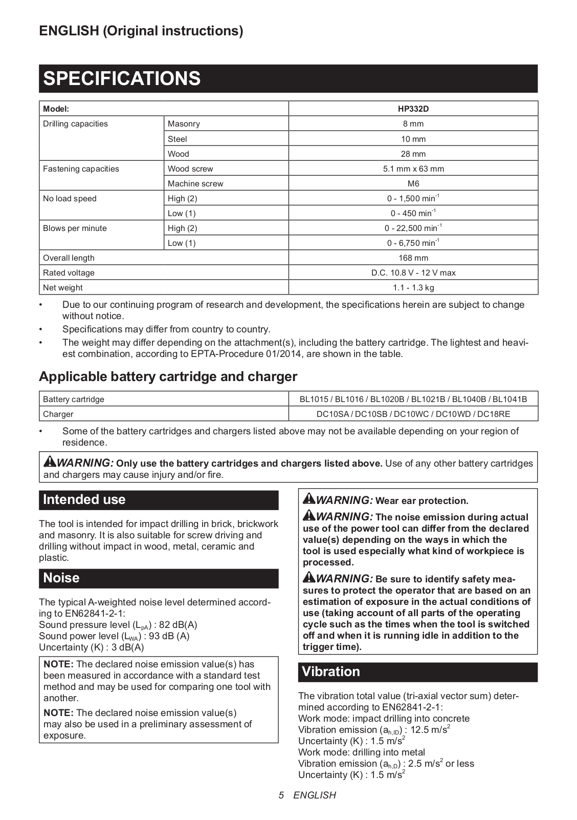
HP332D
5
HP332DSMJ
HP332DWME
HP332DY1J
2
HP332DZ
2
HP333D
2
HP333DSAE
3
HP333DSAX1
HP333DWAE
HP333DZ
6
HP347D
6
HP347DWE
3
HP457D
8
HP457DWE
3
HP457DWE10
2
HP488D002
3
HPR2410
HR
HR002GM204
HR002GZ02
HR003GZ
2
HR004GD201
HR004GM201
HR004GZ
2
HR005GM202
HR005GZ01
2
HR006G
HR006GZ
HR007G
HR008GM203
3
HR008GZ06
4
HR009GM203
3
HR009GZ04
4
HR140D
3
HR140DSAE1
2
HR140DSMJ
4
HR140DWYE1
2
HR140DZ
2
HR160D
7
HR160DH
HR160DWAHR160D
HR160DWH
HR166D
2
HR166DSAE1
2
HR166DSMJ
2
HR166DWAE1
2
HR166DZ
HR 2450 X8
HR 2470 X15
HR 2611FX5
Loading...
Loading...
Nothing found
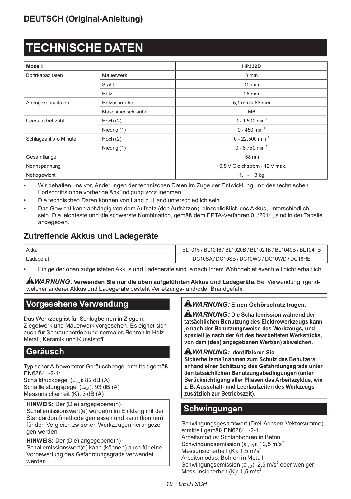
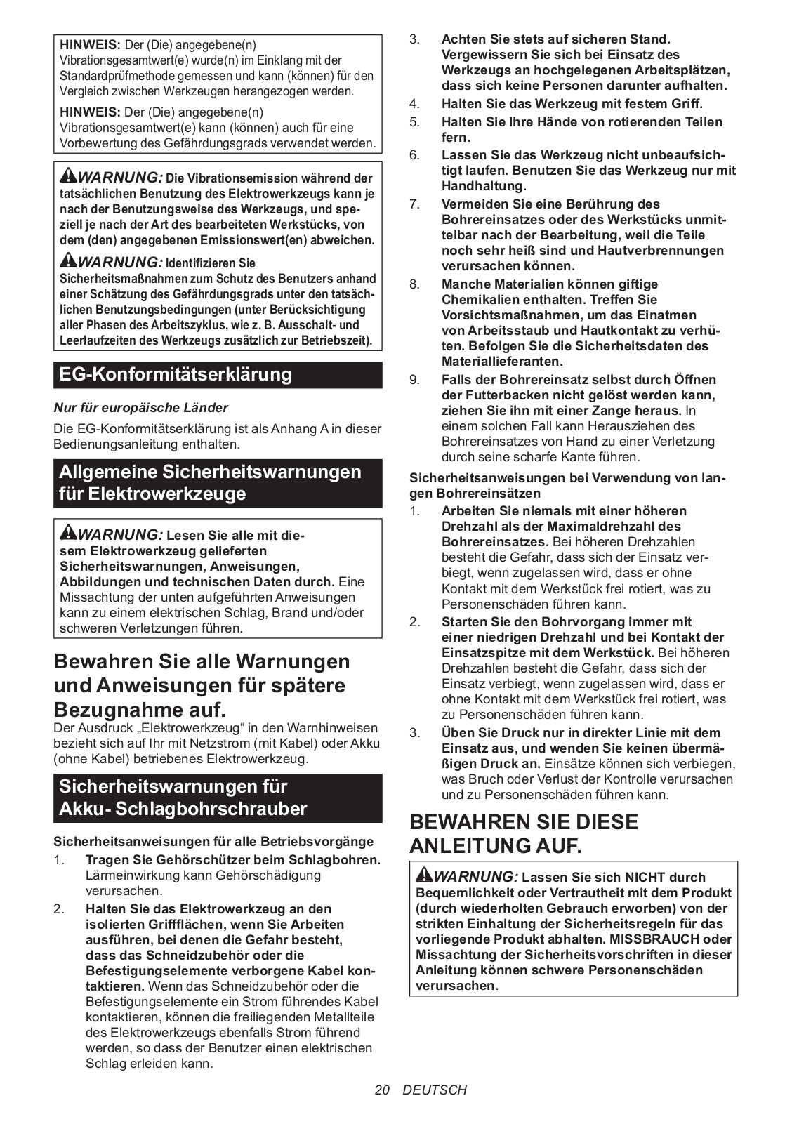
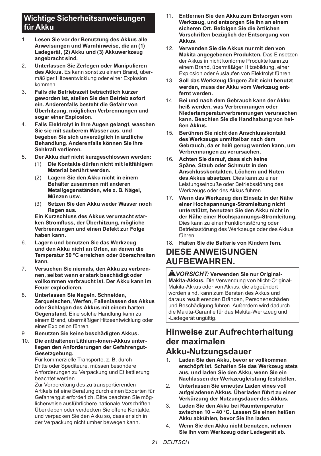
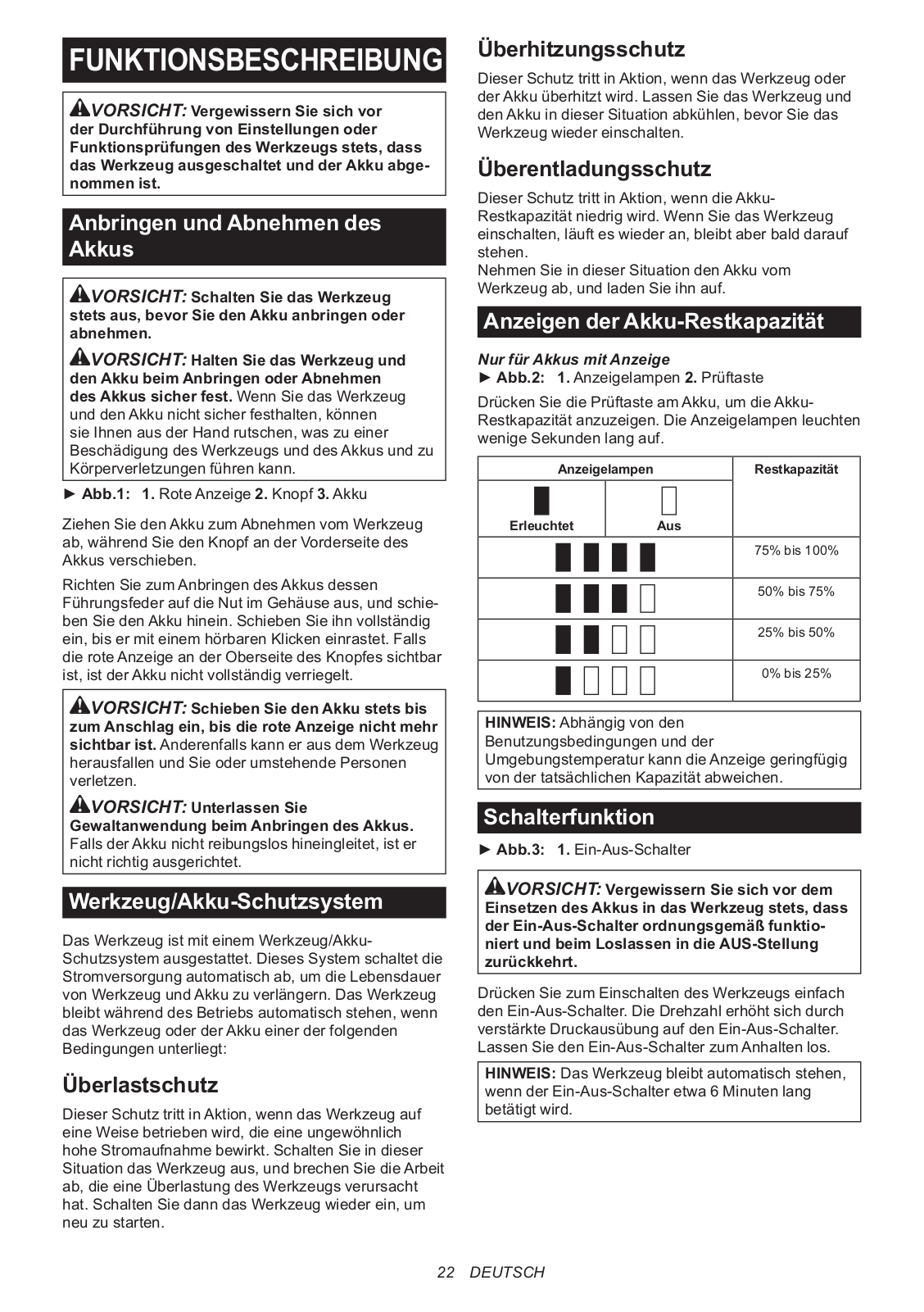
HP332D
Instruction Manual
12 pgs
2.45 Mb
0
Instruction Manual
10 pgs
403.14 Kb
0
Instruction Manual
72 pgs
15.15 Mb
0
Technical Information
20 pgs
30.11 Mb
0
User manual
80 pgs
16.49 Mb
0
Table of contents
Loading...
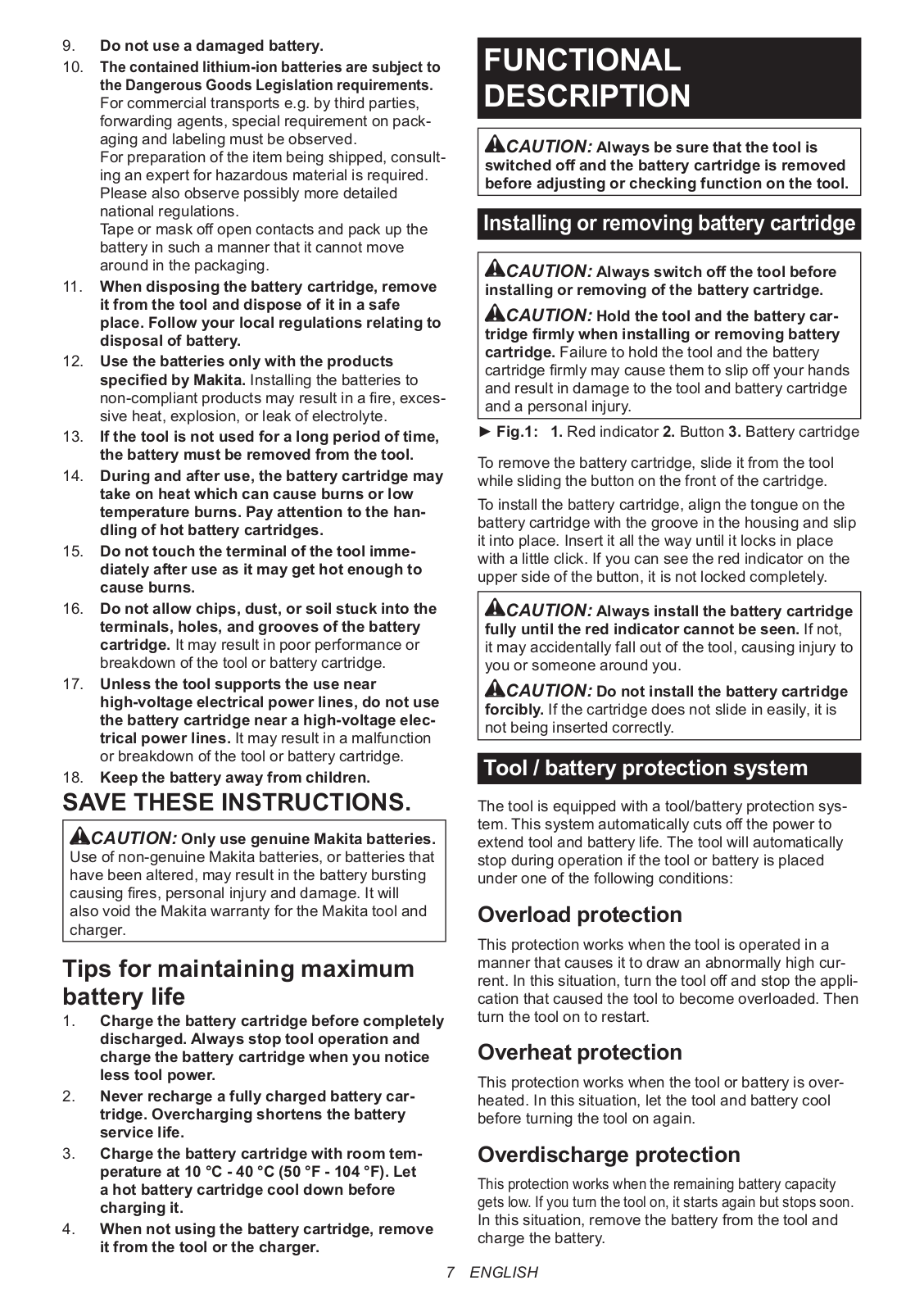
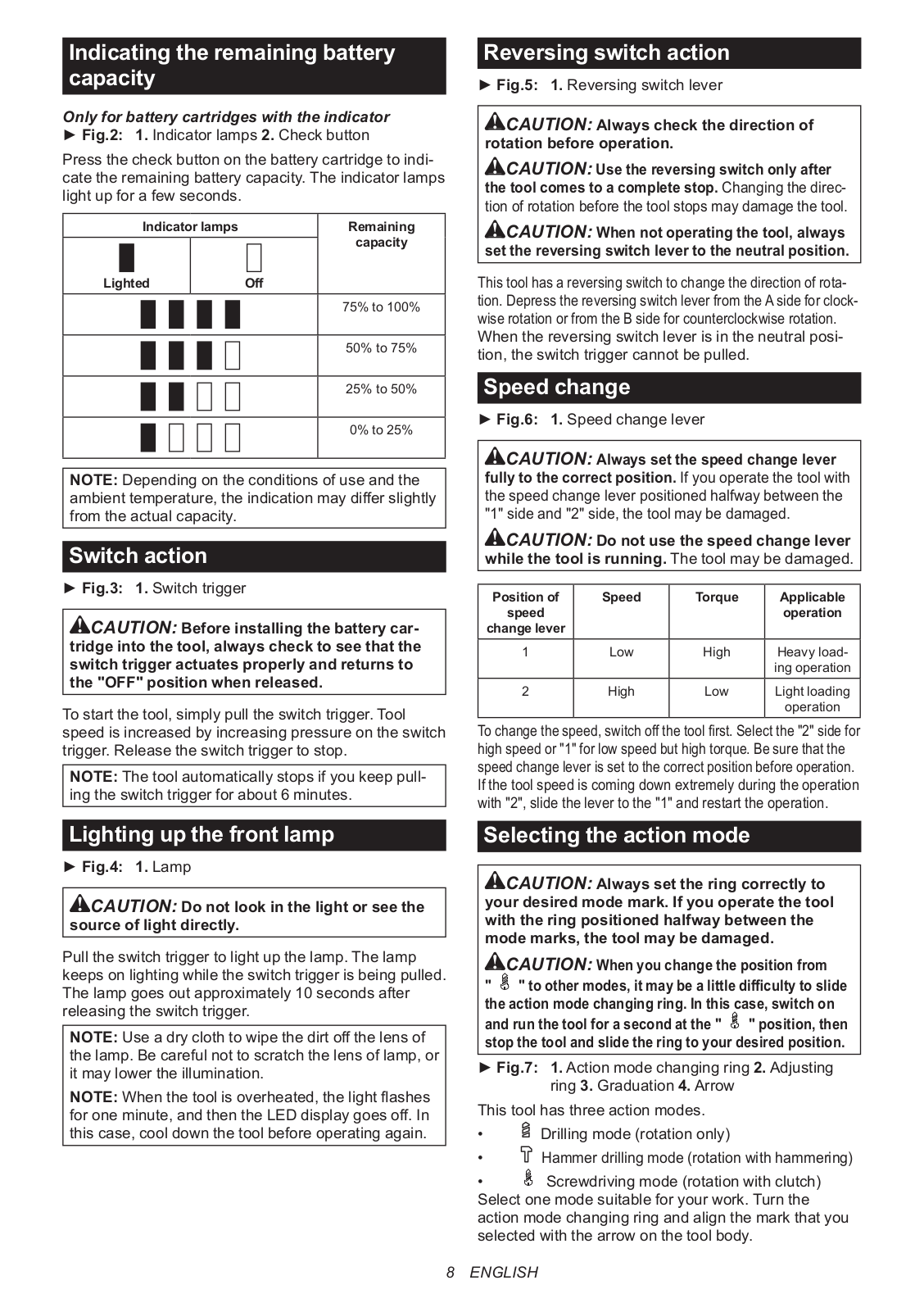
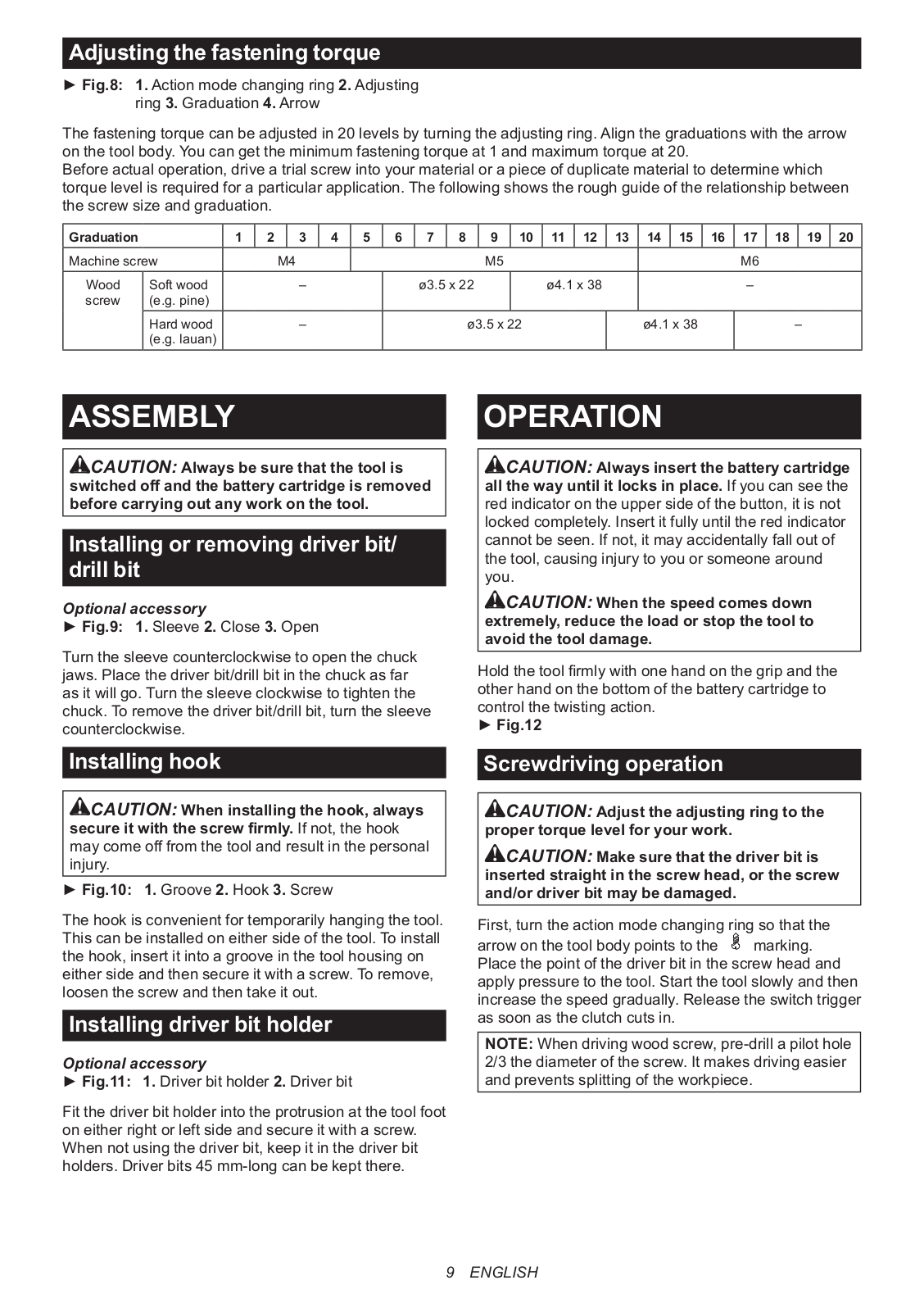
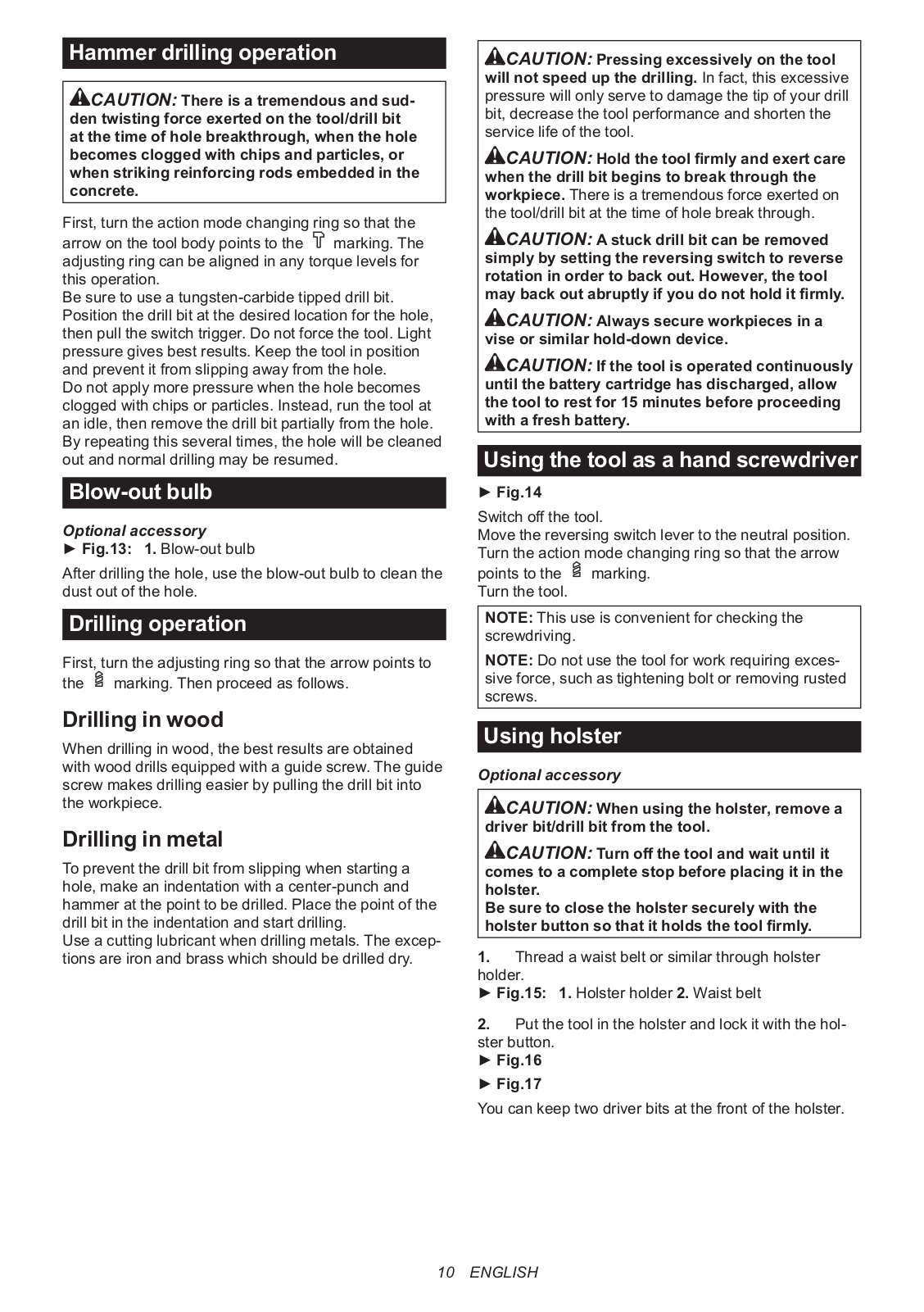
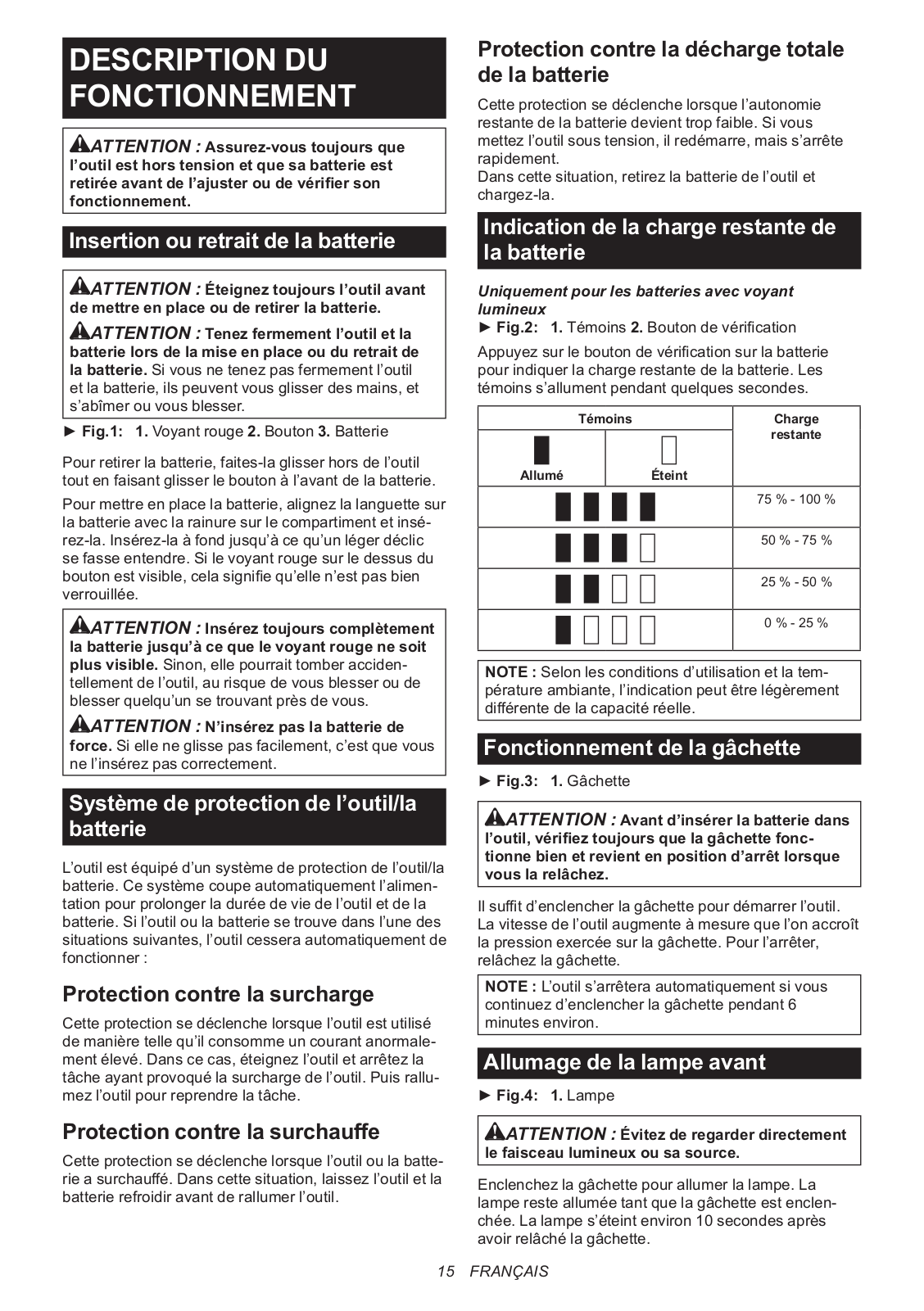
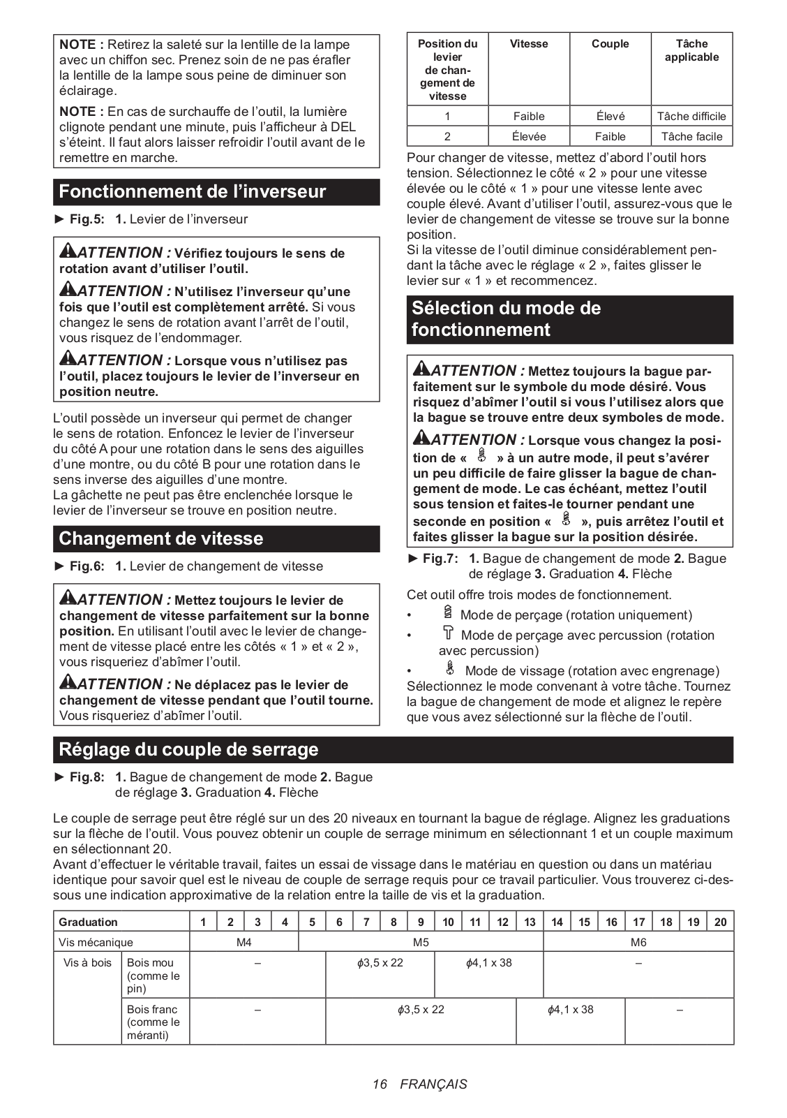
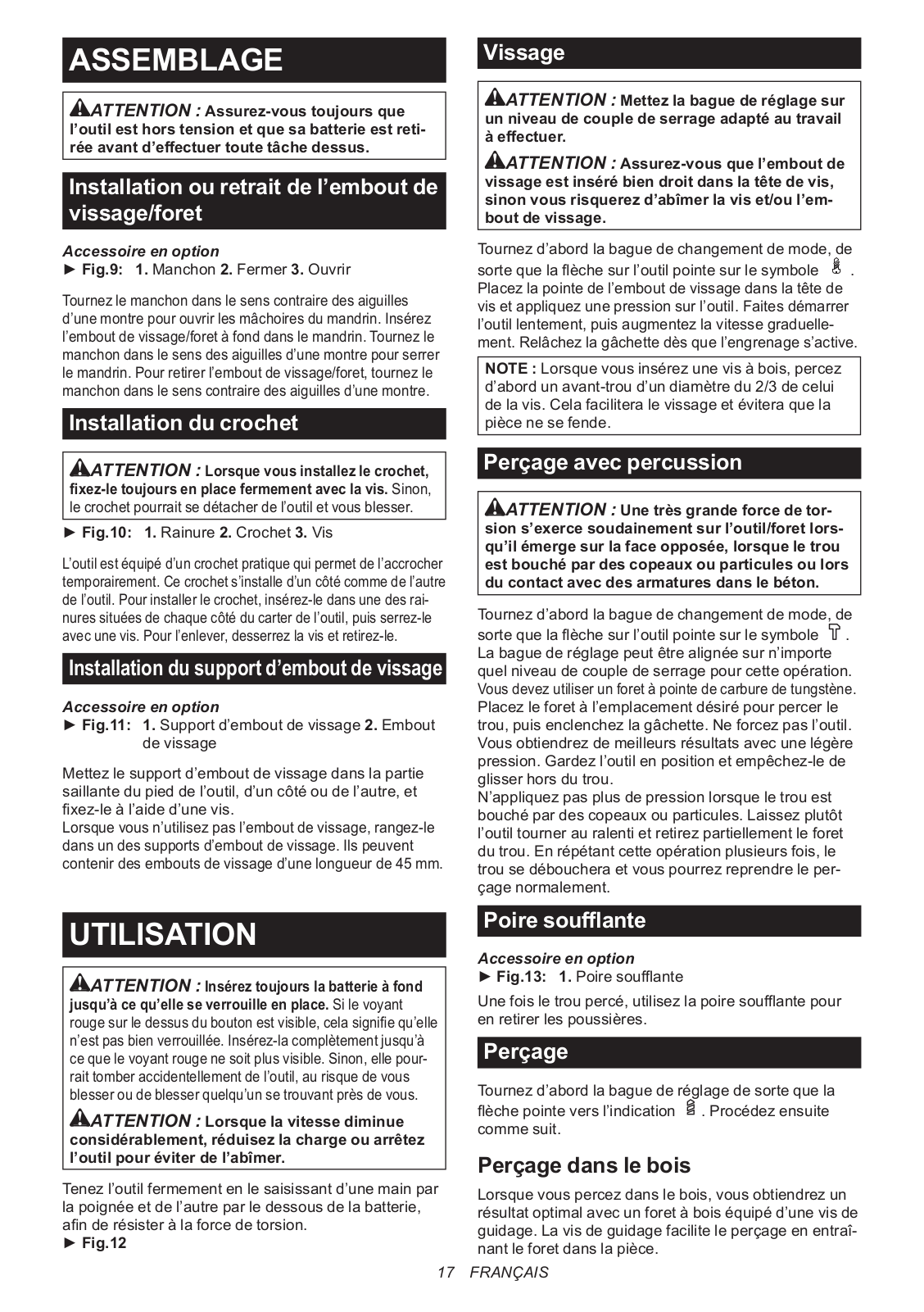
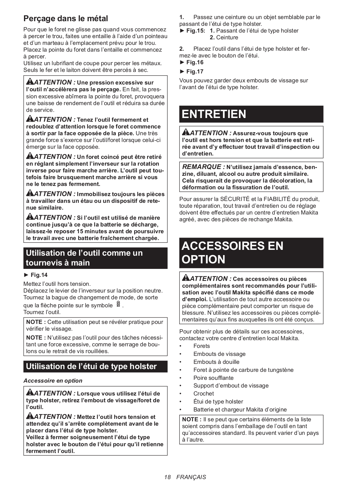
Makita HP332D User manual
...
Makita User manual
Download
Specifications and Main Features
Frequently Asked Questions
User Manual
Download
Loading...
+
hidden pages
Unhide
You need points to download manuals.
1 point = 1 manual.
You can buy points or you can get point for every manual you upload.
Buy points
Upload your manuals
 Loading...