

Page 1
GB Cordless Hammer Driver Drill Instruction manual
Perceuse Percussion-Visseuse
F
sans Fil
D Akku-Bohrhammer Betriebsanleitung
I Trapano avvitatore a batterie Istruzioni per l’uso
con percussione
NL
Accuschroef-boorhamermachine
E Rotomartillo Atornillador Manual de instrucciones
Inalámbrico
P Furadeira de Impacto/ Manual de instruções
Parafusadeira a Bateria
DK Ledningsfri slagboremaskine Brugsanvisning
Manuel d’instructions
Gebruiksaanwijzing
GR Κρουστικό δραπανοκατσάβιδο Οδηγίες χρήσης
μπαταρίας
TR Akülü Darbeli Matkap Tornavida Kullanım kılavuzu
HP330D
012913
Page 2
1 012914 2 012917
1
2
3
4
5
A
B
6
7
8
9
10
8
11
3 012916 4 012918
5 012919 6 012923
7 012920 8 012915
2
Page 3
9 012921 10 002449
12
13
14
11 012922 12 012924
13 012926 14 012968
3
Page 4

ENGLISH (Original instructions)
Explanation of general view
1. Battery cartridge
2. Button
3. Switch trigger
4. Lamp
5. Reversing switch lever
6. Speed change lever
7. Action mode changing ring
8. Arrow
9. Adjusting ring
10. Graduation
11. Sleeve
12. Blow-out bulb
13. Holster holder
14. Waist belt
SPECIFICATIONS
Model HP330D
Concrete 8 mm
Steel 10 mm
Capacities
No load speed (min
Blows per minute (min
• Due to our continuing programme of research and development, the specifications herein are subject to change without
notice.
• Specifications and battery cartridge may differ from country to country.
• Weight, with battery cartridge, according to EPTA-Procedure 01/2003
Intended use
The tool is intended for impact drilling in brick, concrete
and stone. It is also suitable for screw driving and drilling
without impact in wood, metal, ceramic and plastic.
-1
)
-1
)
Overall length 201 mm
Net weight 1.1 kg
Rated voltage D.C. 10.8 V
ENE079-1
General Power Tool Safety
Warnings
WARNING Read all safety warnings and all
instructions. Failure to follow the warnings and
instructions may result in electric shock, fire and/or
serious injury.
GEA010-1
Save all warnings and
instructions for future reference.
CORDLESS HAMMER DRIVER
DRILL SAFETY WARNINGS
1. Wear ear protectors when impact drilling.
Exposure to noise can cause hearing loss.
2. Use auxiliary handle(s), if supplied with the tool.
Loss of control can cause personal injury.
3. Hold power tool by insulated gripping surfaces,
when performing an operation where the cutting
accessory may contact hidden wiring. Cutting
accessory contacting a “live” wire may make exposed
metal parts of the power tool “live” and could give the
operator an electric shock.
4
GEB056-5
Wood 21 mm
Wood screw 5.1 mm x 63 mm
Machine screw M6
High (2) 0 - 1,500
Low (1) 0 - 400
High (2) 0 - 22,500
Low (1) 0 - 6,000
4. Hold power tool by insulated gripping surfaces,
when performing an operation where the fastener
may contact hidden wiring. Fasteners contacting a
“live” wire may make exposed metal parts of the
power tool “live” and could give the operator an
electric shock.
5. Always be sure you have a firm footing.
Be sure no one is below when using the tool in
high locations.
6. Hold the tool firmly.
7. Keep hands away from rotating parts.
8. Do not leave the tool running. Operate the tool
only when hand-held.
9. Do not touch the bit or the workpiece immediately
after operation; they may be extremely hot and
could burn your skin.
10. Some material contains chemicals which may be
toxic. Take caution to prevent dust inhalation and
skin contact. Follow material supplier safety data.
SAVE THESE INSTRUCTIONS.
WARNING:
DO NOT let comfort or familiarity with product (gained
from repeated use) replace strict adherence to safety
rules for the subject product. MISUSE or failure to
follow the safety rules stated in this instruction
manual may cause serious personal injury.
Page 5

IMPORTANT SAFETY
INSTRUCTIONS
ENC009-1
FOR BATTERY CARTRIDGE
1. Before using battery cartridge, read all
instructions and cautionary markings on (1)
battery charger, (2) battery, and (3) product using
battery.
2. Do not disassemble battery cartridge.
3. If operating time has become excessively shorter,
stop operating immediately. It may result in a risk
of overheating, possible burns and even an
explosion.
4. If electrolyte gets into your eyes, rinse them out
with clear water and seek medical attention right
away. It may result in loss of your eyesight.
5. Do not short the battery cartridge:
(1) Do not touch the terminals with any
conductive material.
(2) Avoid storing battery cartridge in a container
with other metal objects such as nails, coins,
etc.
(3) Do not expose battery cartridge to water or
rain.
A battery short can cause a large current flow,
overheating, possible burns and even a
breakdown.
6. Do not store the tool and battery cartridge in
locations where the temperature may reach or
exceed 50°C (122°F).
7. Do not incinerate the battery cartridge even if it is
severely damaged or is completely worn out. The
battery cartridge can explode in a fire.
8. Be careful not to drop or strike battery.
9. Do not use a damaged battery.
SAVE THESE INSTRUCTIONS.
Tips for maintaining maximum battery life
1. Charge the battery cartridge before completely
discharged.
Always stop tool operation and charge the battery
cartridge when you notice less tool power.
2. Never recharge a fully charged battery cartridge.
Overcharging shortens the battery service life.
3. Charge the battery cartridge with room
temperature at 10°C - 40°C (50°F - 104°F). Let a hot
battery cartridge cool down before charging it.
FUNCTIONAL DESCRIPTION
CAUTION:
• Always be sure that the tool is switched off and the
battery cartridge is removed before adjusting or
checking function on the tool.
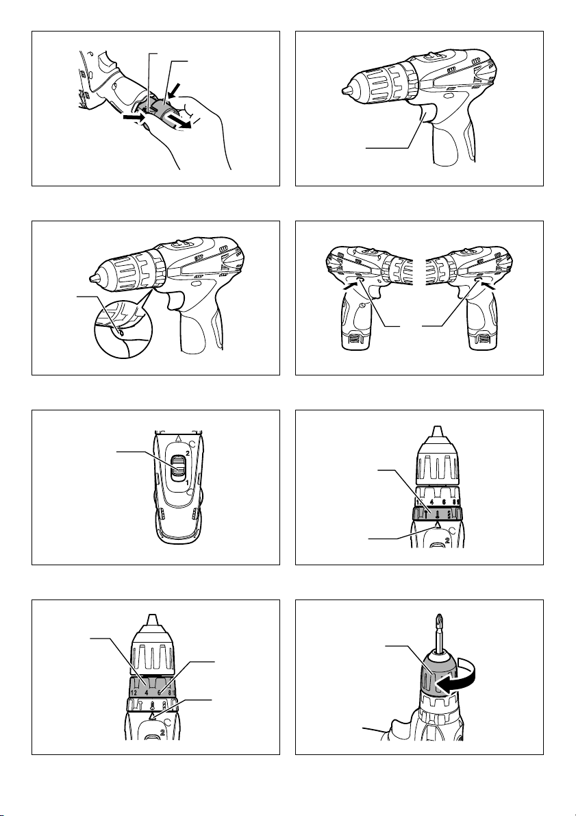
Installing or removing battery cartridge
(Fig. 1)
CAUTION:
• Always switch off the tool before installing or removing
of the battery cartridge.
• Hold the tool and the battery cartridge firmly when
installing or removing battery cartridge. Failure to
hold the tool and the battery cartridge firmly may cause
them to slip off your hands and result in damage to the
tool and battery cartridge and a personal injury.
To remove the battery cartridge, withdraw it from the tool
while pressing the buttons on both sides of the cartridge.
To install the battery cartridge, hold it so that the battery
cartridge front shape fits to that of the battery installment
opening and slip it into place. Insert it all the way until it
locks in place with a little click.
CAUTION:
• Always insert the battery cartridge all the way until it
locks in place. If not, it may accidentally fall out of the
tool, causing injury to you or someone around you.
• Do not install the battery cartridge forcibly. If the
cartridge does not slide in easily, it is not being inserted
correctly.
Battery protection system
The tool is equipped with a battery protection system. This
system automatically cuts off power to the motor to extend
battery life.
The tool will automatically stop during operation if the tool
and/or battery are placed under one of the following
conditions:
• Overloaded:
The tool is operated in a manner that causes it to
draw an abnormally high current.
In this situation, release the switch trigger on the tool
and stop the application that caused the tool to
become overloaded. Then pull the switch trigger
again to restart.
• Low battery voltage:
The remaining battery capacity is too low and the tool
will not operate. If you pull the switch trigger, the
motor runs again but stops soon. In this situation,
remove and recharge the battery.
Switch action (Fig. 2)
CAUTION:
• Before inserting the battery cartridge into the tool,
always check to see that the switch trigger actuates
properly and returns to the “OFF” position when
released.
To start the tool, simply pull the switch trigger. Tool speed
is increased by increasing pressure on the switch trigger.
Release the switch trigger to stop.
Turning on the front lamp (Fig. 3)
CAUTION:
• Do not look in the light or see the source of the light
directly.
Pull the switch trigger to turn on the light. The lamp keeps
on lighting while the switch trigger is being pulled. The
lamp turns off just after releasing the trigger.
NOTE:
• Use a dry cloth to wipe the dirt off the lens of lamp. Be
careful not to scratch the lens of lamp, or it may lower
the illumination.
5
Page 6

Reversing switch action (Fig. 4)
This tool has a reversing switch to change the direction of
rotation. Depress the reversing switch lever from the A
side for clockwise rotation or from the B side for
counterclockwise rotation.
When the reversing switch lever is in the neutral position,
the switch trigger cannot be pulled.
CAUTION:
• Always check the direction of rotation before operation.
• Use the reversing switch only after the tool comes to a
complete stop. Changing the direction of rotation
before the tool stops may damage the tool.
• When not operating the tool, always set the reversing
switch lever to the neutral position.
Speed change (Fig. 5)
To change the speed, first switch off the tool and then
slide the speed change lever to the “2” side for high speed
or “1” side for low speed. Be sure that the speed change
lever is set to the correct position before operation. Use
the right speed for your job.
CAUTION:
• Always set the speed change lever fully to the correct
position. If you operate the tool with the speed change
lever positioned halfway between the “1” side and “2”
side, the tool may be damaged.
• Do not use the speed change lever while the tool is
running. The tool may be damaged.
Selecting the action mode (Fig. 6)
This tool employs an action mode changing ring. Select
one of the three modes suitable for your work needs by
using this ring.
For rotation only, turn the ring so that the arrow on the tool
body points toward the mark on the ring.
For rotation with hammering, turn the ring so that the
arrow points toward the mark on the ring.
For rotation with clutch, turn the ring so that the arrow
points toward the mark on the ring.
CAUTION:
• When you change the position from “ ” to other
modes, it may be a little difficulty to slide the action
mode changing ring. In this case, switch on and run the
tool for a second at the “ ” position, then stop the tool
and slide the ring to your desired position.
• Always set the ring correctly to your desired mode
mark. If you operate the tool with the ring positioned
halfway between the mode marks, the tool may be
damaged.
Adjusting the fastening torque (Fig. 7)
The fastening torque can be adjusted in 18 steps by
turning the adjusting ring so that the graduations are
aligned with the arrow on the tool body. The fastening
torque is minimum when the number 1 is aligned with the
arrow, and maximum when the number 18 is aligned with
the arrow.
Before the actual operation, drive a trial screw into your
material or a piece of duplicate material to determine
which torque level is required for a particular application.
NOTE:
• The fastening torque can be adjusted only when the
arrow points toward the mark on the ring.
ASSEMBLY
CAUTION:
• Always be sure that the tool is switched off and the
battery cartridge is removed before carrying out any
work on the tool.
Installing or removing driver bit or drill bit
(Fig. 8)
Turn the sleeve counterclockwise to open the chuck jaws.
Place the bit in the chuck as far as it will go. Turn the
sleeve clockwise to tighten the chuck.
To remove the bit, turn the sleeve counterclockwise.
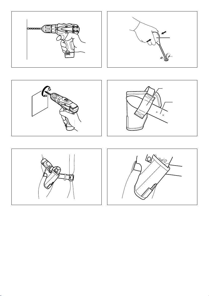
OPERATION (Fig. 9)
CAUTION:
• Always insert the battery cartridge all the way until it
locks in place. Otherwise, it may accidentally fall out of
the tool, causing injury to you or someone around you.
Hold the tool firmly with one hand on the grip and the
other hand on the bottom of the battery cartridge to
control the twisting action.
CAUTION:
• Do not cover vents, or it may cause overheating and
damage to the tool.
Hammer drilling operation
CAUTION:
• There is a tremendous and sudden twisting force
exerted on the tool/bit at the time of hole breakthrough, when the hole becomes clogged with chips
and particles, or when striking reinforcing rods
embedded in the concrete.
First, turn the action mode changing ring so that the arrow
on the tool body points to the marking. The adjusting
ring can be aligned in any torque levels for this operation.
Be sure to use a tungsten-carbide tipped bit.
Position the bit at the desired location for the hole, then
pull the switch trigger. Do not force the tool. Light
pressure gives best results. Keep the tool in position and
prevent it from slipping away from the hole.
Do not apply more pressure when the hole becomes
clogged with chips or particles. Instead, run the tool at an
idle, then remove the bit partially from the hole. By
repeating this several times, the hole will be cleaned out
and normal drilling may be resumed.
Blow-out bulb (optional accessory)
(Fig. 10)
After drilling the hole, use the blow-out bulb to clean the
dust out of the hole.
Drilling operation
First, turn the adjusting ring so that the pointer points to
the marking. Then proceed as follows.
6
Page 7

CAUTION:
• Pressing excessively on the tool will not speed up the
drilling. In fact, this excessive pressure will only serve
to damage the tip of your bit, decrease the tool
performance and shorten the service life of the tool.
• There is a tremendous force exerted on the tool/bit at
the time of hole break through. Hold the tool firmly and
exert care when the bit begins to break through the
workpiece.
• A stuck bit can be removed simply by setting the
reversing switch to reverse rotation in order to back
out. However, the tool may back out abruptly if you do
not hold it firmly.
• Always secure small workpieces in a vise or with a
similar hold-down device.
• If the tool is operated continuously until the battery
cartridge has discharged, allow the tool to rest for
15 minutes before proceeding with a fresh battery.
• Do not pull the switch trigger repeatedly when the
motor is locked. It may damage the tool.
Drilling in wood
When drilling in wood, the best results are obtained with
wood drills equipped with a guide screw. The guide screw
makes drilling easier by pulling the bit into the workpiece.
Drilling in metal
To prevent the bit from slipping when starting to make a
hole, make an indentation with a center-punch and
hammer at the point to be drilled. Place the point of the bit
in the indentation and start drilling.
Use a cutting lubricant when drilling metals. The
exceptions are iron and brass which should be drilled dry.
Screwdriving operation
First, turn the action mode changing ring so that the arrow
on the tool body points to the marking. Adjust the
adjusting ring to the proper torque level for your work.
Then proceed as follows.
Place the point of the driver bit in the screw head and
apply pressure to the tool. Start the tool slowly and then
increase the speed gradually. Release the switch trigger
as soon as the clutch cuts in.
CAUTION:
• Make sure that the driver bit is inserted straight in the
screw head, or the screw and/or bit may be damaged.
NOTE:
• When driving wood screw, predrill a pilot hole 2/3 the
diameter of the screw. It makes driving easier and
prevents splitting of the workpiece.
Using the tool as a hand screwdriver
(Fig. 11)
Switch off the tool.
Move the reversing switch lever to the neutral position.
Turn the tool.
NOTE:
• This use is convenient for checking the screwdriving.
• Do not use the tool for work requiring excessive force,
such as tightening bolt or removing rusted screws.
Using holster (Optional accessory)
CAUTION:
• Do not use for tools such as a drill with a bit installed on
them.
• Turn off the tool and wait until it comes to a complete
stop before placing it in the holster.
Be sure to close the holster securely so that it holds the
tool firmly. (Fig. 12)
Thread a waist belt or similar through holster holder.
(Fig. 13)
Put the tool in the holster and lock it with the holster
button. (Fig. 14)
You can keep two bits at the front of holster.
MAINTENANCE
CAUTION:
• Always be sure that the tool is switched off and the
battery cartridge is removed before performing any
inspection or maintenance.
• Never use gasoline, benzine, thinner, alcohol or the
like. Discoloration, deformation or cracks may result.
To maintain product SAFETY and RELIABILITY, repairs,
any other maintenance or adjustment should be
performed by Makita Authorized Service Centers, always
using Makita replacement parts.
OPTIONAL ACCESSORIES
CAUTION:
• These accessories or attachments are recommended
for use with your Makita tool specified in this manual.
The use of any other accessories or attachments might
present a risk of injury to persons. Only use accessory
or attachment for its stated purpose.
If you need any assistance for more details regarding
these accessories, ask your local Makita Service Center.
• Drill bits
• Tungsten-carbide tipped hammer bit
• Screw bits
• Socket bits
• Makita genuine battery and charger
• Blow-out bulb
• Safety goggles
•Holster
• Plastic carrying case
NOTE:
• Some items in the list may be included in the tool
package as standard accessories. They may differ
from country to country.
Noise
The typical A-weighted noise level determined according
to EN60745:
Sound pressure level (L
Sound power level (L
Uncertainty (K): 3 dB (A)
Wear ear protection
): 82 dB (A)
pA
): 93 dB (A)
WA
ENG905-1
7
Page 8

Vibration
ENG900-1
The vibration total value (tri-axial vector sum) determined
according to EN60745:
Work mode: impact drilling into concrete
Vibration emission (a
Uncertainty (K): 1.5 m/s
h,ID
): 9.5 m/s
2
2
Work mode: drilling into metal
Vibration emission (a
Uncertainty (K): 1.5 m/s
): 2.5 m/s2 or less
h,D
2
ENG901-1
• The declared vibration emission value has been
measured in accordance with the standard test method
and may be used for comparing one tool with another.
• The declared vibration emission value may also be
used in a preliminary assessment of exposure.
WARNING:
• The vibration emission during actual use of the power
tool can differ from the declared emission value
depending on the ways in which the tool is used.
• Be sure to identify safety measures to protect the
operator that are based on an estimation of exposure in
the actual conditions of use (taking account of all parts
of the operating cycle such as the times when the tool
is switched off and when it is running idle in addition to
the trigger time).
For European countries only
ENH101-15
EC Declaration of Conformity
We Makita Corporation as the responsible
manufacturer declare that the following Makita
machine(s):
Designation of Machine:
Cordless Hammer Driver Drill
Model No./Type: HP330D
are of series production and
Conforms to the following European Directives:
2006/42/EC
And are manufactured in accordance with the following
standards or standardised documents:
EN60745
The technical documentation is kept by our authorised
representative in Europe who is:
Makita International Europe Ltd.
Michigan Drive, Tongwell,
Milton Keynes, Bucks MK15 8JD, England
13. 10. 2011
Tomoyasu Kato
Director
Makita Corporation
3-11-8, Sumiyoshi-cho,
Anjo, Aichi, 446-8502, JAPAN
8
Page 9

NEDERLANDS (Originele instructies)
Verklaring van het onderdelenoverzicht
1. Accu
2. Knop
3. Aan/uit-schakelaar
4. Lampje
5. Omkeerschakelaar
6. Snelheidsinstelknop
7. Werkingsfunctie-keuzering
8. Pijlpunt
9. Instelring
10. Schaalverdeling
11. M of
12. Blaasbalgje
13. Holsterhouder
14. Broekriem
TECHNISCHE GEGEVENS
Model HP330D
Beton 8 mm
Staal 10 mm
Vermogen
Nullasttoerental (min
Aantal slagen (min
• Als gevolg van ons doorlopende onderzoeks- en ontwikkelingsprogramma, zijn de technische gegevens van dit
gereedschap onderhevig aan veranderingen zonder voorafgaande kennisgeving.
• Specificaties en accu’s kunnen van land tot land verschillen.
• Gewicht, inclusief de accu, volgens de EPTA-procedure 01/2003
Gebruiksdoeleinden
Het gereedschap is bedoeld voor slagboren en boren in
baksteen, beton en steen. Het is ook geschikt voor
schroeven draaien en boren zonder slagwerking in hout,
metaal, keramisch materiaal en kunststof.
-1
)
-1
)
Totale lengte 201 mm
Nettogewicht 1,1 kg
Nominale spanning 10,8 V gelijkstroom
ENE079-1
Algemene
veiligheidswaarschuwingen voor
elektrisch gereedschap
WAARSCHUWING Lees alle
veiligheidswaarschuwingen en alle instructies. Het
niet volgen van de waarschuwingen en instructies kan
leiden tot elektrische schokken, brand en/of ernstig letsel.
GEA010-1
Bewaar alle waarschuwingen en
instructies om in de toekomst te
kunnen raadplegen.
VEILIGHEIDSWAARSCHUWINGEN
SPECIFIEK VOOR EEN
ACCUSCHROEFBOORHAMERMACHINE
1. Draag gehoorbescherming tijdens het slagboren.
Blootstelling aan harde geluiden kan leiden tot
gehoorbeschadiging.
GEB056-5
Hout 21 mm
Houtschroef 5,1 mm x 63 mm
Machineschroef M6
Hoog (2) 0 - 1.500
Laag (1) 0 - 400
Hoog (2) 0 - 22.500
Laag (1) 0 - 6.000
2. Gebruik de hulphandgrepen, als deze bij het
gereedschap werden geleverd. Als u de controle
over het gereedschap verliest, kan dit leiden tot
persoonlijk letsel.
3. Houd het elektrisch gereedschap vast aan het
geïsoleerde oppervlak van de handgrepen
wanneer u werkt op plaatsen waar het
booraccessoire met verborgen bedrading in
aanraking kan komen. Wanneer het accessoire in
aanraking komen met onder spanning staande
draden, zullen de niet-geïsoleerde metalen delen van
het gereedschap onder spanning komen te staan
zodat de gebruiker een elektrische schok kan krijgen.
4. Houd het elektrisch gereedschap vast aan het
geïsoleerde oppervlak van de handgrepen
wanneer u werkt op plaatsen waar het
bevestigingsmateriaal met verborgen bedrading in
aanraking kan komen. Wanneer
bevestigingsmaterialen in aanraking komen met onder
spanning staande draden, zullen de niet-geïsoleerde
metalen delen van het gereedschap onder spanning
komen te staan zodat de gebruiker een elektrische
schok kan krijgen.
5. Zorg er altijd voor dat u stevig staat.
Zorg ervoor dat er niemand zich onder u bevindt
wanneer u het gereedschap op een hoge plaats
gebruikt.
6. Houd het gereedschap stevig vast.
7. Houd uw handen uit de buurt van draaiende delen.
26
Page 10

8. Laat het gereedschap niet ingeschakeld liggen.
Bedien het gereedschap alleen wanneer u het
vasthoudt.
9. Raak de boor/het bit en het werkstuk niet
onmiddellijk na gebruik aan. Zij kunnen bijzonder
heet zijn en brandwonden op uw huid
veroorzaken.
10. Sommige materialen bevatten chemische stoffen
die giftig kunnen zijn. Neem
voorzorgsmaatregelen tegen het inademen van
stof en contact met de huid. Volg de
veiligheidsinstructies van de leverancier van het
materiaal op.
BEWAAR DEZE INSTRUCTIES
WAARSCHUWING:
Laat u NIET misleiden door een vals gevoel van
comfort en bekendheid met het gereedschap (na
veelvuldig gebruik) en neem alle
veiligheidsvoorschriften van het betreffende product
altijd strikt in acht. VERKEERD GEBRUIK of het niet
volgen van de veiligheidsinstructies in deze
gebruiksaanwijzing kan leiden tot ernstig persoonlijk
letsel.
BELANGRIJKE
VEILIGHEIDSINSTRUCTIES ENC009-1
VOOR ACCU’S
1. Alvorens de accu in gebruik te nemen, leest u
eerst alle instructies en
waarschuwingsopschriften op (1) de acculader, (2)
de accu en (3) het apparaat waarin de accu wordt
aangebracht.
2. Haal de accu niet uit elkaar.
3. Als de gebruikstijd aanzienlijk korter is geworden,
stopt u onmiddellijk met het gebruik. Anders kan
dit leiden tot kans op oververhitting, mogelijke
brandwonden en zelfs een explosie.
4. Als de elektrolyt in uw ogen komt, wast u deze uit
met schoon water en raadpleegt u onmiddellijk
een arts. Dit kan leiden tot verlies van
gezichtsvermogen.
5. Sluit de accu niet kort:
(1) Raak de accupolen niet aan met enig geleidend
materiaal.
(2) Bewaar de accu niet op een plaats waar deze in
aanraking kan komen met andere metalen
voorwerpen, zoals spijkers, munten, enz.
(3) Stel de accu niet bloot aan water of regen.
Kortsluiting van de accu kan leiden tot een hoge
stroomsterkte, oververhitting, mogelijke
brandwonden en zelfs een defect.
6. Bewaar het gereedschap en de accu niet op
plaatsen waar de temperatuur kan oplopen tot
50 °C of hoger.
7. Werp de accu niet in een vuur, zelfs niet als deze
al ernstig beschadigd of helemaal versleten is. De
accu kan in een vuur exploderen.
8. Wees voorzichtig dat u de accu niet laat vallen of
ergens tegenaan stoot.
9. Gebruik nooit een beschadigde accu.
BEWAAR DEZE INSTRUCTIES
Tips voor een lange levensduur van de
accu
1. Laad de accu op voordat deze volledig leeg is.
Wanneer u merkt dat het gereedschap minder
vermogen heeft, stopt u met het gebruik ervan en
laadt u eerst de accu op.
2. Laad nooit een volledig opgeladen accu op.
Te lang opladen verkort de levensduur van de
accu.
3. Laad de accu op bij een omgevingstemperatuur
van 10 °C tot 40 °C. Laat een warme accu eerst
afkoelen voordat u deze oplaadt.
BESCHRIJVING VAN DE
FUNCTIES
LET OP:
• Zorg ervoor dat het gereedschap is uitgeschakeld en
dat de accu is verwijderd voordat u de werking van het
gereedschap aanpast of controleert.
De accu aanbrengen en verwijderen (zie
afb. 1)
LET OP:
• Schakel het gereedschap altijd uit voordat u de accu
aanbrengt of verwijdert.
• Houd het gereedschap en de accu stevig vast
tijdens het aanbrengen of verwijderen van de accu.
Als u het gereedschap en de accu niet stevig
vasthoudt, kunnen deze uit uw handen glippen en
beschadigd raken, of kan persoonlijk letsel worden
veroorzaakt.
Om de accu te verwijderen, drukt u de knoppen aan beide
zijkanten van de accu in en trekt u tegelijkertijd de accu
van het gereedschap af.
Om de accu aan te brengen, houdt u de accu zodanig
vast dat de vorm aan de voorkant van de accu past in de
accuplaatsingsopening, en schuift u de accu op zijn
plaats. Steek de accu zo ver mogelijk erin tot u een
klikgeluid hoort.
LET OP:
• Steek de accu altijd zo ver mogelijk in het gereedschap
totdat deze met een klik wordt vergrendeld. Als u dit
niet doet, kan de accu per ongeluk uit het gereedschap
vallen en u of anderen in uw omgeving verwonden.
• Breng de accu niet met kracht aan. Als de accu niet
gemakkelijk erin kan worden geschoven, wordt deze
niet goed aangebracht.
Accubeveiligingssysteem
Het gereedschap is uitgerust met een
accubeveiligingssysteem. Dit systeem schakelt
automatisch de voeding naar de motor uit om de
levensduur van de accu te verlengen.
Het gereedschap zal tijdens gebruik automatisch stoppen
wanneer het gereedschap en/of de accu zich in een van
de volgende omstandigheden bevinden:
27
Page 11

• Overbelasting:
Het gereedschap wordt gebruikt op een manier die
ertoe leidt dat een abnormaal hoge stroomsterkte uit
de accu wordt getrokken.
Laat in die situatie de aan/uit-schakelaar van het
gereedschap los en stop het gebruik dat ertoe leidde
dat het gereedschap overbelast werd. Knijp daarna
opnieuw de aan/uit-schakelaar in om het
gereedschap weer in te schakelen.
• Lage accuspanning:
De resterende acculading is te laag en het
gereedschap wordt niet ingeschakeld. Als u de aan/
uit-schakelaar inknijpt, zal de motor weer gaan
draaien, maar spoedig stoppen. Verwijder in die
situatie de accu en laad hem op.
Aan/uit-schakelaars (zie afb. 2)
LET OP:
• Controleer altijd, voordat u de accu in het gereedschap
steekt, of de aan/uit-schakelaar op de juiste manier
schakelt en weer terugkeert naar de uit-stand nadat
deze is losgelaten.
Om het gereedschap in te schakelen, knijpt u gewoon de
aan/uit-schakelaar in. De draaisnelheid van het
gereedschap neemt toe naarmate u meer druk uitoefent
op de aan/uit-schakelaar. Laat de aan/uit-schakelaar los
om het gereedschap te stoppen.
De lamp op de voorkant inschakelen (zie
afb. 3)
LET OP:
• Kijk niet rechtstreeks in het licht of naar de bron van de
lamp.
Knijp de aan/uit-schakelaar in om de lamp op de voorkant
in te schakelen. De lamp blijft branden zolang u de aan/
uit-schakelaar ingeknepen houdt. De lamp gaat vlak
nadat u de aan/uit-schakelaar hebt losgelaten uit.
OPMERKING:
• Gebruik een doek om het vuil van de lens van de lamp
te vegen. Wees voorzichtig de lens van de lamp niet te
bekrassen om de lichtopbrengst niet te verlagen.
Werking van de omkeerschakelaar (zie
afb. 4)
Dit gereedschap is uitgerust met een omkeerschakelaar
waarmee u de draairichting kunt omkeren. Druk op de
omkeerschakelaar vanaf kant A voor de draairichting
rechtsom, of vanaf kant B voor de draairichting linksom.
Wanneer de omkeerschakelaar in de middenstand staat,
kunt u de aan/uit-schakelaar niet inknijpen.
LET OP:
• Controleer altijd de draairichting alvorens het
gereedschap te gebruiken.
• Gebruik de omkeerschakelaar alleen nadat het
gereedschap volledig tot stilstand is gekomen. Als u de
draairichting verandert voordat het gereedschap
volledig stilstaat, kan het gereedschap worden
beschadigd.
• Als u het gereedschap niet gebruikt, zet u de
omkeerschakelaar altijd in de middenstand.
De snelheid veranderen (zie afb. 5)
Om de draaisnelheid van het gereedschap te veranderen,
schakelt u eerst het gereedschap uit en verschuift u
daarna de snelheidsinstelknop naar stand “2” voor een
hoge draaisnelheid, of naar stand “1” voor een lage
draaisnelheid. Zorg ervoor dat de snelheidsinstelknop in
de juiste stand staat alvorens het gereedschap te
bedienen. Gebruik de juiste draaisnelheid voor uw klus.
LET OP:
• Zet de snelheidsinstelknop altijd volledig in de
gewenste stand. Als u het gereedschap bedient terwijl
de snelheidsinstelknop halverwege de standen “1” en
“2” staat, kan het gereedschap worden beschadigd.
• Bedien de snelheidsinstelknop niet terwijl het
gereedschap draait. Het gereedschap kan hierdoor
worden beschadigd.
De werkingsfunctie kiezen (zie afb. 6)
Dit gereedschap is uitgerust met een werkingsfunctiekeuzering. Kies met deze keuzering uit de drie
beschikbare werkingsfuncties degene die het meest
geschikt is voor uw klus.
Voor alleen ronddraaien, draait u de keuzering zodat de
pijlpunt op het gereedschap naar het symbool op de
ring wijst.
Voor ronddraaien met slagwerking, draait u de keuzering
zodat de pijlpunt op het gereedschap naar het symbool
op de ring wijst.
Voor ronddraaien met slipkoppeling, draait u de keuzering
zodat de pijlpunt op het gereedschap naar het symbool
op de ring wijst.
LET OP:
• Wanneer u de stand verandert van “ ” naar een
andere functie, kan het een enigszins moeilijk zijn de
werkingsfunctie-keuzering te verschuiven. Als dat het
geval is, verschuift u de werkingsfunctie-instelknop
naar de stand “ ” en schakelt u het gereedschap
eventjes in. Schakel vervolgens het gereedschap uit en
verschuif de werkingsfunctie-instelknop naar de
gewenste stand.
• Stel de keuzering altijd in op het symbool van de juiste
stand voor uw klus. Als u het gereedschap bedient met
de keuzering ingesteld tussen twee symbolen in, kan
het gereedschap worden beschadigd.
Het draaikoppel instellen (zie afb. 7)
Het draaikoppel kan in 18 stappen worden ingesteld door
de instelring te draaien zodat de gewenste stand op de
schaalverdeling is uitgelijnd met de pijlpunt op de
behuizing van het gereedschap. Het draaikoppel is
minimaal wanneer stand 1 is uitgelijnd met de pijlpunt, en
maximaal wanneer stand 18 is uitgelijnd met de pijlpunt.
Bepaal het juiste draaikoppelniveau door bij wijze van
proef een schroef in het materiaal of een stuk
gelijkwaardig materiaal te draaien, alvorens het
gereedschap voor de daadwerkelijke klus te gebruiken.
OPMERKING:
• Het draaikoppel kan alleen worden ingesteld wanneer
de pijlpunt naar het symbool op de ring wijst.
28
Page 12

ONDERDELEN AANBRENGEN/
VERWIJDEREN
LET OP:
• Controleer altijd of het gereedschap is uitgeschakeld
en de accu is verwijderd alvorens enige
werkzaamheden aan het gereedschap te verrichten.
Het schroefbit of boorbit aanbrengen en
verwijderen (zie afb. 8)
Draai de mof linksom om de klauwen in de spankop te
openen. Steek de boor/het bit zo ver mogelijk in de
spankop. Draai de mof rechtsom om de spankop te
sluiten.
Om de boor/het bit te verwijderen, draait u de mof
linksom.
BEDIENING (zie afb. 9)
LET OP:
• Steek de accu altijd zo ver mogelijk in het gereedschap
totdat deze met een klik wordt vergrendeld. Anders kan
de accu per ongeluk uit het gereedschap vallen en u of
anderen in uw omgeving verwonden.
Houd het gereedschap stevig vast met één hand aan de
handgreep en de andere aan de onderkant van de accu
om de draaiende beweging op te vangen.
LET OP:
• Bedek de ventilatieopeningen niet omdat anders het
gereedschap oververhit en beschadigd kan raken.
Gebruik als boorhamer
LET OP:
• Op het moment dat het boorgat doorbreekt, het
boorgat verstopt raakt met schilfertjes of
metaaldeeltjes, of de boorhamer de bewapening in het
beton raakt, wordt een plotselinge en enorme
torsiekracht uitgeoefend op het gereedschap/de boor.
Draai eerst de werkingsfunctie-keuzering zodat de pijlpunt
op de behuizing van het gereedschap naar het symbool
wijst. De instelring kan bij deze werkingsfunctie worden
ingesteld op ieder draaikoppelniveau.
Zorg ervoor dat u een boor met een hardmetalen punt
gebruikt.
Plaats de punt van de boor op de gewenste plaats waar
het boorgat moet komen en knijp vervolgens de aan/uitschakelaar in. Forceer het gereedschap niet. Een lichte
druk geeft de beste resultaten. Houd het gereedschap
stevig vast en zorg dat het niet uitglijdt.
Oefen geen grotere druk uit wanneer het boorgat verstopt
raakt met schilfertjes of metaaldeeltjes. Laat in zo’n geval
het gereedschap langzaam lopen en verwijder de boor
gedeeltelijk uit het boorgat. Wanneer dit verschillende
keren wordt herhaald, zal het boorgat schoon worden en
kunt u normaal verder boren.
Blaasbalgje (los verkrijgbaar) (zie afb. 10)
Gebruik na het boren het blaasbalgje om het stof uit het
boorgat te blazen.
Gebruik als boormachine
Draai eerst de instelring zodat de pijl naar het symbool
wijst. Ga daarna als volgt te werk.
LET OP:
• Het boren zal niet sneller verlopen als u hard op het
gereedschap drukt. In feite zal dergelijk hard drukken
alleen maar leiden tot beschadiging van de boor,
verlaging van de prestaties van het gereedschap, en
verkorting van de levensduur van het gereedschap.
• Op het moment dat het boorgat doorbreekt wordt een
enorme kracht uitgeoefend op het gereedschap/de
boor. Houd het gereedschap stevig vast en let goed op
wanneer de boor door het werkstuk breekt.
• Een vastgelopen boor kan eenvoudigweg worden
verwijderd door de omkeerschakelaar in de stand voor
achteruitdraaien te zetten en de boor achteruit uit het
gat te laten draaien. Het gereedschap kan echter
plotseling achteruit komen als u het niet stevig
vasthoudt.
• Zet kleine werkstukken altijd vast in een bankschroef of
klem ze in een soortgelijk bevestigingsmiddel.
• Als het gereedschap continu wordt bediend totdat de
accu leeg is, laat u het gereedschap gedurende
15 minuten liggen alvorens verder te werken met een
volle accu.
• Knijp de aan/uit-schakelaar niet herhaaldelijk in
wanneer de motor vergrendeld is. Hierdoor kan het
gereedschap worden beschadigd.
Boren in hout
Bij het boren in hout krijgt u de beste resultaten met een
houtboor die voorzien is van een geleideschroef. De
geleideschroef zorgt ervoor dat het boren gemakkelijker
verloopt doordat deze de boor in het werkstuk trekt.
Boren in metaal
Om te voorkomen dat bij het beginnen van het boren de
boor wegglijdt, maakt u een putje met een centerpons en
hamer op het punt waar u wilt boren. Plaats de punt van
de boor in het putje en begin te boren.
Gebruik bij het boren in metaal een snijolie als
smeermiddel. De uitzonderingen hierop zijn ijzer en
messing, die droog moeten worden geboord.
Gebruik als schroevendraaier
Draai eerst de werkingsfunctie-keuzering zodat de pijlpunt
op de behuizing van het gereedschap naar het symbool
wijst. Stel de instelring in op het juiste draaikoppelniveau
voor uw klus. Ga daarna als volgt te werk.
Plaats de punt van het schroefbit in de schroefkop en
oefen druk uit op het gereedschap. Start het gereedschap
op lage snelheid en voer vervolgens de snelheid
geleidelijk op. Laat de aan/uit-schakelaar los zodra de
koppeling begint te slippen.
LET OP:
• Zorg ervoor dat het schroefbit recht op de schroefkop
staat omdat anders de schroef en/of het bit kunnen
worden beschadigd.
OPMERKING:
• Bij het indraaien van houtschroeven, boort u eerst een
gat voor met een diameter van tweederde van de
schroefdikte. Hierdoor wordt het schroeven
29
Page 13

gemakkelijker en wordt voorkomen dat het werkstuk
splijt.
Het gereedschap gebruiken als een
handschroevendraaier (zie afb. 11)
Schakel het gereedschap uit.
Duw de omkeerschakelaar naar middenstand.
Schakel het gereedschap in.
OPMERKING:
• Deze gebruiksmethode is handig voor het controleren
van het aandraaien van de schroeven.
• Gebruik het gereedschap niet voor werkzaamheden
die buitengewoon veel kracht vereisen, zoals het
aandraaien van een bout of het losdraaien van
vastgeroeste schroeven.
De holster gebruiken (los verkrijgbaar)
LET OP:
• Gebruik de holster niet voor gereedschappen, zoals
een (schroef-)boormachine waarin een bit of boor is
aangebracht.
• Voordat u het gereedschap in de holster steekt,
schakelt u het gereedschap uit en wacht u tot het
volledig tot stilstand is gekomen.
Zorg ervoor dat u hierna de holster goed sluit zodat het
gereedschap stevig vastgehouden wordt (zie afb. 12).
Rijg uw broekriem of iets dergelijks door de holsterhouder
(zie afb. 13).
Steek het gereedschap in de holster en sluit deze met de
holstersluiting (zie afb. 14).
U kunt twee bits opbergen op de voorkant van de holster.
ONDERHOUD
LET OP:
• Zorg er altijd voor dat de machine is uitgeschakeld en
de accu is verwijderd, voordat u een inspectie of
onderhoud uitvoert.
• Gebruik nooit benzine, wasbenzine, thinner, alcohol,
enz. Dit kan leiden tot verkleuren, vervormen of
barsten.
Om de VEILIGHEID en BETROUWBAARHEID van het
gereedschap te handhaven, dienen alle reparaties,
onderhoud en afstellingen te worden uitgevoerd door een
erkend Makita-servicecentrum, en altijd met
gebruikmaking van originele Makitavervangingsonderdelen.
VERKRIJGBARE ACCESSOIRES
LET OP:
• Deze accessoires of hulpstukken worden aanbevolen
voor gebruik met het Makita-gereedschap dat in deze
gebruiksaanwijzing wordt beschreven. Het gebruik van
andere accessoires of hulpstukken kan gevaar voor
persoonlijk letsel opleveren. Gebruik de accessoires of
hulpstukken uitsluitend voor de aangegeven
gebruiksdoeleinden.
Mocht u meer informatie willen hebben over deze
accessoires, dan kunt u contact opnemen met uw
plaatselijke Makita-servicecentrum.
• Boorbits
• Boorhamerbit met hardmetalen punt
30
•Schroefbits
• Dopbits
• Originele Makita-accu en -lader
• Blaasbalgje
• Veiligheidsbril
•Holster
• Kunststoffen draagdoos
OPMERKING:
• Sommige items op de lijst kunnen zijn inbegrepen in de
doos van het gereedschap als standaard toebehoren.
Zij kunnen van land tot land verschillen.
Geluid
ENG905-1
De typische, A-gewogen geluidsniveaus zijn gemeten
volgens EN60745:
Geluidsdrukniveau (L
Geluidsvermogenniveau (L
Onzekerheid (K): 3 dB (A)
): 82 dB (A)
pA
WA
): 93 dB (A)
Draag gehoorbescherming
Trillingen
ENG900-1
De totale trillingswaarde (triaxiale vectorsom) zoals
vastgesteld volgens EN60745:
Gebruikstoepassing: slagboren in beton
Trillingsemissie (a
Onzekerheid (K): 1,5 m/s
h,ID
): 9,5 m/s
2
2
Gebruikstoepassing: boren in metaal
Trillingsemissie (a
Onzekerheid (K): 1,5 m/s
): 2,5 m/s2 of minder
h,D
2
ENG901-1
• De opgegeven trillingsemissiewaarde is gemeten
volgens de standaardtestmethode en kan worden
gebruikt om dit gereedschap te vergelijken met andere
gereedschappen.
• De opgegeven trillingsemissiewaarde kan ook worden
gebruikt voor een beoordeling vooraf van de
blootstelling.
WAARSCHUWING:
• De trillingsemissie tijdens het gebruik van het elektrisch
gereedschap in de praktijk kan verschillen van de
opgegeven trillingsemissiewaarde afhankelijk van de
manier waarop het gereedschap wordt gebruikt.
• Zorg ervoor dat veiligheidsmaatregelen worden
getroffen ter bescherming van de operator die zijn
gebaseerd op een schatting van de blootstelling onder
praktijkomstandigheden (rekening houdend met alle
fasen van de bedrijfscyclus, zoals de tijdsduur
gedurende welke het gereedschap is uitgeschakeld en
stationair draait, naast de ingeschakelde tijdsduur).
Alleen voor Europese landen
ENH101-15
EU-verklaring van conformiteit
Wij, Makita Corporation, als de verantwoordelijke
fabrikant, verklaren dat de volgende Makitamachine(s):
Aanduiding van de machine:
Accuschroef-boorhamermachine
Modelnr./Type: HP330D
in serie is geproduceerd en
Voldoet aan de volgende Europese richtlijnen:
2006/42/EC
En is gefabriceerd in overeenstemming met de volgende
normen of genormaliseerde documenten:
EN60745
Page 14

De technische documentatie wordt bewaard door onze
erkende vertegenwoordiger in Europa, te weten:
Makita International Europe Ltd.
Michigan Drive, Tongwell,
Milton Keynes, Bucks MK15 8JD, Engeland
13. 10. 2011
Tomoyasu Kato
Directeur
Makita Corporation
3-11-8, Sumiyoshi-cho,
Anjo, Aichi, 446-8502, JAPAN
31
 Loading...