

Page 1
T
ECHNICAL INFORMATION
Models No.
Description
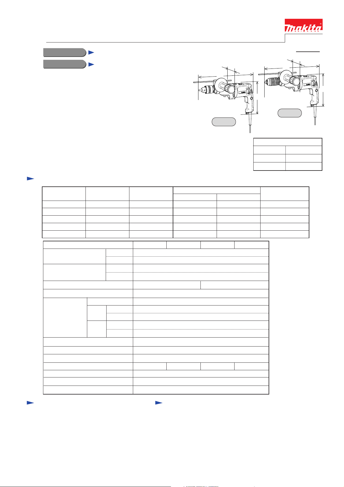
HP2070, HP2070F, HP2071, HP2071F
20mm (3/4") 2-Speed Hammer Drill
CONCEPT AND MAIN APPLICATIONS
NEW TOOL
P 1 /13
W
W
L
L
These hammer drills have been developed as the highest
specification models of Makita hammer drills.
Their features are;
* Powerful 1,010W motor
* New reversing system prevents the speed reduction of
motor in reverse rotation.
* Mechanical 2 speed, and electronic speed adjusting dial
for presetting maximum speed
* LED job light convenient for operations at dimly lit job sites
(HP2070F and HP2071F)
* Keyless drill chuck (HP2071 and HP2071F)
Specification
Voltage (V)
110 1,010 1,100
120
220
230
240
Model No.
No load speed
(min -1= rpm)
Blows per min.
(min -1= bpm)
Drill chuck
Chuck ability (mm [inch])
Drilling capacity
(mm [inch])
Reverse switch
Mechanical speed change
Torque limiter
LED Job light
Protection against electric shock
Cord length (m [ft])
Net weight (kg [lbs])
Current (A)
9.7
8.2
4.8
4.6
4.4
Concrete
Steel
Wood
High
Low
High
Low
High
Low
High
Low
Cycle (Hz)
50 / 60
50 / 60
50 / 60
50 / 60
50 / 60
HP2070 HP2070F
Keyed
No Yes
H
HP2070
Dimensions : mm [inch]
Length ( L )
Height ( H )
Width ( W )
Continuous Rating (W)
Input Output
600
940 1,100
1,010 1,100
1,010 1,100
1,010 1,100
HP2071 HP2071F
0 - 2,900
0 - 1,200
0 - 58,000
0 - 24,000
2.0 - 13 [1/16 - 1/2]
20 [13/16]
8 [5/16]
16 [5/8]
25 [1]
40 [1-9/16]
Yes
2 speed
Yes
No Yes
by double insulation
2.5 [8.2]
2.4 [5.3]
600
600
600
600
Keyless
Max. Output (W)
H
HP2071
362 [14-1/4]
220 [8-5/8]
70 [2-3/4]
Standard equipment
* Depth gauge ................................... 1 pc.
* Side handle set .............................. 1 set
* Plastic carrying case ..................... 1 pc.
* Chuck key S13 (HP2070 and HP2070F) .... 1 pc.
* Key holder (HP2070 and HP2070F) ..... 1 pc.
< Note >
The standard equipment for the tool
may differ from country to country.
Optional accessories
* T.C.T. drill bits Ø 5.0 - Ø 19.0
* Drill bits for steel Ø 5.0 - Ø 13.0
* Drill bits for wood Ø 5.0 - Ø 40.0
* Hole saws Ø 16 - Ø 120
* Metal borer Ø 14 - Ø 35
* Chuck key S13 for HP2070 and HP2070F
* Depth gauge
* Wrench
* Blow out bulb
* Keyless drill chuck set
* Drill chuck set
* Side handle set
* Drill stand type 43
Page 2
Repair
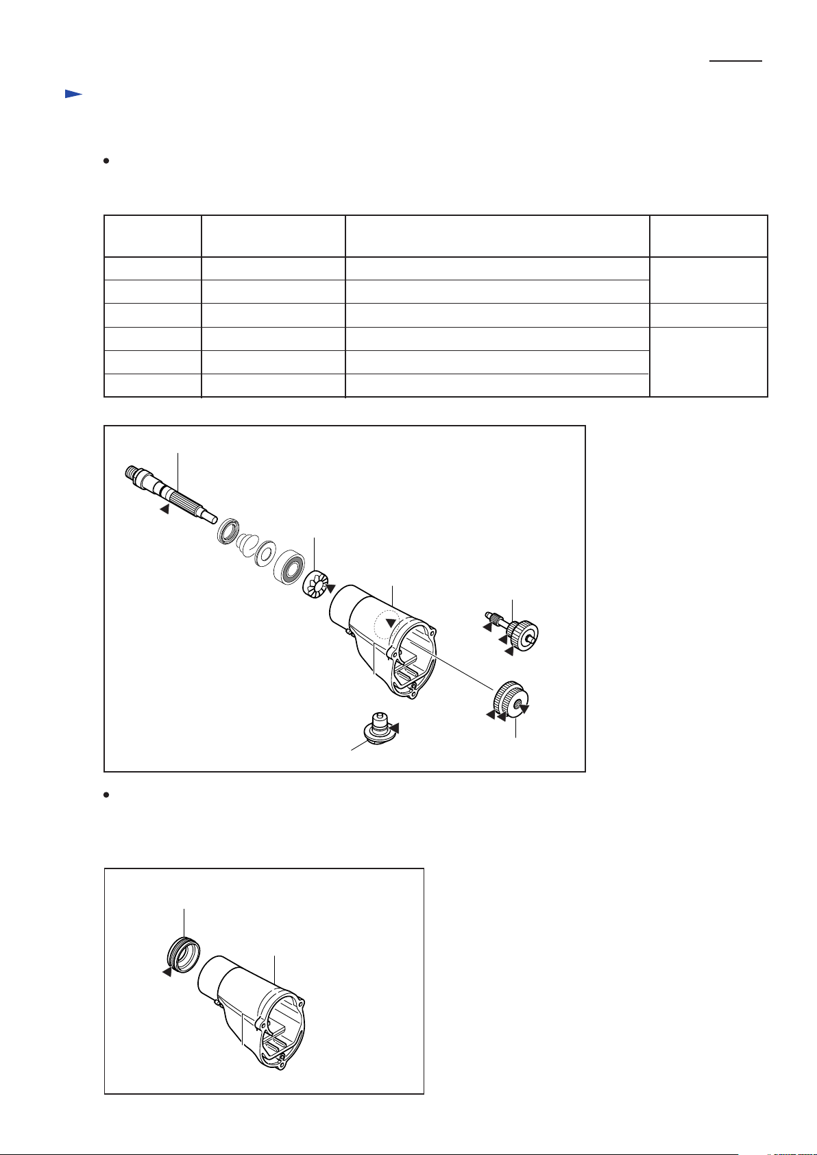
<1> Lubrication and Adhesive Application
Lubrication
Apply Makita grease N No.1 to the following portions designated by the black triangular mark to protect
the parts and the tool from unusual abrasion. (Fig.1)
P 2 /13
Item No. in
parts breakdown
3
8
15
17
19
21
Fig. 1
3
Part name
Spindle Whole surface except threaded portion
Cam A Cam surface
Gear housing complete Gear chamber
Change lever Teethed portion
Gear complete Teeth
Spur gear 29-37 Teeth
8
15
Portion to lubricate
19
Amount
(g [oz])
Proper amount
approx. 25 [7/8]
Proper amount
17
Adhesive Application
Apply TREE BOND 1327 to the threaded portion of Bearing retainer when fastening
Bearing retainer to Gear housing complete. (Fig.2)
Fig. 2
Bearing retainer
Gear housing complete
21
Page 3
P 3 /13
<2> Disassembling and Reassembling Procedures
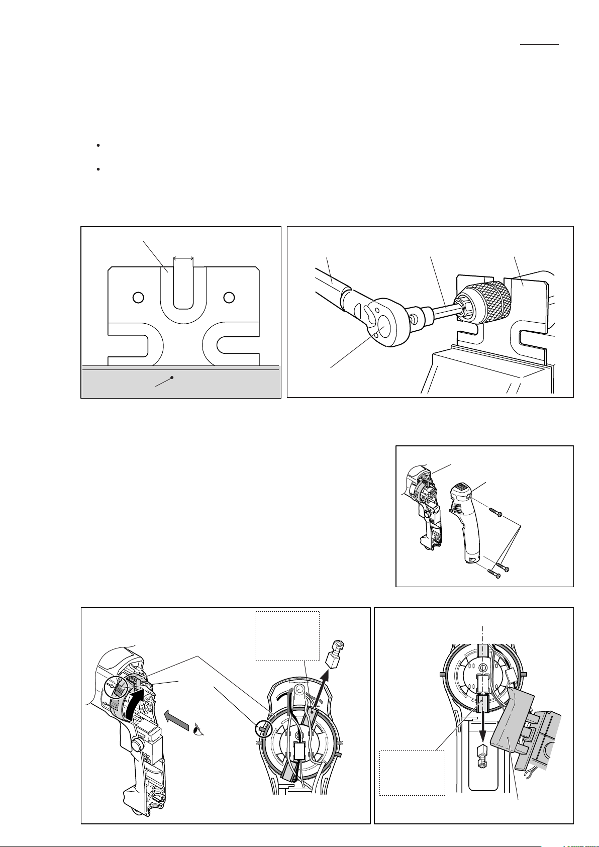
1) Drill Chuck
Disassembly;
1) Secure a Drill chuck extractor (1R139) firmly with a vise as illustrated in Fig. 3.
2) Fix the Spindle on the Drill chuck extractor by inserting the Spindle into the U-shaped notch on the Drill chuck
extractor with the flat sides of the Spindle facing the edges of the notch. And then remove the Drill chuck by
turning it counterclockwise with the repairing tools (1R223, 1R224 and 1R298). (Fig. 4)
Use a pipe wrench to remove the Drill chuck, if the sleeve of the Drill chuck does not turn because of some troubles
with the Drill chuck. Grip the periphery of the sleeve with the wrench, and turn the wrench counterclockwise.
The keyed Drill chuck of HP2070/HP2070F can be removed using a Wrench 43 (781024-2).)
Reassembly;
When fastening the Drill chuck to the Spindle, set the torque of the Torque wrench shaft (1R223) to 35.7 to 45.9 N.m.
Fig. 3
Drill chuck extractor
(1R139)
UT2201
6310
DP4700
8419B
17.0mm (11/16")
HP2031
8420V
8406C
8406
6300L
6300LR
6013BR
6300-4
Fig. 4
Torque wrench shaft
20-90 N.m (1R223)
Ratchet head 12.7
Vise
(1R224)
2) Carbon Brush
Disassembly;
1) Remove the three 4x25 Tapping screws, and separate the Handle cover
from the Motor housing. (Fig. 5)
2) Turn the Brush holder unit (= F/R switch) to reverse position, and then
remove the Carbon brush positioned on the opposite side of the Trigger
switch using a small slotted screwdriver. (Fig. 6)
3) Take the Trigger switch off from the Motor housing, and set the Brush
holder unit in neutral position. And then remove the Carbon brush on
the side of the Trigger switch. (Fig. 7)
Note; The Carbon brush on the side of the Trigger switch cannot be
removed, if you turn the Brush holder unit in neutral position
before separating the Switch trigger from the Motor housing.
Hex. bar 10 with
square socket (1R298)
Fig. 5
Motor housing
Drill chuck extractor
(1R139)
Handle cover
Tapping
screw 4x25
(3pcs)
Fig. 6 Fig. 7
Carbon brush
on the opposite
Brush holder unit
side of Trigger
switch
Reverse
position
(A)
Carbon brush
on the side of
Trigger switch
(view from A)
Trigger switch
Page 4
<2> Disassembling and Reassembling Procedures
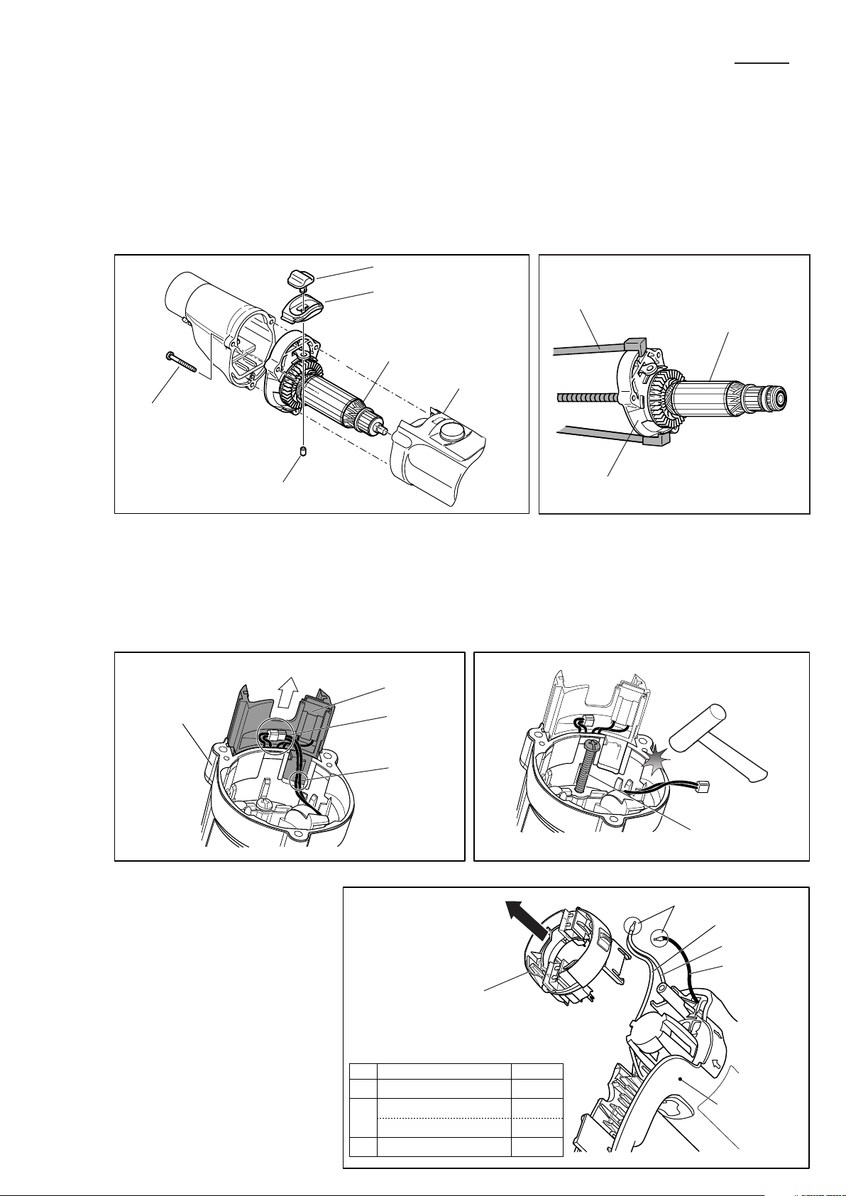
3) Armature assembly
Disassembly;
1) Remove the Carbon brushes as described on page 3. (Fig. 5, 6, 7)
2) Remove the three 4x35 Tapping screws, and then take out of the Motor housing the unit of the Armature assembly
and the Gear housing cover. (Fig. 8)
3) Remove the Rubber Pin 4 to separate the Change lever A and Lever case from the Gear housing cover.
4) And then remove the Gear housing cover from the Armature assembly using a Gear extractor (1R045). (Fig. 9)
5) The Ball bearing 607LLB on the side of commutator can be removed using a Bearing extractor (1R269).)
Fig. 8
Change lever A
Lever case
Fig. 9
Gear extractor (large)
(1R045)
P 4 /13
Armature ass'y with
Gear housing cover
Motor housing
4x35 Tapping
screws (3pcs)
Rubber pin 4
4) Field and Brush holder unit
Disassembly;
1) Shift the Controller till the Connectors appears entirely out of the Motor housing, and disconnect the Connectors that
connect the Controller with the Field. (Fig. 10)
2) In order to remove the Field, remove the two 4x70 Tapping screws, and then gently hit the Motor housing with plastic
or wooden hammer. (Fig. 11)
Fig. 10 Fig. 11
Controller
Motor housing
Connectors
Gear housing cover
Armature ass'y
3) The Brush holder unit can be
removed from the Motor housing
by pulling it in the direction of
the black arrow after disconnecting
the Lead wires which are connected
to the Brush holder unit with the
two Receptacles. (Fig. 12)
Lead wires
from Field
Fig. 12
Brush holder unit
Lead wires
from
ABTrigger switch white
Controller 115V
Controller 220-240V
C Controller black
color
white
blue
Tapping screw
4x70 (2pcs)
Receptacles
Lead wire A
Lead wire B
Lead wire C
Motor housing
Page 5

P 5 /13
Reassembly;
1) When replacing the Field, be sure to remove the Brush holder unit from the Motor housing before installing
a new Field. And install the Brush holder unit after installation of a new Field.
Note: When installing the Brush holder unit on the Motor housing, set the unit so that its two concave portions
face the direction of the Trigger switch. (Fig. 13)
2) When fastening the 4x70 Tapping screws (Field screws), be sure to press the end of the Brush holder unit so that
the unit cannot be pushed out of position. (Fig. 14)
Fig. 13
Fig. 14
Brush
holder unit
Concave portions
5) Gear section
Disassembly;
1) Remove the three 4x35 Tapping screws, and then separate the Gear housing from the Gear housing cover. (Fig. 15)
2) By pulling the Lock plate from the Gear housing, the following parts can be removed from the Gear housing;
Change lever B, Pin 4, Rack 12, Spur gear 29-37 (Fig. 16)
Fig. 15
Gear housing
Gear housing cover
Motor housing
Fig. 16
Gear housing
Push the end of
the Brush holder unit
Spur gear 29-37
Rack 12
Pin 4
Tapping screw
4x35 (3pcs)
Reassembly;
1) Assemble the Spindle section to the Gear housing as illustrated in Fig. 17.
Fig. 17
Bearing retainer with Oil seal 19
Spindle section
(includes Conical compression spring, Ring spring 11
Cup washer 15, Ball bearing 6202LLB and Cam A.)
Note: When assembling the Bearing retainer 20-36 and the Oil seal 19,
refer to " 6) Bearing retainer 20-36 and Oil seal 19" on page 7.
Gear housing
Lock plate
Change lever B
("Reassembly of Gear section" continues to page 6.)
Page 6

P 6 /13
2) Insert the arms of the Change plate B through the slots in the Rack 12, and then put the Spur gear 29-37 between
the arms of the Change plate B. (Fig. 18)
3) Insert the Pin 4 into the Rack 12. Place the Gear housing as illustrated below, and then install the Gear 29-37 on
the Spindle together with the parts you have assembled to the Gear 29-37. (Fig. 19)
At this time, do not fail to set the Leaf spring in place in the Gear housing. (Fig. 19)
Fig. 18
Spur gear 29-37
Rack 12
arm
Change plate B
4) Push the Rack 12 into the Gear housing till
it stops.
And then, install the Change lever B on the
Gear housing with its "I" mark which indicates
low speed aligned with the triangular mark on
the Gear housing. (Fig. 20)
5) Install the Lock plate on the Gear housing with
its tail portion inserted between the ribs on the
Gear housing as illustrated in Fig. 20.
Fig. 19
Gear housing
Spindle
Fig. 20
Spur gear 29-37
Leaf spring
Spur gear 29-37
Pin 4
Rack 12
with change plate B
Spindle
6) Assemble the Gear complete to the Gear housing
as illustrated in Fig. 21.
Note: Do not disassemble the Gear complete,
because it has torque limiter function
and requires very difficult adjustment
when reassembled.
Change lever B
Align with I.
Fig. 21
Rack 12
Ribs
Lock plate
Gear complete
Page 7

P 7 /13
6) Bearing Retainer 20-36 and Oil Seal 19
Disassembly;
1) Using an Adjustable bearing retainer wrench (1R316), remove the Bearing retainer from the Gear housing. (Fig. 22)
As the Bearing retainer has left-hand threads, turn the Bearing retainer 20-36 clockwise for loosening. (Fig. 23)
2) And then remove the Oil seal 19 from the Bearing retainer by deforming the seal with small slotted screwdriver.
Fig. 22
Adjust the distance between the pins on the wrench to the
diagonal distance between two U-shaped depressions on the
Bearing retainer.
Pins
Adjustable bearing
retainer wrench
(1R316)
Reassembly;
1) Press-fit the Oil seal 19 into the Bearing retainer using an arbor press and a Round bar 100 (1R251). (Fig. 24)
Note: When installing a fresh Oil seal 19, apply proper amount of Makita grease N No.1 to its periphery beforehand.
2) Put appropriate amount of Three bond 1327 to the threaded portion of the Bearing retainer.
And then fasten the Bearing retainer securely to the Gear housing by turning it counterclockwise with an Adjustable
bearing retainer wrench (1R316). (Fig. 25)
Fig. 24 Fig. 25
U-shaped depression
Bearing retainer
Fig. 23
Turn clockwise
Arbor press
Round bar 100
(1R251)
Oil seal 19
Bearing retainer
Bearing retainer
Apply Three bond 1327
to the threaded portion
Turn counterclockwise
Page 8

6) Spindle section
Disassembly;
1) Remove the Ring spring 11 from the Spindle section using a Retaining ring S pliers. (Fig. 25)
2) Hold the Ball bearing 6202LLB on the Pipe 30 (1R232), and then, by pressing the Spindle with arbor press,
the following parts can be removed from the Spindle;
Cam A, Ball bearing 6202LLB, Cup washer 15, Conical compression spring (Fig. 26)
P 8 /13
Fig. 25
Spindle section
Slotted screwdriver
Ring spring 11
Retaining ring S pliers
(1R004)
Reassembly;
1) Install the Conical compression spring 15-24 and the Cup washer on the Spindle as illustrated in Fig. 27.
Fig. 27
(armature side)
Spindle
Fig. 26
Cup washer 15
Arbor press
Spindle
Cam A
Ball bearing
6202 LLB
Pipe 30
(1R232)
Cam A
Ball bearing
6202 LLB
Cup washer 15
Conical compression
spring 15-24
Spindle
Conical compression
spring 15-24
[Correct] [Wrong]
(chuck side)
2) Press-fit the Cam A and the Ball bearing 6202LLB onto the Spindle using the following repairing tools;
Arbor press, Bearing setting pipe 15.2-23 (1R029), Bearing setting pipe 17.2-25(1R030),
Bearing setting plate (1R035) (Fig. 28)
Fig. 28
Cam A
Spindle
Cup washer 15
Conical compression
spring 15-24
Ball bearing
6202 LLB
Cam A
Ball bearing
6202 LLB
Bearing setting
plate (1R035)
Arbor press
Bearing setting
pipe (1R029)
Bearing setting
pipe (1R030)
Page 9

Circuit diagram
1) HP2070 & HP2071 (without LED job light)
Color index of lead wires
Black
White
Red
Yellow
P 9 /13
black or brown
white or blue
Power supply cord
Noise
suppressor
1
2
C1
Switch
C2
M1
M2
Color of lead wire;
white (115V)
blue (220-240V)
Brush holder unit
Carbon brush
on the side of Switch
Connectors
Controller
Connectors
Thermistor
Field
Carbon brush
on the opposite side
of Switch
Note: Noise suppressor is not used for some countries.
Page 10

Circuit diagram
2) HP2070F & HP2071F (with LED job light)
Color index of lead wires
Black
White
Red
Yellow
P 10 /13
black or brown
white or blue
Power supply cord
Color of lead wire;
red (115V)
blue (220-240V)
1
2
C1
Switch
C2
M1
M2
Color of lead wire;
white (115V)
blue (220-240V)
Brush holder unit
Carbon brush
on the side of Switch
Connectors
Controller
Connectors
Thermistor
Field
Carbon brush
on the opposite side
of Switch
Noise
suppressor
Case of printed
wiring board
LED
Light circuit
Note: Noise suppressor is not used for some countries.
Page 11

Wiring diagram (1)
1) HP2070 & HP2071 (without LED job light)
Route lead wires as illustrated in Fig. 28.
Fig. 28
A) Fix the two lead wires (a, b) from the Controller at the lead holder.
B) Route the lead wires (a, b, c, d, e, f) from the Controller between the rib and the boss.
C) Fix the white lead wire (c) from the Controller at the lead holders.
D) Fix the red lead wire (b) from the Controller at the lead holders.
E) Route the lead wires (b, g, i, j, k) between the rib and the Switch.
F) Route the lead wires (h) from the Power supply cord between the ribs and the wall of the Motor housing.
P 11 /13
Lead holder
Boss
Rib
D
B
A
a
b
c
d
e
f
C
k
j
Connectors
i
E
Rib
g
Switch
Lead wires
color from
black ControllertoFielda
red Controller Switch
b
white (115V)
c
blue (220-240V)
black Controller Connectord
red Controller Connectore
white Controller Connectorf
white Switch Field
g
black or brown
h
white or blue
black Switch Connectori
red Switch Connectorj
k
yellow Switch Connector
Controller Field
Power supply
cord
Thermistor
via Controller
h
F
Noise suppressor
(not used for some
countries.)
Page 12

Wiring diagram (1)
2) HP2070F & HP2071F (with LED job light)
Route lead wires as illustrated in Fig. 29.
Fig. 29
A) Fix the two lead wires (a, b) from the Controller at the lead holder.
B) Route the lead wires (a, b, c, d, e, f) from the Controller between the rib and the boss.
C) Fix the white lead wire (c) from the Controller at the lead holders.
D) Fix the red lead wire (b) from the Controller at the lead holders.
E) Route the lead wires (b, g, i, j, k) between the rib and the Switch.
F) Route the lead wires (h, l) as illustrated below in "cross section of F".
G) Route the lead wires as illustrated below.
P 12 /13
Lead wires
color from
black Controller
red Controller Switch
b
white (115V)
c
blue (220-240V)
black Controller Connectord
red Controller Connectore
white Controller Connectorf
white Switch Field
g
black or brown
h
white or blue
Controller Field
Power supply
cord
Lead holder
Boss
Rib
to
Fielda
Thermistor
via Controller
D
B
A
a
b
c
d
e
f
C
k
j
Connectors
i
E
Rib
g
Switch
black Switch Connectori
red Switch Connectorj
k
yellow Switch Connector
red (115V)
l
blue (220-240V)
m
white LED
[Cross section of F]
Case of printed
wiring board
Motor housing
Case of printed
wiring board
Switch
Case of printed
wiring board
h (lead wires from
Power supply cord)
l (lead wires from the
Case of printed wiring
board to the Switch)
F
G
m
LED
h
Case of printed
wiring board
Noise suppressor
(Integral part of
Light circuit; not
used for some
countries.)
Page 13

Wiring diagram (2)
For all models
When installing the Brush holder unit on the Motor
housing, set the unit so that its two concave portions
face the direction of the Trigger switch. (Fig. 30)
Place the Connectors as illustrated in Fig. 31.
Do not place it on the side of the U-shaped notch in the
Motor housing.
Note:
Be careful not to pinch the lead wires between the Motor
housing and the Controller.
Fig. 31
Fig. 30
Brush
holder unit
Concave portions
P 13 /13
Motor housing
Controller
Motor housing
Connectors
Do not pinch the lead wires
between the Motor housing
and the Controller.
U-shaped notch
Keyless drill chuck 13
HP2071 & HP2071F
If the Keyless drill chuck 13 cannot be loosened because of a jammed drill bit, take the following procedures to
loosen the chuck;
1) Fix the sleeve section of the chuck securely with an adjustable spanner, etc. (Fig. 31)
Note: Don not fix the retaining section at this time.
2) And then, with a wrench 19, etc, turn the hex. nut on the top of the chuck clockwise to loosen the chuck. (Fig. 31)
Fig. 31
Retaining ring portion
Sleeve portion
Hex nut
Wrench 19
Pipe wrench
 Loading...