

Page 1
G B
2 -S pe e d Ha m m e r Dr il l I ns t ru c tio n Ma nu a l
F
P e r c e u s e à pe rc us s i o n à 2 v it es s e s M a n u e l d’ in s t ru c t io ns
D
2 -G a n g S chl a g b oh rm a s c hi n e B e tr i eb s a n l ei t un g
I
2 ve lo c it à t r a p a n o a pe rc u s s io ne I s tr uz io n i p e r l ’ u s o
N L
2 s ne lh e d e n s l a g bo orm a c hi ne G e b ru ik s a a nw ij z in g
E
2 ve lo c i da d t a l a d ro p e rc u t or M a n u a l d e in s tr uc c i on e s
P
B e r b e q u i m p e rc u t o r c o m 2 v e l o c i d a d e s M a n u a l d e i n s t r u çõe s
DK
2 -ge a r s s la g b ore m a s k i ne B r u gs a nv i s ni ng
G R
H P 20 5 0
H P 20 5 0 F
H P 20 5 1 ( H )
H P 20 5 1 F (H )
2
Page 2
1
4
5
3
2
6
12
8
A
9
B
7
34
10
11
12
13
14
56
16
17
15
78
2
Page 3
18
19
910
20
11
3
Page 4

ENGLISH (Original instructions)
Explanation of general view
1Lock button
2 Speed control screw
3 Switch trigger
4 Higher
5Lower
6Lamp
7 Reversing switch lever
SPECIFICATIONS
Model HP2050/HP2050F HP2051/HP2051F
Speed High Low High Low
Concrete 20 mm ----- 20 mm -----
Capacities
No load speed (min
Blows per minute 0 - 58,000 0 - 24,000 0 - 58,000 0 - 24,000
Overall length 362 mm 360 mm
Net weight 2.5 kg 2.5 kg
Safety class
• Due to our continuing programme of research and
development, the specifications herein are subject to
change without notice.
• Specifications may differ from country to country.
• Weight according to EPTA-Procedure 01/2003
Intended use
The tool is intended for impact drilling in brick, concrete
and stone as well as for drilling without impact in wood,
metal, ceramic and plastic.
Power supply
The tool should be connected only to a power supply of
the same voltage as indicated on the nameplate, and can
only be operated on single-phase AC supply. They are
double-insulated in accordance with European Standard
and can, therefore, also be used from sockets without
earth wire.
General Power Tool Safety Warnings
WARNING Read all safety warnings and all
instructions. Failure to follow the warnings and
instructions may result in electric shock, fire and/or
serious injury.
Save all warnings and instructions for future reference.
Steel 8 mm 13 mm 8 mm 13 mm
Wood 25 mm 40 mm 25 mm 40 mm
–1
) 0 - 2,900 0 - 1,200 0 - 2,900 0 - 1,200
SPECIFIC SAFETY RULES
DO NOT let comfort or familiarity with product
(gained from repeated use) replace strict adherence
to hammer drill safety rules. If you use this power
tool unsafely or incorrectly, you can suffer serious
personal injury.
1. Wear ear protectors with impact drills. Exposure
to noise can cause hearing loss.
2. Use auxiliary handle(s), if supplied with the tool.
Loss of control can cause personal injury.
8 Arrow
9 Speed change knob
10 Action mode changing lever
11 Grip base
12 Side grip (auxiliary handle)
13 Teeth
14 Protrusions
GEA010-1
GEB003-4
15 Chuck key
16 Sleeve
17 Ring
18 Depth gauge
19 Blow-out bulb
20 Vent holes
a/II
3. Hold power tool by insulated gripping surfaces,
when performing an operation where the cutting
accessory may contact hidden wiring or its own
cord. Cutting accessory contacting a “live” wire may
make exposed metal parts of the power tool “live”
and could give the operator an electric shock.
4. Always be sure you have a firm footing.
Be sure no one is below when using the tool in
high locations.
5. Hold the tool firmly with both hands.
6. Keep hands away from rotating parts.
7. Do not leave the tool running. Operate the tool
only when hand-held.
8. Do not touch the bit or the workpiece immediately after operation; they may be extremely hot
and could burn your skin.
9. Some material contains chemicals which may be
toxic. Take caution to prevent dust inhalation
and skin contact. Follow material supplier safety
data.
SAVE THESE INSTRUCTIONS.
WARNING:
MISUSE or failure to follow the safety rules stated in
this instruction manual may cause serious personal
injury.
4
Page 5

FUNCTIONAL DESCRIPTION
CAUTION:
• Always be sure that the tool is switched off and
unplugged before adjusting or checking function on the
tool.
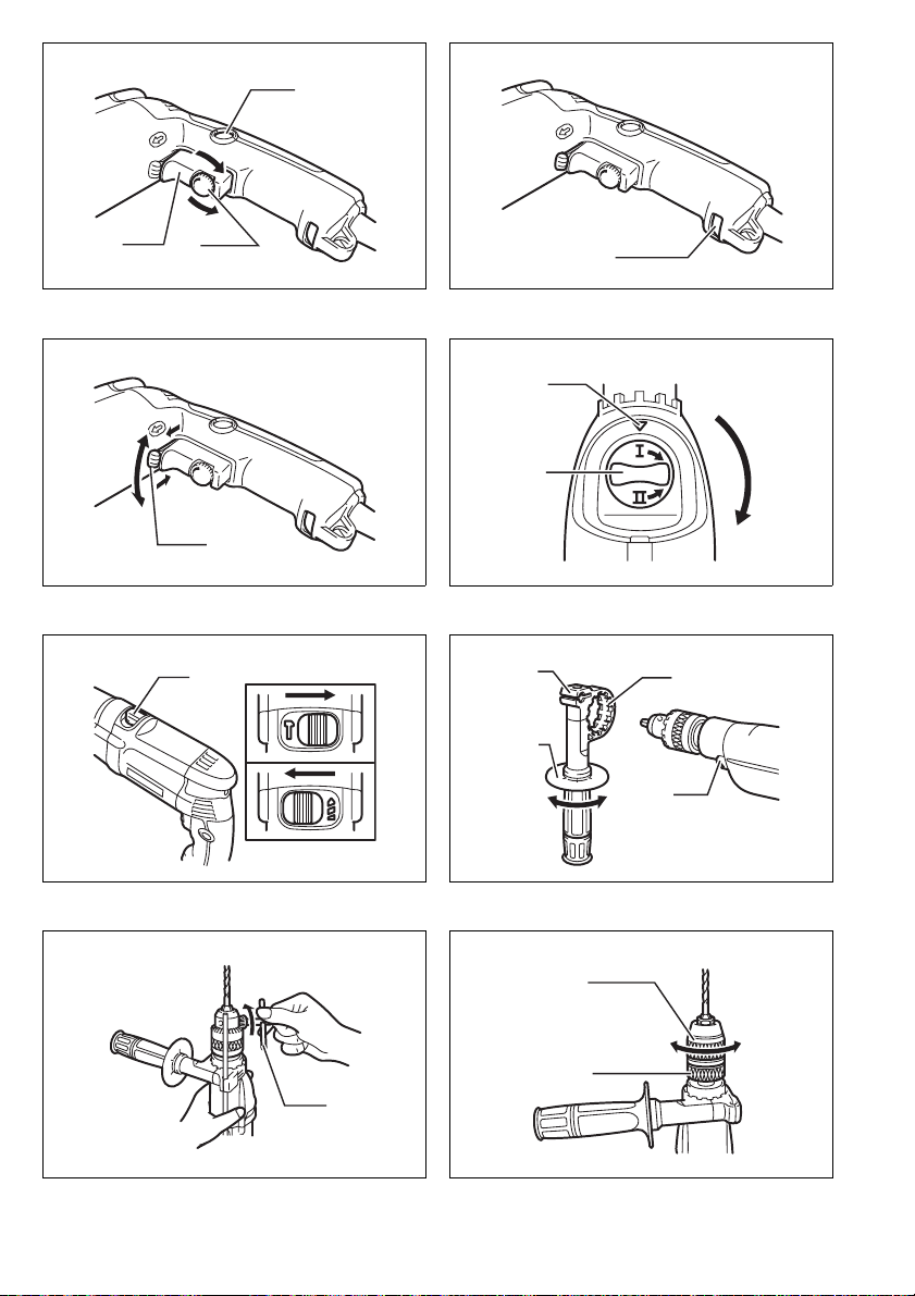
Switch action (Fig. 1)
CAUTION:
• Before plugging in the tool, always check to see that
the switch trigger actuates properly and returns to the
"OFF" position when released.
To start the tool, simply pull the switch trigger. Tool speed
is increased by increasing pressure on the switch trigger.
Release the switch trigger to stop.
For continuous operation, pull the switch trigger and then
push in the lock button.
To stop the tool from the locked position, pull the switch
trigger fully, then release it.
A speed control screw is provided so that maximum tool
speed can be limited (variable). Turn the speed control
screw clockwise for higher speed, and counterclockwise
for lower speed.
Lighting up the lamps
For Model HP2050F, HP2051F (Fig. 2)
CAUTION:
• Do not look in the light or see the source of light
directly.
To turn on the lamp, pull the trigger. Release the trigger
to turn it off.
NOTE:
• Use a dry cloth to wipe the dirt off the lens of lamp. Be
careful not to scratch the lens of lamp, or it may lower
the illumination.
Reversing switch action (Fig. 3)
This tool has a reversing switch to change the direction of
rotation. Move the reversing switch lever to the position (A side) for clockwise rotation or the position
(B side) for counterclockwise rotation.
CAUTION:
• Always check the direction of rotation before operation.
• Use the reversing switch only after the tool comes to a
complete stop. Changing the direction of rotation
before the tool stops may damage the tool.
Speed change (Fig. 4)
Two speed ranges can be preselected with the speed
change knob.
To change the speed, turn the speed change knob so
that the arrow on the tool body points toward the " I "
position on the knob for low speed or " II " position for
high speed.
If it is hard to turn the knob, first turn the chuck slightly in
either direction and then turn the knob again.
CAUTION:
• Use the speed change knob only after the tool comes
to a complete stop. Changing the tool speed before the
tool stops may damage the tool.
• Always set the speed change knob to the correct position. If you operate the tool with the speed change knob
positioned halfway between the " I " and " II " position,
the tool may be damaged.
Selecting the action mode (Fig. 5)
This tool has an action mode change lever. For rotation
with hammering, slide the action mode change lever to
the right (
mode change lever to the left (
CAUTION:
• Always slide the action mode change lever all the way
g symbol). For rotation only, slide the action
m symbol).
to your desired mode position. If you operate the tool
with the lever positioned halfway between the mode
symbols, the tool may be damaged.
ASSEMBLY
CAUTION:
• Always be sure that the tool is switched off and
unplugged before carrying out any work on the tool.
Installing side grip (auxiliary handle) (Fig. 6)
Always use the side grip to ensure operating safety.
Install the side grip so that the teeth on the grip fit in
between the protrusions on the tool barrel.
Then tighten the grip by turning clockwise at the desired
position. It may be swung 360° so as to be secured at
any position.
Installing or removing drill bit
For Model HP2050, HP2050F (Fig. 7)
To install the bit, place it in the chuck as far as it will go.
Tighten the chuck by hand. Place the chuck key in each
of the three holes and tighten clockwise. Be sure to
tighten all three chuck holes evenly.
To remove the bit, turn the chuck key counterclockwise in
just one hole, then loosen the chuck by hand.
After using the chuck key, be sure to return it to the original position.
For Model HP2051, HP2051F (Fig. 8)
Hold the ring and turn the sleeve counterclockwise to
open the chuck jaws. Place the bit in the chuck as far as
it will go. Hold the ring firmly and turn the sleeve clockwise to tighten the chuck.
To remove the bit, hold the ring and turn the sleeve counterclockwise.
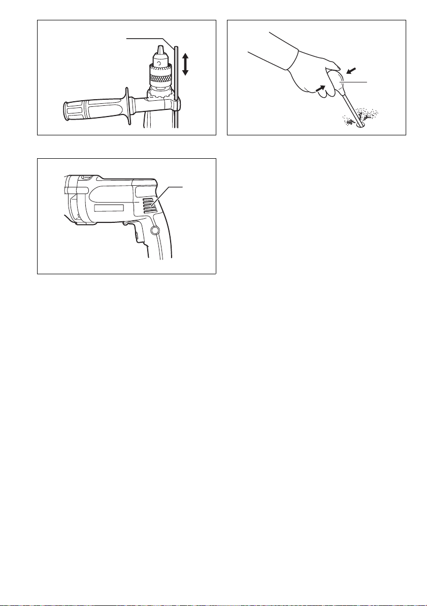
Depth gauge (Fig. 9)
The depth gauge is convenient for drilling holes of uniform depth. Loosen the side grip and insert the depth
gauge into the hole in the grip base. Adjust the depth
gauge to the desired depth and tighten the side grip.
NOTE:
• The depth gauge cannot be used at the position where
the depth gauge strikes against the gear housing.
5
Page 6

OPERATION
Hammer drilling operation
CAUTION:
• There is a tremendous and sudden twisting force
exerted on the tool/bit at the time of hole breakthrough, when the hole becomes clogged with chips
and particles, or when striking reinforcing rods embedded in the concrete. Always use the side grip (auxiliary
handle) and firmly hold the tool by both side grip and
switch handle during operations. Failure to do so may
result in the loss of control of the tool and potentially
severe injury.
When drilling in concrete, granite, tile, etc., move the
action mode change lever to the position of
use "rotation with hammering" action.
Be sure to use a tungsten-carbide tipped bit.
Position the bit at the desired location for the hole, then
pull the switch trigger. Do not force the tool. Light pressure gives best results. Keep the tool in position and prevent it from slipping away from the hole.
Do not apply more pressure when the hole becomes
clogged with chips or particles. Instead, run the tool at an
idle, then remove the bit partially from the hole. By
repeating this several times, the hole will be cleaned out
and normal drilling may be resumed.
Blow-out bulb (optional accessory) (Fig. 10)
After drilling the hole, use the blow-out bulb to clean the
g symbol to
dust out of the hole.
Drilling operation
CAUTION:
• Pressing excessively on the tool will not speed up the
drilling. In fact, this excessive pressure will only serve
to damage the tip of your bit, decrease the tool performance and shorten the service life of the tool.
• There is a tremendous force exerted on the tool/bit at
the time of hole break through. Hold the tool firmly and
exert care when the bit begins to break through the
workpiece.
• A stuck bit can be removed simply by setting the
reversing switch to reverse rotation in order to back out.
However, the tool may back out abruptly if you do not
hold it firmly.
• Always secure small workpieces in a vise or similar
hold-down device.
When drilling in wood, metal or plastic materials, turn the
action mode change lever to the position of
use "rotation only" action.
Drilling in wood
When drilling in wood, the best results are obtained with
wood drills equipped with a guide screw. The guide
screw makes drilling easier by pulling the bit into the
workpiece.
m symbol to
Drilling in metal
To prevent the bit from slipping when starting a hole,
make an indentation with a center-punch and hammer at
the point to be drilled. Place the point of the bit in the
indentation and start drilling.
Use a cutting lubricant when drilling metals. The exceptions are iron and brass which should be drilled dry.
MAINTENANCE
CAUTION:
• Always be sure that the tool is switched off and
unplugged before attempting to perform inspection or
maintenance.
Cleaning vent holes (Fig. 11)
The tool and its air vents have to be kept clean. Regularly
clean the tool’s air vents or whenever the vents start to
become obstructed.
To maintain product SAFETY and RELIABILITY, repairs,
carbon brush inspection and replacement, any other
maintenance or adjustment should be performed by Makita Authorized Service Centers, always using Makita
replacement parts.
ACCESSORIES
CAUTION:
• These accessories or attachments are recommended
for use with your Makita tool specified in this manual.
The use of any other accessories or attachments might
present a risk of injury to persons. Only use accessory
or attachment for its stated purpose.
If you need any assistance for more details regarding
these accessories, ask your local Makita service center.
• Tungsten-carbide tipped hammer bit
• Phillips bits
• Slotted bit
• Hole saws
• Blow-out bulb
• Safety goggles
• Keyless drill chuck 13
• Chuck key
• Grip assembly
• Depth gauge
• Plastic carrying case
For European countries only
Noise
The typical A-weighted noise level determined according
to EN60745:
Sound pressure level (L
Sound power level (L
Uncertainty (K): 3 dB (A)
Wear ear protection
Vai bra tion
The vibration total value (tri-axial vector sum) determined
according to EN60745:
Work mode: impact drilling into concrete
Vibration emission (a
Uncertainty (K): 3 m/s
): 97 dB (A)
pA
): 108 dB (A)
WA
): 13 m/s
h,ID
2
Work mode: driling into metal
Vibration emission (a
Uncertainty (K): 1.5 m/s
• The declared vibration emission value has been measured in accordance with the standard test method and
may be used for comparing one tool with another.
• The declared vibration emission value may also be
used in a preliminary assessment of exposure.
): 2.5 m/s
h,D
2
2
2
or less
ENG102-2
ENG203-2
ENG302-2
ENG901-1
6
Page 7

WARNING:
• The vibration emission during actual use of the power
tool can differ from the declared emission value
depending on the ways in which the tool is used.
• Be sure to identify safety measures to protect the operator that are based on an estimation of exposure in the
actual conditions of use (taking account of all parts of
the operating cycle such as the times when the tool is
switched off and when it is running idle in addition to
the trigger time).
EC Declaration of Conformity
We Makita Corporation as the responsible
manufacturer declare that the following Makita
machine(s):
Designation of Machine: 2-Speed Hammer Drill
Model No./ Type: HP2050, HP2050F, HP2051, HP2051F
are of series production and
Conforms to the following European Directives:
98/37/EC until 28th December 2009 and then with
2006/42/EC from 29th December 2009
And are manufactured in accordance with the following
standards or standardised documents:
EN60745
The technical documentation is kept by our authorized
representative in Europe who is:
Makita International Europe Ltd.
Michigan Drive, Tongwell,
Milton Keynes, MK15 8JD, England
ENH101-12
30th January 2009
Tomoyas u K at o
Director
Makita Corporation
3-11-8, Sumiyoshi-cho,
Anjo, Aichi, JAPAN
7
Page 8

NEDERLANDS (Originele instructies)
Verklaring van algemene gegevens
1 Vastzetknop
2 Snelheidsregelschroef
3 Trekschakelaar
4 Hoger
5 Lager
6Lamp
7 Omkeerschakelaarknop
TECHNISCHE GEGEVENS
Model HP2050/HP2050F HP2051/HP2051F
Snelheid Hoog Laag Hoog Laag
Beton 20 mm ----- 20 mm -----
Capaciteiten
Nullasttoerental (min
Aantal slagen/minuut 0 - 58 000 0 - 24 000 0 - 58 000 0 - 24 000
Totale lengte 362 mm 360 mm
Netto gewicht 2,5 kg 2,5 kg
Veiligheidsklasse
• In verband met ononderbroken research en ontwikkeling behouden wij ons het recht voor bovenstaande
technische gegevens te wijzigen zonder voorafgaande
kennisgeving.
• De technische gegevens kunnen van land tot land verschillen.
• Gewicht volgens de EPTA-procedure 01/2003
Doeleinden van gebruik
Dit gereedschap is bedoeld voor slagboren in baksteen,
beton en steen, en ook voor boren zonder slag in hout,
metaal, keramisch materiaal en kunststof.
Stroomvoorziening
Het gereedschap mag alleen worden aangesloten op
een stroombron van hetzelfde voltage als aangegeven op
de naamplaat, en kan alleen op enkel-fase wisselstroom
worden gebruikt. Het gereedschap is dubbel-geïsoleerd
volgens de Europese standaard en kan derhalve ook op
een niet-geaard stopcontact worden aangesloten.
Algemene veiligheidswaarschuwingen voor
elektrisch gereedschap
WAARSCHUWING! Lees alle veiligheidswaar-
schuwingen en alle instructies. Het niet volgen van de
waarschuwingen en instructies kan leiden tot elektrische
schokken, brand en/of ernstig letsel.
Bewaar alle waarschuwingen en instructies om in de
toekomst te kunnen raadplegen.
Staal 8 mm 13 mm 8 mm 13 mm
Hout 25 mm 40 mm 25 mm 40 mm
–1
) 0 - 2 900 0 - 1 200 0 - 2 900 0 - 1 200
8 Pijltje
9 Snelheidswisselknop
10 Werking-keuzehendel
11 Handgreepvoet
12 Zijhandgreep (hulphandgreep)
13 Tanden
14 Nokken
VEILIGHEIDSVOORSCHRIFTEN
Laat u NIET misleiden door een vals gevoel van comfort en bekendheid met het gereedschap (na veelvuldig gebruik) en neem alle veiligheidsvoorschriften
van de slagschroevendraaier/boorhamer altijd strikt
in acht. Bij onveilig of verkeerd gebruik van het elektrisch gereedschap, bestaat de kans op ernstig persoonlijk letsel.
1. Draag gehoorbescherming tijdens het gebruik
van een boorhamer. Blootstelling aan harde gelui-
den kan leiden tot gehoorbeschadiging.
2. Gebruik de hulphandgreep/hulphandgrepen, als
deze bij het gereedschap werden geleverd.
Verlies van controle over het gereedschap kan persoonlijke verwonding tot gevolg hebben.
GEA010-1
3. Houd elektrisch gereedschap vast aan het geïsoleerde oppervlak van de handgrepen wanneer u
werkt op plaatsen waar het slijpaccessoire met
verborgen bedrading of zijn eigen snoer in aanraking kan komen. Wanneer het booraccessoire in
aanraking komen met onder spanning staande draden, zullen de niet-geïsoleerde metalen delen van
het gereedschap onder spanning komen te staan
zodat de gebruiker een elektrische schok kan krijgen.
4. Zorg ervoor dat u altijd stevige steun voor de
voeten hebt.
Controleer of er zich niemand beneden u bevindt
wanneer u het gereedschap op een hoge plaats
gaat gebruiken.
5. Houd het gereedschap stevig vast met beide
handen.
6. Houd uw handen uit de buurt van draaiende
onderdelen.
15 Boorkopsleutel
16 Bus
17 Ring
18 Dieptemaat
19 Blaasbalgje
20 Ventilatieopeningen
a/II
AANVULLENDE
GEB003-4
20
Page 9

7. Laat het gereedschap niet achter terwijl het nog
in bedrijf is. Bedien het gereedschap alleen wanneer u het met beide handen vasthoudt.
8. Raak de boor of het werkstuk niet aan onmiddellijk na het gebruik. Deze kunnen erg heet zijn en
brandwonden veroorzaken.
9. Sommige materialen bevatten chemische stoffen
die vergiftig kunnen zijn. Vermijd inademing van
stof en contact met de huid. Volg de veiligheidsinstructies van de leverancier van het materiaal.
BEWAAR DEZE VOORSCHRIFTEN.
WAARSCHUWING:
VERKEERD GEBRUIK of het niet naleven van de vei-
ligheidsvoorschriften in deze gebruiksaanwijzing
kan leiden tot ernstige verwondingen.
BESCHRIJVING VAN DE FUNCTIES
LET OP:
• Zorg altijd dat het gereedschap is uitgeschakeld en de
stekker uit het stopcontact is verwijderd alvorens de
functies op het gereedschap af te stellen of te controleren.
Werking van de trekschakelaar (Fig. 1)
LET OP:
• Alvorens de machine op een stopcontact aan te sluiten,
moet u altijd controleren of de trekschakelaar juist
werkt en bij het loslaten naar de “OFF” positie terugkeert.
Om de machine te starten, drukt u gewoon de trekschakelaar in. Hoe dieper de trekschakelaar wordt ingedrukt,
hoe sneller de machine draait. Om de machine uit te
schakelen, de trekschakelaar loslaten.
Voor continuë werking, drukt u de trekschakelaar in en
dan drukt u de vastzetknop in.
Om de machine vanuit deze vergrendelde stand te stoppen, de trekschakelaar volledig indrukken en deze dan
loslaten.
Een snelheidsregelschroef is voorzien zodat de maximale draaisnelheid (variabel) kan worden beperkt. Draai
deze schroef naar rechts voor een hogere snelheid, of
naar links voor een lagere snelheid.
Aanzetten van de lampen
Voor Model HP2050F, HP2051F (Fig. 2)
LET OP:
• Kijk niet direct in het licht of de lichtbron.
Druk de trekker in om de lamp aan te zetten. Laat de
trekker los om de lamp uit te doen.
OPMERKING:
• Gebruik een droge doek om vuil op de lamplens eraf te
vegen. Let op dat u geen krassen maakt op de lamplens, aangezien de verlichtingssterkte daardoor zal verminderen.
Werking van de omkeerschakelaar (Fig. 3)
Dit gereedschap heeft een omkeerschakelaar voor het
veranderen van de draairichting. Schuif de omkeerschakelaar naar de positie (zijde A) voor rechtse draairichting, of naar de positie (zijde B) voor linkse
draairichting.
LET OP:
• Controleer altijd de draairichting alvorens het gereedschap te gebruiken.
• Gebruik de omkeerschakelaar alleen nadat het gereedschap volledig tot stilstand is gekomen. Als u de draairichting verandert voordat het gereedschap is gestopt,
kan het gereedschap beschadigd raken.
Kiezen van het toerental (Fig. 4)
Met de snelheidswisselknop kunt u een van de twee
beschikbare snelheidsbereiken vooraf kiezen.
Draai de instelknop zodanig dat het pijltje op de knop
tegenover “ I ” op het lichaam van het gereedschap komt
te staan voor laag toerental, of tegenover “ II ” voor hoog
toerental.
Als de knop moeilijk te draaien is, moet u de boorkop een
beetje naar links of rechts draaien en daarna de knop
opnieuw draaien.
LET OP:
• Gebruik de snelheidswisselknop alleen nadat het
gereedschap volledig tot stilstand is gekomen. Als u de
draaisnelheid verandert voordat het gereedschap is
gestopt, kan het gereedschap beschadigd raken.
• Zet de snelheidswisselknop altijd juist in een van beide
posities. Als u het gereedschap gebruikt met de knop
halverwege tussen de posities “ I ” en “ II ”, kan het
gereedschap beschadigd raken.
Kiezen van de gewenste werking (Fig. 5)
Dit gereedschap heeft een werking-keuzehendel. Voor
boren plus hameren, schuift u de hendel naar rechts
g symbool). Voor alleen boren, schuift u de hendel naar
(
links (
m symbool).
LET OP:
• Schuif de werking-keuzehendel altijd volledig naar de
gewenste positie. Als u het gereedschap gebruikt met
de hendel halverwege tussen de twee symbolen, kan
het gereedschap beschadigd raken.
INEENZETTEN
LET OP:
• Controleer altijd of het gereedschap is uitgeschakeld
en de stekker uit het stopcontact is verwijderd voordat
u enig werk aan het gereedschap uitvoert.
Installeren van de zijhandgreep (hulphandgreep)
(Fig. 6)
Gebruik altijd de zijhandgreep om een veilige bediening
te verzekeren. Installeer de zijhandgreep zodanig dat de
tanden op de greep tussen de nokken op het huis van de
machine komen te zitten.
Zet dan de handgreep vast door deze in de gewenste
positie naar rechts te draaien. De handgreep kan 360°
worden verdraaid zodat u deze in elke gewenste positie
kunt vastzetten.
21
Page 10

Installeren of verwijderen van de boor
Voor Model HP2050, HP2050F (Fig. 7)
Om de boor te installeren, steekt u deze zo ver mogelijk
in de boorkop. Draai de boorkop met de hand vast. Steek
dan de boorkopsleutel in elk van de drie gaten en draai
naar rechts vast. Zorg ervoor dat u de drie boorkopgaten
gelijkmatig aandraait.
Om de boor te verwijderen, draait u de boorkopsleutel in
één van de gaten naar links en dan draait u de boorkop
verder los met de hand.
Breng de boorkopsleutel na gebruik weer in zijn oorspronkelijke positie aan.
Voor Model HP2051, HP2051F (Fig. 8)
Houd de ring op zijn plaats en draai de bus naar links om
de boorkopklauwen te openen. Steek de boor zo ver
mogelijk in de boorkop. Houd daarna de ring stevig op
zijn plaats en draai de bus naar rechts om de boorkop
vast te zetten.
Om de boor te verwijderen, houdt u de ring op zijn plaats
en draait u de bus naar links.
Diepteaanslag (Fig. 9)
De diepteaanslag is handig voor het boren van gaten van
gelijke diepte. Maak de zijhandgreep los en steek de
diepteaanslag in het gat in de handgreepvoet. Stel de
diepteaanslag af op de gewenste diepte en zet de zijhandgreep vast.
OPMERKING:
• De diepteaanslag kan niet worden gebruikt in de positie waarbij deze tegen het tandwielhuis aanstoot.
BEDIENING
Hameren plus boren
LET OP:
• Op het moment dat de boor door het gat heen dringt, of
wanneer het boorgat verstopt raakt met spanen en
metaaldeeltjes, of wanneer het gereedschap op versterkingsstaven in gewapend beton stoot, wordt er plotseling een enorme wringingskracht op het
gereedschap/boor uitgeoefend. Gebruik daarom altijd
de zijhandgreep (hulphandgreep) en houd het gereedschap tijdens het gebruik stevig vast bij zowel de zijhandgreep als de hoofdhandgreep. Als u dit niet doet,
kunt u de controle over het gereedschap verliezen en
mogelijk zware verwondingen oplopen.
Voor het boren in beton, graniet, tegels e.d., moet u de
werking-keuzehendel naar de positie van het
schuiven voor “hameren plus boren”.
Gebruik een boor met wolfraamcarbidepunt.
Plaats de boorpunt op de plaats waar u wilt boren en
druk de trekschakelaar in. Forceer het gereedschap niet.
Een lichte druk geeft de beste resultaten. Houd het
gereedschap stevig vast en zorg dat de boor niet uit het
gat wegslipt.
Oefen geen grotere druk uit wanneer het boorgat verstopt raakt met spanen of schilfertjes. Laat in plaats daarvan het gereedschap onbelast draaien en verwijder de
boor gedeeltelijk uit het boorgat. Wanneer u dit een paar
keer herhaalt, zal het boorgat schoon worden en kunt u
normaal verder boren.
gsymbool
Blaasbalgje (los verkrijgbaar accessoire) (Fig. 10)
Gebruik het blaasbalgje nadat het gat is geboord, om stof
uit het gat weg te blazen.
Boren
LET OP:
• Door teveel druk op het gereedschap uit te oefenen
verloopt het boren niet sneller. Integendeel, teveel druk
op het gereedschap zal alleen maar de boor beschadigen, de prestatie van het gereedschap verminderen en
de gebruiksduur verkorten.
• Op het ogenblik dat de boor uit het gat tevoorschijn
komt, wordt een enorme kracht uitgeoefend op het
gereedschap en de boor. Houd daarom het gereedschap stevig vast en wees op uw hoede wanneer de
boor doorheen het werkstuk begint te komen.
• Wanneer de boor klemraakt, keert u met de omkeerschakelaar de draairichting om, om de boor uit het gat
te krijgen. Pas echter op en houd het gereedschap stevig vast, aangezien het anders uit het gat weg kan
schieten.
• Kleine werstukken dient u altijd eerst vast te zetten met
een klemschroef of iets dergelijks.
Voor het boren in hout, metaal of kunststof, moet u de
werking-keuzehendel naar de positie van het
schuiven voor “alleen boren”.
Boren in hout
Voor boren in hout worden de beste resultaten verkregen
met houtboren die voorzien zijn van een geleideschroef.
Het boren wordt dan vergemakkelijkt aangezien de geleideschroef de boor in het hout trekt.
Boren in metaal
Wanneer u begint te boren, gebeurt het dikwijls dat de
boor slipt. Om dit te voorkomen slaat u tevoren met een
drevel een deukje in het metaal op de plaats waar u wilt
boren. Plaats vervolgens de boor in het deukje en start
het boren.
Gebruik altijd boorolie wanneer u in metaal boort. De
einige uitzonderingen zijn ijzer en koper die “droog”
geboord dienen te worden.
ONDERHOUD
LET OP:
• Zorg altijd dat het gereedschap is uitgeschakeld en de
stekker uit het stopcontact is verwijderd alvorens inspectie of onderhoud aan het gereedschap uit te voeren.
m symbool
Reinigen van de ventilatieopeningen (Fig. 11)
Houd het gereedschap en zijn ventilatiegaten altijd
schoon. Reinig regelmatig de ventilatiegaten om te voorkomen dat deze verstopt raken.
Om de VEILIGHEID en BETROUWBAARHEID van het
gereedschap te handhaven, dienen alle reparaties,
inspectie en vervanging van de koolborstels, en alle
andere onderhoudswerkzaamheden of afstellingen te
worden uitgevoerd bij een erkend Makita servicecentrum
of fabriekscentrum, en altijd met gebruik van originele
Makita vervangingsonderdelen.
22
Page 11

ACCESSOIRES
LET OP:
• Deze accessoires of hulpstukken worden aanbevolen
voor gebruik met het Makita gereedschap dat in deze
gebruiksaanwijzing wordt beschreven. Het gebruik van
andere accessoires of hulpstukken kan gevaar voor
persoonlijke verwonding opleveren. Gebruik de accessoires of hulpstukken uitsluitend voor het gespecificeerde doel.
Wenst u meer informatie over deze accessoires, neem
dan contact op met het dichtstbijzijnde Makita servicecentrum.
• Boor met wolfraamcarbide boorpunt
• Phillips schroefbit
• Gesleufde bit
• Gatzagen
• Blaasbalgje
• Veiligheidsbril
• Sleutelloze boorkop 13
• Boorkop
• Handgreepmontage
• Dieptemaat
• Plastic draagkoffer
Alleen voor Europese landen
Geluidsniveau
De typisch, A-gewogen geluidsniveaus vastgesteld volgens EN60745:
Geluidsdrukniveau (L
Geluidsenergie-niveau (L
Onnauwkeurigheid (K): 3 dB (A)
Draag oorbeschermers
Trilling
De totaalwaarde van de trillingen (triaxiale vectorsom)
vastgesteld volgens EN60745:
Toepassing: hamerboren in beton
Trillingsemissie (a
Onnauwkeurigheid (K): 3 m/s
Toepassing: boren in metaal
Trillingsemissie (a
Onnauwkeurigheid (K): 1,5 m/s
): 97 dB (A)
pA
): 108 dB (A)
WA
2
): 13 m/s
h,ID
h,D
2
): 2,5 m/s2 of lager
• De opgegeven trillingsemissiewaarde is gemeten volgens de standaardtestmethode en kan worden gebruikt
om dit gereedschap te vergelijken met andere gereedschappen.
• De opgegeven trillingsemissiewaarde kan ook worden
gebruikt voor een beoordeling vooraf van de blootstelling.
WAARSCHUWING:
• De trillingsemissie tijdens het gebruik van het elektrisch
gereedschap in de praktijk kan verschillen van de
opgegeven trillingsemissiewaarde afhankelijk van de
manier waarop het gereedschap wordt gebruikt.
• Zorg ervoor dat veiligheidsmaatregelen worden getroffen ter bescherming van de operator die zijn gebaseerd
op een schatting van de blootstelling onder praktijkomstandigheden (rekening houdend met alle fasen van de
bedrijfscyclus, zoals de tijdsduur gedurende welke het
gereedschap is uitgeschakeld en stationair draait,
naast de ingeschakelde tijdsduur).
ENG102-2
ENG203-2
ENG302-2
2
ENG901-1
EU-Verklaring van Conformiteit
Wij, Makita Corporation, als de verantwoordelijke
fabrikant, verklaren dat de volgende Makitamachine(s):
Aanduiding van de machine: 2 snelheden
Modelnr./Type: HP2050, HP2050F, HP2051, HP2051F
in serie zijn geproduceerd en
Voldoen aan de volgende Europese richtlijnen:
98/37/EC tot en met 28 december 2009 en daarna
aan 2006/42/EC vanaf 29 december 2009
En zijn gefabriceerd in overeenstemming met de volgende normen of genormaliseerde documenten:
EN60745
De technische documentatie wordt bewaard door onze
erkende vertegenwoordiger in Europa, te weten:
Makita International Europe Ltd.
Michigan Drive, Tongwell,
Milton Keynes, MK15 8JD, Engeland
slagboormachine
ENH101-12
30 januari 2009
Tomoyasu Kato
Directeur
Makita Corporation
3-11-8, Sumiyoshi-cho,
Anjo, Aichi, JAPAN
23
Page 12

Makita Corporation
Anjo, Aichi Japan
884428E995
 Loading...