

Makita HP2051F, HP2050, HP2050F User Manual
INSTRUCTION MANUAL
MANUEL D'INSTRUCTION
MANUAL DE INSTRUCCIONES
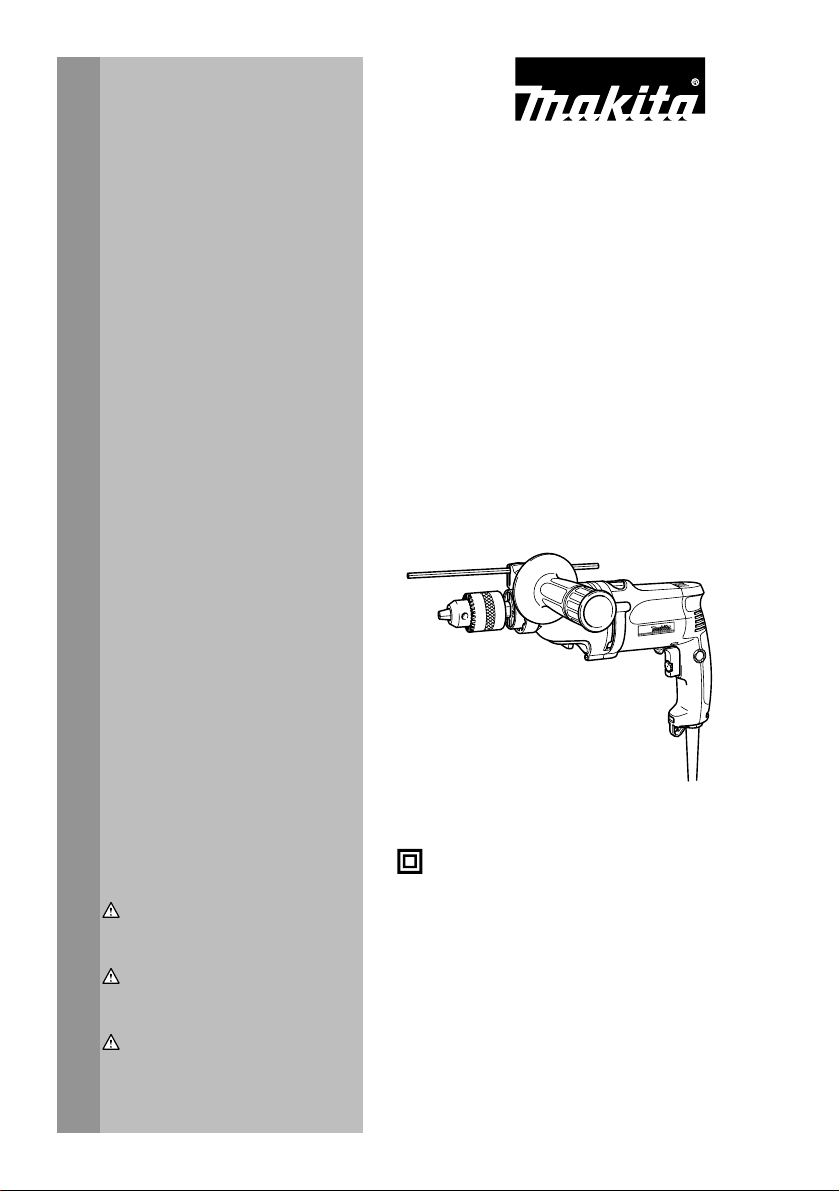
2-Speed Hammer Drill
Perceuse à Percussion 2-Vitesses
2 Velocidad Taladro de percusión
HP2050
HP2050F
HP2051F
002989
DOUBLE INSULATION
DOUBLE ISOLATION
WARNING:
For your personal safety, READ and UNDERSTAND before using.
SAVE THESE INSTRUCTIONS FOR FUTURE REFERENCE.
AVERTISSEMENT:
Pour votre propre sécurité, prière de lire attentivement avant l'utilisation.
GARDER CES INSTRUCTIONS POUR RÉFÉRENCE ULTÉRIEURE.
ADVERTENCIA:
Para su seguridad personal, LEA DETENIDAMENTE este manual antes de usar la
herramienta.
GUARDE ESTAS INSTRUCCIONES PARA FUTURA REFERENCIA.
DOBLE AISLAMIENTO
1

ENGLISH
SPECIFICATIONS
Model HP2050/2050F HP2051F
Speed High Low High Low
Capacities
No load speed (RPM)
Blows per minute 0 - 58,000 0 - 24,000 0 - 58,000 0 - 24,000
Overall length 362 mm (14-1/4") 360 mm (14-1/8")
• Due to our continuing programme of research and development, the specifications herein are subject to change without notice.
• Specifications may differ from country to country.
• Weight according to EPTA-Procedure 01/2003
Net weight 2.5 kg (5.6 lbs) 2.5 kg (5.6 lbs)
GENERAL SAFETY RULES
(For All Tools)
WARNING! Read and understand all instructions.
Failure to follow all instructions listed below, may result
in electric shock, fire and/or serious personal injury.
SAVE THESE INSTRUCTIONS.
Work Area
1. Keep your work area clean and well lit.
Cluttered benches and dark areas invite
accidents.
2. Do not operate power tools in explosive
atmospheres, such as in the presence of
flammable liquids, gases or dust. Power tools
create sparks which may ignite the dust or fumes.
3. Keep bystanders, children, and visitors away
while operating a power tool. Distractions can
cause you to lose control.
Electrical Safety
4. Double insulated tools are equipped with a
polarized plug ( one blade is wider than the
other.) This plug will fit in a polarized outlet
only one way. If the plug does not fit fully in the
outlet, reverse the plug. If it still does not fit,
contact a qualified electrician to install a
polarized outlet. Do not change the plug in any
way. Double insulation
the three wire grounded power cord and grounded
power supply system.
5. Avoid body contact with grounded surfaces
such as pipes, radiators, ranges and
refrigerators. There is an increased risk of
electric shock if your body is grounded.
Concrete 20 mm (3/4") ----- 20 mm (3/4") -----
Steel 8 mm (5/16") 13 mm (1/2") 8 mm (5/16") 13 mm (1/2")
Wood
USA002-2
25 mm (1") 40 mm (1-9/16") 25 mm (1") 40 mm (1-9/16")
0 - 2,900/min. 0 - 1,200/min. 0 - 2,900/min. 0 - 1,200/min.
6. Do not expose power tools to rain or wet
conditions. Water entering a power tool will
increase the risk of electric shock.
7. Do not abuse the cord. Never use the cord to
carry the tools or pull the plug from an outlet.
Keep cord away from heat, oil, sharp edges or
moving parts. Replace damaged cords
immediately. Damaged cords increase the risk of
electric shock.
8. When operating a power tool outside, use an
outdoor extension cord marked "W-A" or "W".
These cords are rated for outdoor use and reduce
the risk of electric shock.
Personal Safety
9. Stay alert, watch what you are doing and use
common sense when operating a power tool.
Do not use tool while tired or under the
influence of drugs, alcohol, or medication. A
moment of inattention while operating power tools
may result in serious personal injury.
10. Dress properly. Do not wear loose clothing or
jewelry. Contain long hair. Keep your hair,
clothing, and gloves away from moving parts.
Loose clothes, jewelry, or long hair can be caught
in moving parts.
11. Avoid accidental starting. Be sure switch is off
before plugging in. Carrying tools with your
finger on the switch or plugging in tools that have
the switch on invites accidents.
12. Remove adjusting keys or wrenches before
eliminates the need for
turning the tool on. A wrench or a key that is left
attached to a rotating part of the tool may result in
personal injury.
13. Do not overreach. Keep proper footing and
balance at all times. Proper footing and balance
enables better control of the tool in unexpected
situations.
2

14. Use safety equipment. Always wear eye
protection. Dust mask, non-skid safety shoes,
hard hat, or hearing protection must be used for
appropriate conditions. Ordinary eye or sun
glasses are NOT eye protection.
Tool Use and Care
15. Use clamps or other practical way to secure
and support the workpiece to a stable platform.
Holding the work by hand or against your body is
unstable and may lead to loss of control.
16. Do not force tool. Use the correct tool for your
application. The correct tool will do the job better
and safer at the rate for which it is designed.
17. Do not use tool if switch does not turn it on or
off. Any tool that cannot be controlled with the
switch is dangerous and must be repaired.
18. Disconnect the plug from the power source
before making any adjustments, changing
accessories, or storing the tool. Such
preventive safety measures reduce the risk of
starting the tool accidentally.
19. Store idle tools out of reach of children and
other untrained persons. Tools are dangerous in
the hands of untrained users.
20. Maintain tools with care. Keep cutting tools
sharp and clean. Properly maintained tools with
sharp cutting edges are less likely to bind and are
easier to control.
21. Check for misalignment or binding of moving
parts, breakage of parts, and any other
condition that may affect the tool’s operation.
If damaged, have the tool serviced before
using. Many accidents are caused by poorly
maintained tools.
22. Use only accessories that are recommended
by the manufacturer for your model.
Accessories that may be suitable for one tool,
may become hazardous when used on another
tool.
SERVICE
23. Tool service must be performed only by
qualified repair personnel. Service or
maintenance performed by unqualified personnel
could result in a risk of injury.
24. When servicing a tool, use only identical
replacement parts. Follow instructions in the
Maintenance section of this manual. Use of
unauthorized parts or failure to follow
Maintenance instructions may create a risk of
electric shock or injury.
USE PROPER EXTENSION CORD. Make sure your
extension cord is in good condition. When using an
extension cord, be sure to use one heavy enough to
carry the current your product will draw. An
undersized cord will cause a drop in line voltage
resulting in loss of power and overheating. Table 1
shows the correct size to use depending on cord
length and nameplate ampere rating. If in doubt, use
the next heavier gage. The smaller the gage number,
the heavier the cord.
Table 1: Minimum gage for cord
Ampere Rating
Volts Total length of cord in feet
120 V 25 ft. 50 ft. 100 ft. 150 ft.
More Than Not More Than AWG
0 6 18 16 16 14
18 16 14 12610
10 12 16 16 14 12
000173
SPECIFIC SAFETY RULES
DO NOT let comfort or familiarity with product
(gained from repeated use) replace strict adherence
to hammer drill safety rules. If you use this tool
unsafely or incorrectly, you can suffer serious
personal injury.
12 16 14 12
USB002-2
1. Hold tool by insulated gripping surfaces when
performing an operation where the cutting tool
may contact hidden wiring or its own cord.
Contact with a "live" wire will make exposed metal
parts of the tool "live" and shock the operator.
2. Always be sure you have a firm footing.
Be sure no one is below when using the tool in
high locations.
3
Not Recommended
3. Hold the tool firmly with both hands. Always
use the side grip.
4. Keep hands away from rotating parts.
5. Do not leave the tool running. Operate the tool
only when hand-held.
6. Do not touch the bit or the workpiece
immediately after operation; they may be
extremely hot and could burn your skin.
7. Some material contains chemicals which may
be toxic. Take caution to prevent dust
inhalation and skin contact. Follow material
supplier safety data.
SAVE THESE INSTRUCTIONS.
WARNING:
MISUSE or failure to follow the safety rules stated in
this instruction manual may cause serious personal
injury.
USD202-2
Symbols
The followings show the symbols used for tool.
・ volts
・ amperes
・ hertz
・ alternating current
・ no load speed
・ Class II Construction
・ revolutions or reciprocation per minute
・ number of blow
FUNCTIONAL DESCRIPTION
CAUTION:
• Always be sure that the tool is switched off and
unplugged before adjusting or checking function on
the tool.
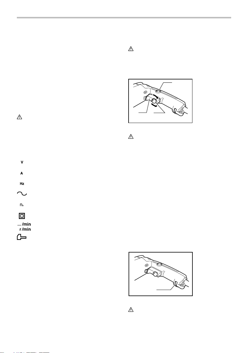
Switch action
1
4
5
3
2
002990
CAUTION:
• Before plugging in the tool, always check to see
that the switch trigger actuates properly and
returns to the "OFF" position when released.
• Switch can be locked in "ON" position for ease of
operator comfort during extended use. Apply
caution when locking tool in "ON" position and
maintain firm grasp on tool.
To start the tool, simply pull the switch trigger. Tool
speed is increased by increasing pressure on the switch
trigger. Release the switch trigger to stop.
For continuous operation, pull the switch trigger and
then push in the lock button.
To stop the tool from the locked position, pull the switch
trigger fully, then release it.
A speed control screw is provided so that maximum tool
speed can be limited (variable). Turn the speed control
screw clockwise for higher speed, and counterclockwise
for lower speed.
Lighting up the lamps
For Model HP2050F, HP2051F
1
002689
CAUTION:
• Do not look in the light or see the source of light
directly.
1. Lock button
2. Speed control
screw
3. Switch trigger
4. Higher
5. Lower
1. Lamp
4
To turn on the lamp, pull the trigger. Release the trigger
to turn it off.
NOTE:
• Use a dry cloth to wipe the dirt off the lens of lamp.
Be careful not to scratch the lens of lamp, or it may
lower the illumination.
Reversing switch action
1. Reversing
switch lever
A
B
1
002991
This tool has a reversing switch to change the direction
of rotation. Move the reversing switch lever to
the
position (A side) for clockwise rotation or
the
position (B side) for counterclockwise rotation.
CAUTION:
• Always check the direction of rotation before
operation.
• Use the reversing switch only after the tool comes
to a complete stop. Changing the direction of
rotation before the tool stops may damage the tool.
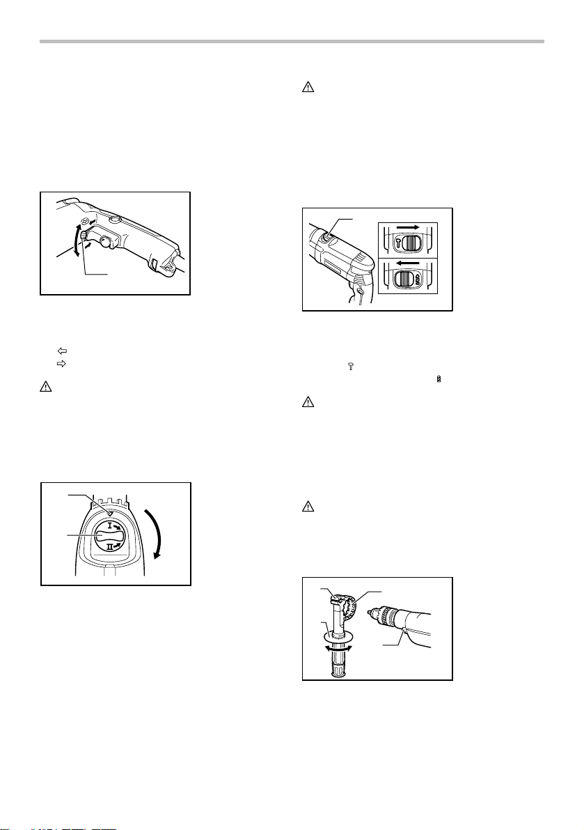
Speed change
1
2
002691
Two speed ranges can be preselected with the speed
change knob.
To change the speed, turn the speed change knob so
that the arrow on the tool body points toward the "I"
position on the knob for low speed or "II" position for
high speed.
If it is hard to turn the knob, first turn the chuck slightly in
either direction and then turn the knob again.
1. Arrow
2. Speed change
knob
CAUTION:
• Use the speed change knob only after the tool
comes to a complete stop. Changing the tool
speed before the tool stops may damage the tool.
• Always set the speed change knob to the correct
position. If you operate the tool with the speed
change knob positioned halfway between the "I"
and "II" position, the tool may be damaged.
Selecting the action mode
1
002692
This tool has an action mode change lever. For rotation
with hammering, slide the action mode change lever to
the right (
mode change lever to the left (
symbol). For rotation only, slide the action
CAUTION:
• Always slide the action mode change lever all the
way to your desired mode position. If you operate
the tool with the lever positioned halfway between
the mode symbols, the tool may be damaged.
1. Action mode
changing lever
symbol).
ASSEMBLY
CAUTION:
• Always be sure that the tool is switched off and
unplugged before carrying out any work on the
tool.
Installing side grip (auxiliary handle)
1. Grip base
2. Side grip
(auxiliary
handle)
3. Teeth
4. Protrusions
5
1
2
002693
3
4
Always use the side grip to ensure operating safety.
Install the side grip so that the teeth on the grip fit in
between the protrusions on the tool barrel.
Then tighten the grip by turning clockwise at the desired
position. It may be swung 360° so as to be secured at
any position.
Installing or removing drill bit
For Model HP2050, HP2050F
1. Chuck key
1
002694
To install the bit, place it in the chuck as far as it will go.
Tighten the chuck by hand. Place the chuck key in each
of the three holes and tighten clockwise. Be sure to
tighten all three chuck holes evenly.
To remove the bit, turn the chuck key counterclockwise
in just one hole, then loosen the chuck by hand.
After using the chuck key, be sure to return to the
original position.
For Model HP2051F
1
2
002695
Hold the ring and turn the sleeve counterclockwise to
open the chuck jaws. Place the bit in the chuck as far as
it will go. Hold the ring firmly and turn the sleeve
clockwise to tighten the chuck.
To remove the bit, hold the ring and turn the sleeve
counterclockwise.
1. Sleeve
2. Ring
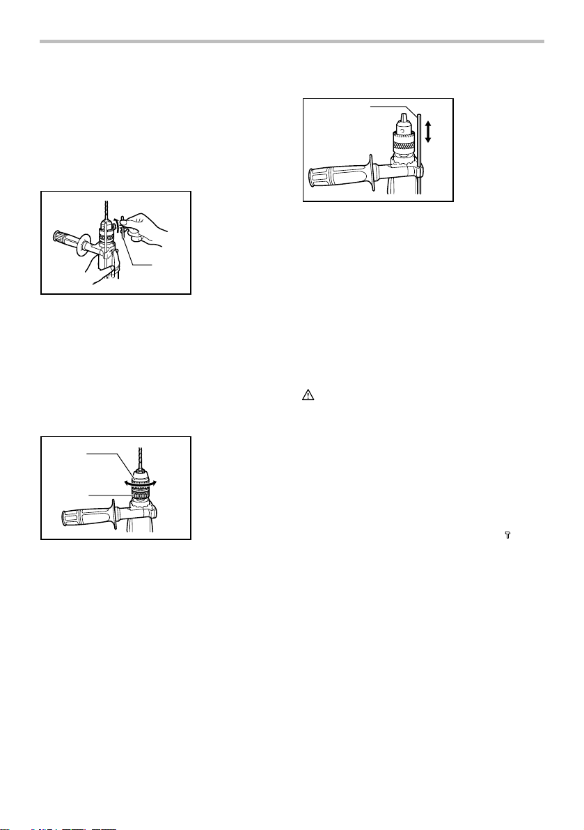
Depth gauge
1
002696
The depth gauge is convenient for drilling holes of
uniform depth. Loosen the side grip and insert the depth
gauge into the hole in the side grip. Adjust the depth
gauge to the desired depth and tighten the side grip.
NOTE:
• The depth gauge cannot be used at the position
where the depth gauge strikes against the tool
body.
1. Depth gauge
OPERATION
Hammer drilling operation
CAUTION:
• There is a tremendous and sudden twisting force
exerted on the tool/bit at the time of hole
break-through, when the hole becomes clogged
with chips and particles, or when striking
reinforcing rods embedded in the concrete. Always
use the side grip (auxiliary handle) and firmly hold
the tool by both side grip and switch handle during
operations. Failure to do so may result in the loss
of control of the tool and potentially severe injury.
When drilling in concrete, granite, tile, etc., move the
action mode changing lever to the position of
to use "rotation with hammering" action.
Be sure to use a tungsten-carbide tipped bit.
Position the bit at the desired location for the hole, then
pull the switch trigger. Do not force the tool. Light
pressure gives best results. Keep the tool in position and
prevent it from slipping away from the hole.
Do not apply more pressure when the hole becomes
clogged with chips or particles. Instead, run the tool at
an idle, then remove the bit partially from the hole. By
repeating this several times, the hole will be cleaned out
and normal drilling may be resumed.
6
symbol
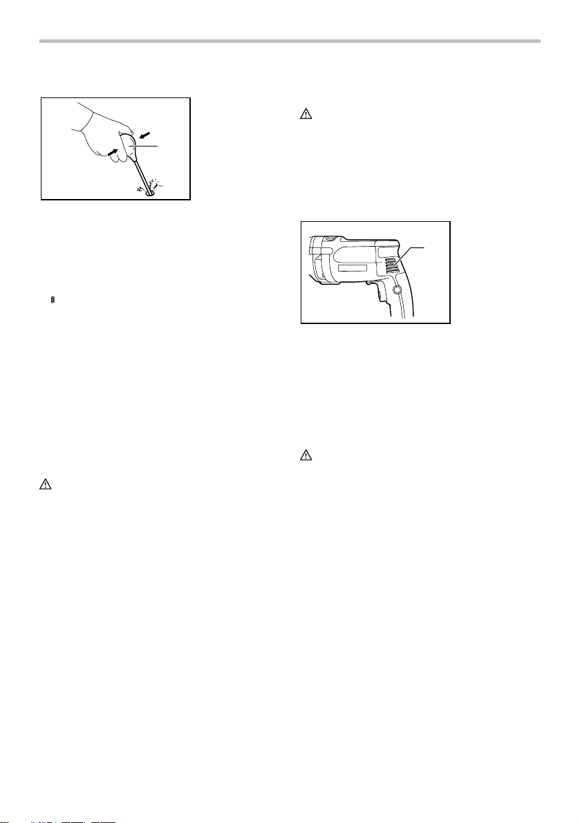
Blow-out bulb (optional accessory)
1. Blow-out bulb
1
002449
After drilling the hole, use the blow-out bulb to clean the
dust out of the hole.
Drilling operation
When drilling in wood, metal or plastic materials, move
the action mode changing lever to the position
of
symbol to use "rotation only" action.
Drilling in wood
When drilling in wood, the best results are obtained with
wood drills equipped with a guide screw. The guide
screw makes drilling easier by pulling the bit into the
workpiece.
Drilling in metal
To prevent the bit from slipping when starting a hole,
make an indentation with a center-punch and hammer at
the point to be drilled. Place the point of the bit in the
indentation and start drilling.
Use a cutting lubricant when drilling metals. The
exceptions are iron and brass which should be drilled
dry.
CAUTION:
• Pressing excessively on the tool will not speed up
the drilling. In fact, this excessive pressure will only
serve to damage the tip of your bit, decrease the
tool performance and shorten the service life of the
tool.
• There is a tremendous force exerted on the tool/bit
at the time of hole break through. Hold the tool
firmly and exert care when the bit begins to break
through the workpiece.
• A stuck bit can be removed simply by setting the
reversing switch to reverse rotation in order to back
out. However, the tool may back out abruptly if you
do not hold it firmly.
• Always secure small workpieces in a vise or similar
hold-down device.
MAINTENANCE
CAUTION:
• Always be sure that the tool is switched off and
unplugged before attempting to perform inspection
or maintenance.
Cleaning vent holes
The tool and its air vents have to be kept clean.
Regularly clean the tool's air vents or whenever the
vents start to become obstructed.
1. Vent holes
1
002697
To maintain product SAFETY and RELIABILITY, repairs,
carbon brush inspection and replacement, any other
maintenance or adjustment should be performed by
Makita Authorized or Factory Service Centers, always
using Makita replacement parts.
ACCESSORIES
CAUTION:
• These accessories or attachments are
recommended for use with your Makita tool
specified in this manual. The use of any other
accessories or attachments might present a risk of
injury to persons. Only use accessory or
attachment for its stated purpose.
If you need any assistance for more details regarding
these accessories, ask your local Makita Service Center.
• Drill bits
• Hammer drill bits
• Hole saws
• Blow-out bulb
• Safety goggles
• Chuck key
• Grip assembly
• Depth gauge
• Plastic carrying case
7

MAKITA LIMITED ONE YEAR WARRANTY
Warranty Policy
Every Makita tool is thoroughly inspected and tested
before leaving the factory. It is warranted to be free of
defects from workmanship and materials for the period
of ONE YEAR from the date of original purchase.
Should any trouble develop during this one year period,
return the COMPLETE tool, freight prepaid, to one of
Makita’s Factory or Authorized Service Centers. If
inspection shows the trouble is caused by defective
workmanship or material, Makita will repair (or at our
option, replace) without charge.
This Warranty does not apply where:
repairs have been made or attempted by others:
repairs are required because of normal wear and
tear:
the tool has been abused, misused or improperly
maintained:
alterations have been made to the tool.
IN NO EVENT SHALL MAKITA BE LIABLE FOR ANY
INDIRECT, INCIDENTAL OR CONSEQUENTIAL
DAMAGES FROM THE SALE OR USE OF THE
PRODUCT. THIS DISCLAIMER APPLIES BOTH
DURING AND AFTER THE TERM OF THIS
WARRANTY.
MAKITA DISCLAIMS LIABILITY FOR ANY IMPLIED
WARRANTIES, INCLUDING IMPLIED WARRANTIES
OF "MERCHANTABILITY" AND "FITNESS FOR A
SPECIFIC PURPOSE," AFTER THE ONE YEAR TERM
OF THIS WARRANTY.
This Warranty gives you specific legal rights, and you
may also have other rights which vary from state to
state. Some states do not allow the exclusion or
limitation of incidental or consequential damages, so
the above limitation or exclusion may not apply to you.
Some states do not allow limitation on how long an
implied warranty lasts, so the above limitation may not
apply to you.
EN0006-1
8

FRANÇAIS
SPÉCIFICATIONS
Modèle HP2050/2050F HP2051F
Vitesse Grande Bas Grande Bas
Capacités
Vitesse à vide (T/MIN)
Nombre de frappes par minute 0 - 58 000 0 - 24 000 0 - 58 000 0 - 24 000
Longueur totale 362 mm (14-1/4") 360 mm (14-1/8")
Poids net 2,5 kg (5,6 lbs) 2,5 kg (5,6 lbs)
• Étant donné l'évolution constante de notre programme de recherche et de développement, les spécifications contenues dans ce
manuel sont sujettes à modification sans préavis.
• Les spécifications peuvent varier suivant les pays.
• Poids conforme à la procédure EPTA du 01/2003
Règles de sécurité générales
(POUR TOUS LES OUTILS)
MISE EN GARDE ! Assurez-vous d'avoir lu et
compris toutes les instructions. Il y a risque de choc
électrique, d'incendie et/ou de blessure grave si les
instructions ci-dessous ne sont pas respectées.
CONSERVEZ CE MODE
D'EMPLOI.
Zone de travail
1. Maintenez votre aire de travail propre et bien
éclairée. Les établis encombrés et les aires de
travail sombres ouvrent la porte aux accidents.
2. N'utilisez pas les outils électriques dans les
atmosphères explosives, par exemple en
présence de liquides, gaz ou poussières
inflammables. Les outils électriques produisent
des étincelles au contact desquelles la poussière
ou les vapeurs peuvent s'enflammer.
3. Tenez à distance les curieux, les enfants et les
visiteurs pendant que vous travaillez avec un
outil électrique. Ils pourraient vous distraire et
vous faire perdre la maîtrise de l'outil.
Sécurité en matière d'électricité
4. Les outils à double isolation sont équipés
d'une fiche polarisée (une des lames est plus
large que l'autre), qui ne peut se brancher que
d'une seule façon dans une prise polarisée. Si
la fiche n'entre pas parfaitement dans la prise,
inversez sa position ; si elle n'entre toujours
pas bien, demandez à un électricien qualifié
d'installer une prise de courant polarisée. Ne
Béton 20 mm (3/4") ----- 20 mm (3/4") -----
Acier 8 mm (5/16") 13 mm (1/2") 8 mm (5/16") 13 mm (1/2")
Bois
USA002-2
25 mm (1") 40 mm (1-9/16") 25 mm (1") 40 mm (1-9/16")
0 - 2 900/min. 0 - 1 200/min. 0 - 2 900/min. 0 - 1 200/min.
modifiez pas la fiche de l'outil. La double
isolation
élimine le besoin d'un cordon
d'alimentation à trois fils avec mise à la terre ainsi
que d'une prise de courant mise à la terre.
5. Évitez tout contact corporel avec des surfaces
mises à la terre (tuyauterie, radiateurs,
cuisinières, réfrigérateurs, etc.). Le risque de
choc électrique est plus grand si votre corps est
en contact avec la terre.
6. N'exposez pas les outils électriques à la pluie
ou à l'eau. La présence d'eau dans un outil
électrique augmente le risque de choc électrique.
7. Ne maltraitez pas le cordon. Ne transportez
pas l'outil par son cordon et ne débranchez
pas la fiche en tirant sur le cordon. Gardez le
cordon à l'écart de la chaleur, de l'huile, des
bords tranchants et des pièces en mouvement.
Remplacez immédiatement un cordon
endommagé. Un cordon endommagé augmente
le risque de choc électrique.
8. Lorsque vous utilisez un outil électrique à
l'extérieur, employez un prolongateur pour
l'extérieur marqué "W-A" ou "W". Ces cordons
sont faits pour être utilisés à l'extérieur et
réduisent le risque de choc électrique.
Sécurité personnelle
9. Restez alerte, attentif à vos gestes, et faites
preuve de bon sens lorsque vous utilisez un
outil électrique. Évitez d'utiliser l'outil lorsque
vous êtes fatigué ou sous l'influence de
drogues, d'alcool ou de médicaments. Tout
moment d'inattention pendant l'utilisation d'un
outil électrique comporte un risque de blessure
grave.
9
 Loading...