

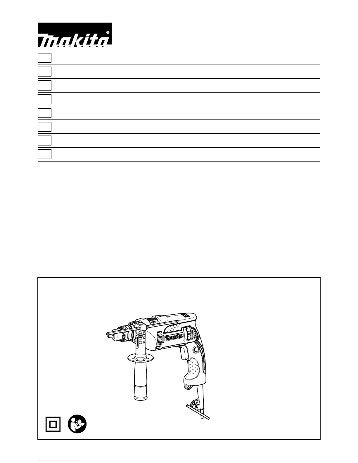
Makita HP1641F, HP1640F, HP1641 Instruction Manual
1
GB
Hammer Drill INSTRUCTION MANUAL
S
Slagborrmaskin BRUKSANVISNING
N
Borhammer BRUKSANVISNING
FIN
Iskuporakone KÄYTTÖOHJE
LV
Triecienurbjmašīna LIETOŠANAS INSTRUKCIJA
LT
Smūginis gręžtuvas NAUDOJIMO INSTRUKCIJA
EE
Lööktrell
KASUTUSJUHEND
RUS
Ударная дрель
РУКОВОДСТВО ПО ЭКСПЛУАТАЦИИ
HP1640
HP1640F
HP1641
HP1641F
2
1
2
1 009238
1
2 009245
1
A
B
3 009239
1
4 009240
1
5 009241
1
6 009242
1
2
7 009246
1
2
3
8 009243
9 009244
1
10 001302
3
ENGLISH (Original instructions)
Explanation of general view
1-1. Switch trigger
1-2. Lock button
2-1. Lamp
3-1. Reversing switch
4-1. Action mode changing lever
5-1. Side grip
6-1. Chuck key
7-1. Sleeve
7-2. Ring
8-1. Depth gauge
8-2. Side grip
8-3. Grip base
10-1. Blow-out bulb
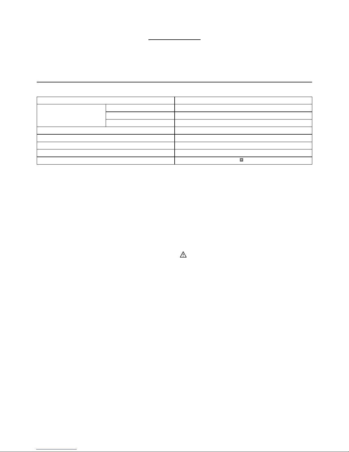
SPECIFICATIONS
Model HP1640/HP1640F/HP1641/HP1641F
Concrete 16 mm
Steel 13 mm
Capacities
Wood 30 mm
No load speed (min-1) 0 - 2,800
Blows per minute 0 - 44,800
Overall length 303 mm
Net weight 2.0 kg
Safety class /II
• Due to our continuing program of research and development, the specifications herein are subject to change without notice.
• Specifications may differ from country to country.
• Weight according to EPTA-Procedure 01/2003
ENE039-1
Intended use
The tool is intended for impact drilling in brick, concrete
and stone as well as for drilling without impact in wood,
metal, ceramic and plastic.
ENF002-1
Power supply
The tool should be connected only to a power supply of
the same voltage as indicated on the nameplate, and
can only be operated on single-phase AC supply. They
are double-insulated in accordance with European
Standard and can, therefore, also be used from sockets
without earth wire.
For Model HP1640,HP1641,HP1641F
ENG102-3
Noise
The typical A-weighted noise level determined according
to EN60745:
Sound pressure level (L
pA
) : 92 dB (A)
Sound power level (L
WA
) : 103 dB (A)
Uncertainty (K) : 3 dB (A)
Wear ear protection
ENG203-2
Vibration
The vibration total value (tri-axial vector sum)
determined according to EN60745:
Work mode: impact drilling into concrete
Vibration emission (a
h,ID
) : 19 m/s
2
Uncertainty (K) : 2.0 m/s
2
ENG301-1
Work mode : drilling into metal
Vibration emission (a
h,D
) : 2.5 m/s
2
Uncertainty (K) : 1.5 m/s
2
ENG901-1
•
The declared vibration emission value has been
measured in accordance with the standard test method
and may be used for comparing one tool with another.
• The declared vibration emission value may also be
used in a preliminary assessment of exposure.
WARNING:
•
The vibration emission during actual use of the power
tool can differ from the declared emission value
depending on the ways in which the tool is used.
• Be sure to identify safety measures to protect the
operator that are based on an estimation of
exposure in the actual conditions of use (taking
account of all parts of the operating cycle such as
the times when the tool is switched off and when it
is running idle in addition to the trigger time).
ENH101-17
For European countries only
EC Declaration of Conformity
Makita declares that the following Machine(s):
Designation of Machine:
Hammer Drill
Model No./ Type: HP1640,HP1641,HP1641F
Conforms to the following European Directives:
2006/42/EC
They are manufactured in accordance with the following
Standard or standardized documents:
EN60745
The Technical file in accordance with 2006/42/EC is
available from:
Makita, Jan-Baptist Vinkstraat 2, 3070, Belgium

4
31.12.2013
000331
Yasushi Fukaya
Director
Makita, Jan-Baptist Vinkstraat 2, 3070, Belgium
GEA010-1
General Power Tool Safety
Warnings
WARNING Read all safety warnings and all
instructions.
Failure to follow the warnings and instructions
may result in electric shock, fire and/or serious injury.
Save all warnings and instructions for
future reference.
GEB003-5
HAMMER DRILL SAFETY
WARNINGS
1. Wear ear protectors when impact drilling.
Exposure to noise can cause hearing loss.
2. Use auxiliary handle(s), if supplied with the
tool. Loss of control can cause personal injury.
3.
Hold power tool by insulated gripping surfaces,
when performing an operation where the cutting
accessory may contact hidden wiring or its own
cord.
Cutting accessory contacting a "live" wire may
make exposed metal parts of the power tool "live" and
could give the operator an electric shock.
4. Always be sure you have a firm footing.
Be sure no one is below when using the tool in
high locations.
5. Hold the tool firmly with both hands.
6. Keep hands away from rotating parts.
7. Do not leave the tool running. Operate the tool
only when hand-held.
8. Do not touch the bit or the workpiece
immediately after operation; they may be
extremely hot and could burn your skin.
9. Some material contains chemicals which may
be toxic. Take caution to prevent dust
inhalation and skin contact. Follow material
supplier safety data.
SAVE THESE INSTRUCTIONS.
WARNING:
DO NOT let comfort or familiarity with product (gained
from repeated use) replace strict adherence to safety
rules for the subject product. MISUSE or failure to follow
the safety rules stated in this instruction manual may
cause serious personal injury.
FUNCTIONAL DESCRIPTION
CAUTION:
• Always be sure that the tool is switched off and
unplugged before adjusting or checking function on
the tool.
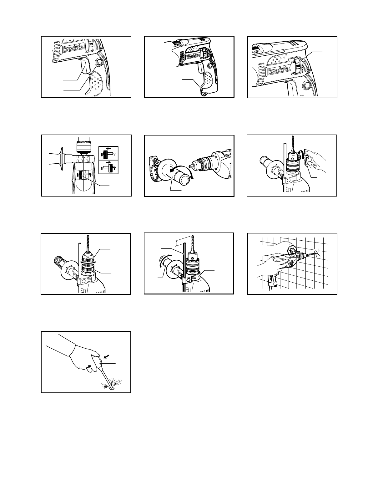
Switch action
Fig.1
CAUTION:
• Before plugging in the tool, always check to see
that the switch trigger actuates properly and
returns to the "OFF" position when released.
• Switch can be locked in "ON" position for ease of
operator comfort during extended use. Apply
caution when locking tool in "ON" position and
maintain firm grasp on tool.
To start the tool, simply pull the switch trigger. Tool
speed is increased by increasing pressure on the switch
trigger. Release the switch trigger to stop.
For continuous operation, pull the switch trigger and
then push in the lock button.
To stop the tool from the locked position, pull the switch
trigger fully, then release it.
Lighting up the lamps
For Model HP1640F,HP1641F
Fig.2
CAUTION:
• Do not look in the light or see the source of light
directly.
To turn on the lamp, pull the trigger. Release the trigger
to turn it off.
NOTE:
• Use a dry cloth to wipe the dirt off the lens of lamp.
Be careful not to scratch the lens of lamp, or it may
lower the illumination.
• Never use gasoline or thinner to clean the lens of
the lamp, or it will be damaged.
Reversing switch action
Fig.3
This tool has a reversing switch to change the direction
of rotation. Move the reversing switch to the
position
(A side) for clockwise rotation or the
position (B side)
for counterclockwise rotation.
CAUTION:
• Always check the direction of rotation before
operation.
• Use the reversing switch only after the tool comes
to a complete stop. Changing the direction of
rotation before the tool stops may damage the tool.
• If the switch trigger can not be depressed, check to
see that the reversing switch is fully set to
position
(A side) or (B side).

5
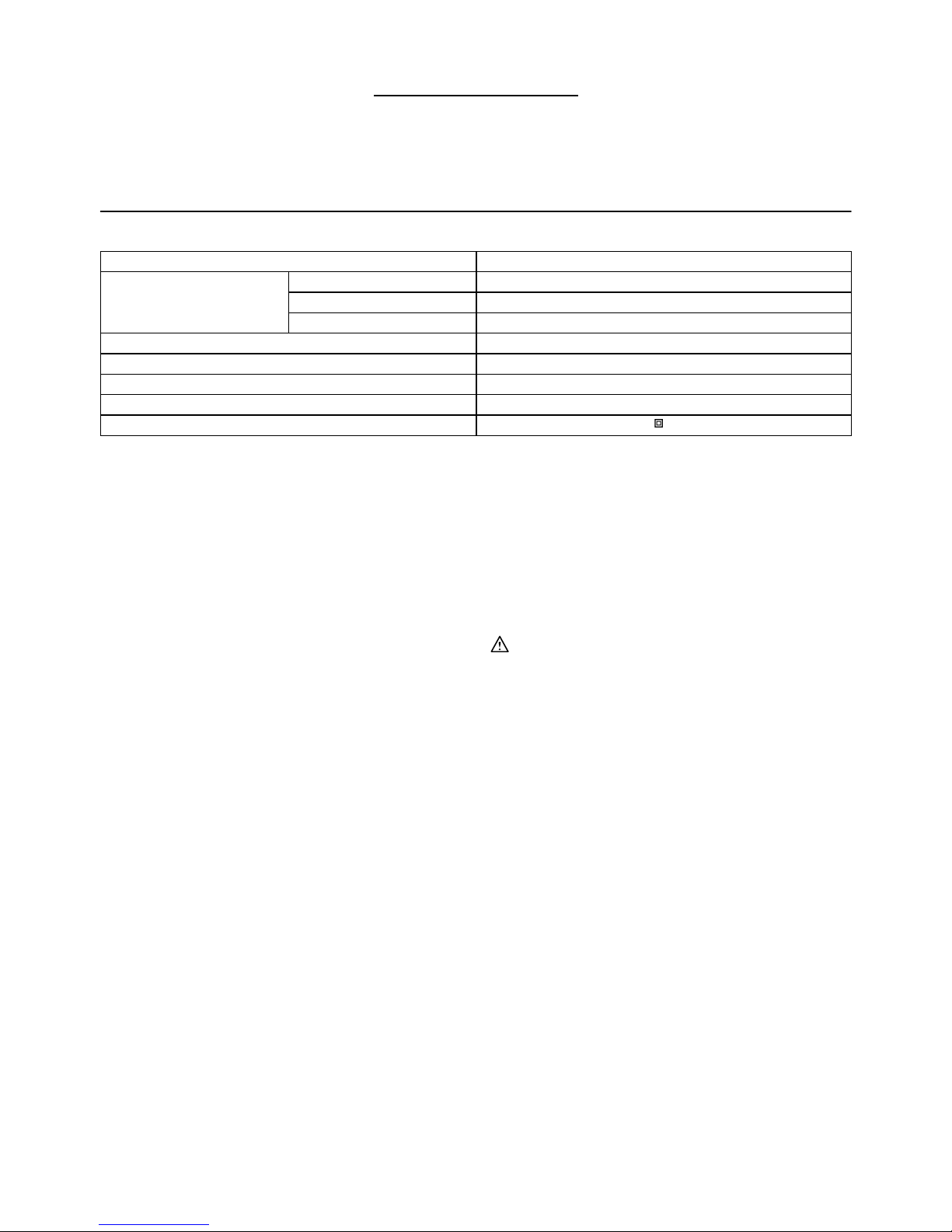
Selecting the action mode
Fig.4
This tool has an action mode change lever. For rotation
with hammering, slide the action mode change lever to
the right (
symbol). For rotation only, slide the action
mode change lever to the left (
symbol).
CAUTION:
• Always slide the action mode change lever all the
way to your desired mode position. If you operate
the tool with the lever positioned halfway between
the mode symbols, the tool may be damaged.
ASSEMBLY
CAUTION:
•
Always be sure that the tool is switched off and
unplugged before carrying out any work on the
tool.
Installing side grip (auxiliary handle)
Fig.5
Always use the side grip to ensure operating safety.
Install the side grip on tool barrel.
Then tighten the grip by turning clockwise securely at
the desired position. It may be swung 360° so as to be
secured at any position.
NOTE:
• The side grip cannot swing 360° when the depth
gauge is installed.
Installing or removing drill bit
For Model HP1640, HP1640F
Fig.6
To install the bit, place it in the chuck as far as it will go.
Tighten the chuck by hand. Place the chuck key in each
of the three holes and tighten clockwise. Be sure to
tighten all three chuck holes evenly.
To remove the bit, turn the chuck key counterclockwise
in just one hole, then loosen the chuck by hand.
After using the chuck key, be sure to return to the
original position.
For Model HP1641, HP1641F
Fig.7
Hold the ring and turn the sleeve counterclockwise to
open the chuck jaws. Place the bit in the chuck as far as
it will go. Hold the ring firmly and turn the sleeve
clockwise to tighten the chuck.
To remove the bit, hold the ring and turn the sleeve
counterclockwise.
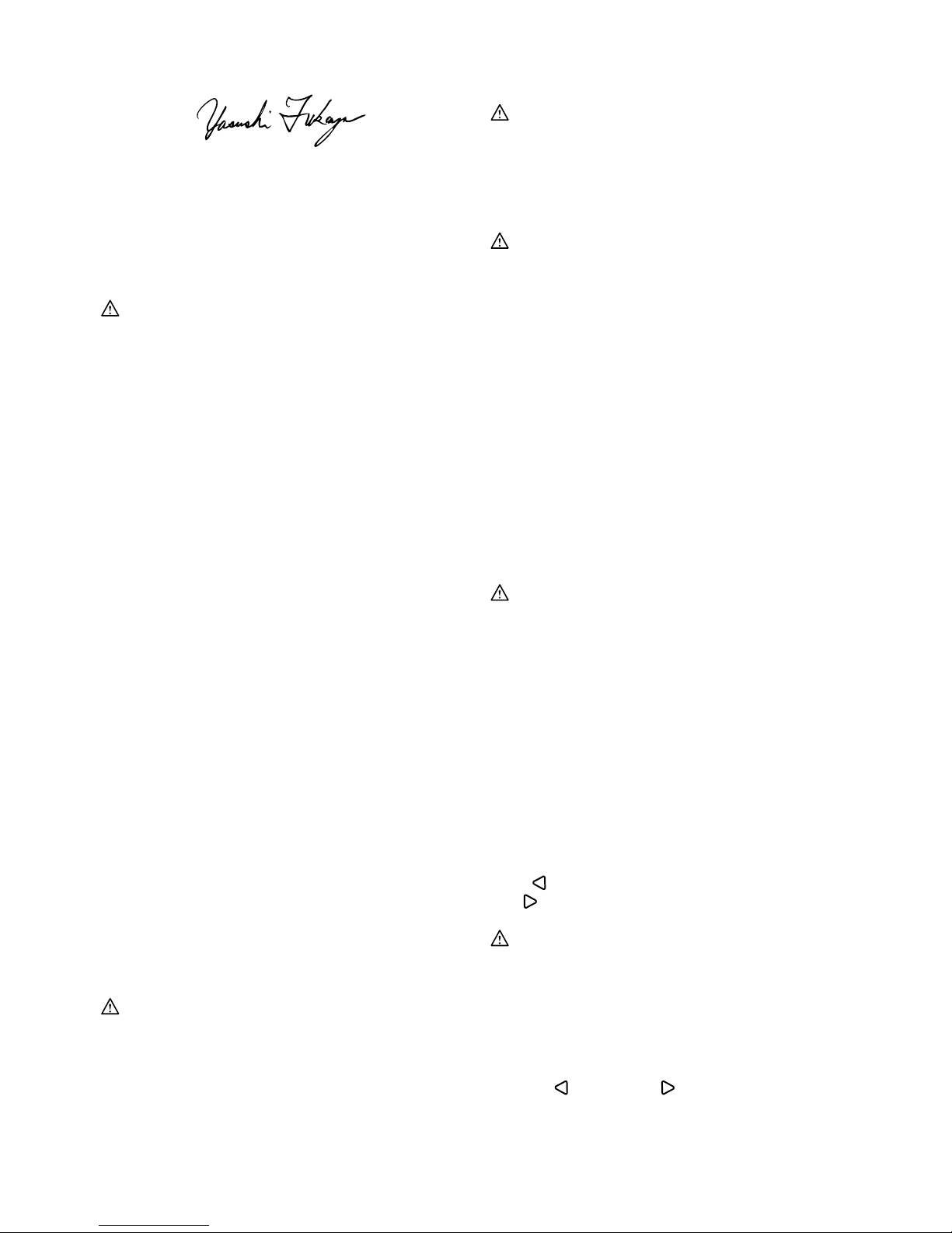
Depth gauge
Fig.8
The depth gauge is convenient for drilling holes of
uniform depth. Loosen the side grip and insert the depth
gauge into the hole in the side grip. Adjust the depth
gauge to the desired depth and tighten the side grip.
NOTE:
•
The depth gauge cannot be used at the position where
the depth gauge strikes against the tool body.
OPERATION
Hammer drilling operation
Fig.9
CAUTION:
• There is a tremendous and sudden twisting force
exerted on the tool/bit at the time of hole
break-through, when the hole becomes clogged
with chips and particles, or when striking
reinforcing rods embedded in the concrete. Always
use the side grip (auxiliary handle) and firmly hold
the tool by both side grip and switch handle during
operations. Failure to do so may result in the loss
of control of the tool and potentially severe injury.
When drilling in concrete, granite, tile, etc., move the
action mode changing lever to the position of
symbol
to use "rotation with hammering" action.
Be sure to use a tungsten-carbide tipped bit.
Position the bit at the desired location for the hole, then
pull the switch trigger. Do not force the tool. Light
pressure gives best results. Keep the tool in position and
prevent it from slipping away from the hole.
Do not apply more pressure when the hole becomes
clogged with chips or particles. Instead, run the tool at
an idle, then remove the bit partially from the hole. By
repeating this several times, the hole will be cleaned out
and normal drilling may be resumed.
Blow-out bulb (optional accessory)
Fig.10
After drilling the hole, use the blow-out bulb to clean the
dust out of the hole.
Drilling operation
When drilling in wood, metal or plastic materials, move
the action mode changing lever to the position
of
symbol to use "rotation only" action.
Drilling in wood
When drilling in wood, the best results are obtained with
wood drills equipped with a guide screw. The guide
screw makes drilling easier by pulling the bit into the
workpiece.
Drilling in metal
To prevent the bit from slipping when starting a hole,
make an indentation with a center-punch and hammer at
the point to be drilled. Place the point of the bit in the
indentation and start drilling.
Use a cutting lubricant when drilling metals. The
exceptions are iron and brass which should be drilled
dry.
CAUTION:
• Pressing excessively on the tool will not speed up
the drilling. In fact, this excessive pressure will only
serve to damage the tip of your bit, decrease the

6
tool performance and shorten the service life of the
tool.
• There is a tremendous force exerted on the tool/bit
at the time of hole break through. Hold the tool
firmly and exert care when the bit begins to break
through the workpiece.
• A stuck bit can be removed simply by setting the
reversing switch to reverse rotation in order to back
out. However, the tool may back out abruptly if you
do not hold it firmly.
• Always secure small workpieces in a vise or similar
hold-down device.
MAINTENANCE
CAUTION:
• Always be sure that the tool is switched off and
unplugged before attempting to perform inspection
or maintenance.
NOTICE:
• Never use gasoline, benzine, thinner, alcohol or
the like. Discoloration, deformation or cracks may
result.
To maintain product SAFETY and RELIABILITY, repairs,
carbon brush inspection and replacement, any other
maintenance or adjustment should be performed by
Makita Authorized Service Centers, always using Makita
replacement parts.
OPTIONAL ACCESSORIES
CAUTION:
• These accessories or attachments are
recommended for use with your Makita tool
specified in this manual. The use of any other
accessories or attachments might present a risk of
injury to persons. Only use accessory or
attachment for its stated purpose.
If you need any assistance for more details regarding
these accessories, ask your local Makita Service Center.
• Tungsten-carbide tipped hammer bit
• Hole saw
• Blow-out bulb
• Safety goggles
• Keyless drill chuck 13
• Chuck key
• Grip assembly
• Depth gauge
• Plastic carrying case
NOTE:
• Some items in the list may be included in the tool
package as standard accessories. They may differ
from country to country.

7
SVENSKA (Originalbruksanvisning)
Förklaring till översiktsbilderna
1-1. Avtryckare
1-2. Låsknapp
2-1. Lampa
3-1. Reverseringsknapp
4-1. Reglage för arbetsläge
5-1. Sidohandtag
6-1. Chucknyckel
7-1. Hylsa
7-2. Ring
8-1. Djupmätare
8-2. Sidohandtag
8-3. Griphandtag
10-1. Gummituta
SPECIFIKATIONER
Modell HP1640/HP1640F/HP1641/HP1641F
Cement 16 mm
Stål 13 mm
Kapacitet
Trä 30 mm
Obelastat varvtal (min-1) 0 - 2 800
Slag per minut 0 - 44 800
Längd 303 mm
Vikt 2,0 kg
Säkerhetsklass /II
• På grund av vårt pågående program för forskning och utveckling kan dessa specifikationer ändras utan föregående meddelande.
• Specifikationerna kan variera mellan olika länder.
• Vikt i enlighet med EPTA-procedur 01/2003
ENE039-1
Användningsområde
Maskinen är avsedd för slagborrning i tegel, cement och sten,
samt för borrning utan slag i trä, metall, keramik och plast.
ENF002-1
Strömförsörjning
Maskinen får endast anslutas till nät med spänning som
anges på typplåten och med enfasig växelström. Den är
dubbelisolerad i enlighet med europeisk standard och
får därför också anslutas till ojordade vägguttag.
För modell HP1640,HP1641,HP1641F
ENG102-3
Buller
Typiska A-vägda bullernivån är mätt enligt EN60745:
Ljudtrycksnivå (L
pA
) : 92 dB (A)
Ljudeffektnivå (L
WA
) : 103 dB (A)
Mättolerans (K): 3 dB (A)
Använd hörselskydd
ENG203-2
Vibration
Det totala vibrationsvärdet (treaxlig vektorsumma)
bestämt enligt EN60745:
Arbetsläge: slagborrning i cement
Vibrationsemission (a
h,ID
): 19 m/s
2
Mättolerans (K): 2,0 m/s
2
ENG301-1
Arbetsläge: borrning i metall
Vibrationsemission (a
h,D
) : 2,5 m/s
2
Mättolerans (K): 1,5 m/s
2
ENG901-1
•
Det deklarerade vibrationsemissionsvärdet har
uppmätts i enlighet med standardtestmetoden och kan
användas för jämförandet av en maskin med en annan.
• Det deklarerade vibrationsemissionsvärdet kan
också användas i preliminär bedömning av
exponering för vibration.
VARNING!
• Viberationsemissionen under faktisk användning
av maskinen kan skilja sig från det deklarerade
emissionsvärdet, beroende på hur maskinen
används.
•
Se till att hitta säkerhetsåtgärder som kan skydda
användaren och som grundar sig på en uppskattning
av exponering i verkligheten (ta med i beräkningen
alla delar av användandet såsom antal gånger
maskinen är avstängd och när den körs på tomgång
samt då startomkopplaren används).
ENH101-17
Gäller endast Europa
EU-konformitetsdeklaration
Makita försäkrar att följande maskiner:
Maskinbeteckning:
Slagborrmaskin
Modellnummer/Typ: HP1640,HP1641,HP1641F
Följer följande EU-direktiv:
2006/42/EC
De är tillverkade i enlighet med följande standard eller
standardiseringsdokument:
EN60745
Den tekniska dokumentationen i enlighet med
2006/42/EG finns tillgänglig från:
Makita, Jan-Baptist Vinkstraat 2, 3070, Belgium
8
31.12.2013
000331
Yasushi Fukaya
Direktör
Makita, Jan-Baptist Vinkstraat 2, 3070, Belgium
GEA010-1
Allmänna säkerhetsvarningar för
maskin
VARNING Läs igenom alla säkerhetsvarningar och
instruktioner.
Underlåtenhet att följa varningar och instruktioner
kan leda till elektrisk stöt, brand och/eller allvarliga personskador.
Spara alla varningar och instruktioner
för framtida referens.
GEB003-5
SÄKERHETSVARNINGAR FÖR
SLAGBORRMASKIN
1. Bär hörselskydd vid slagborrning. Kraftigt
buller kan orsaka hörselskador.
2. Använd extrahandtag, om det levereras med
maskinen. Att tappa kontrollen över maskinen
kan leda till personskador.
3.
Håll maskinen i de isolerade handtagen om det
finns risk för att skärverktyget kan komma i
kontakt med en dold elkabel eller sin egen kabel.
Om verktyget kommer i kontakt med en strömförande
ledning blir maskinens metalldelar strömförande och
kan ge operatören en elektrisk stöt.
4. Se till att du hela tiden har ett säkert fotfäste.
Se till att ingen står under dig när maskinen
används på hög höjd.
5. Håll maskinen stadigt med båda händerna.
6. Håll händerna på avstånd från roterande delar.
7. Lämna inte maskinen igång. Använd endast
maskinen när du håller den i händerna.
8. Rör inte vid borr eller arbetsstycke omedelbart
efter användning eftersom de kan vara extremt
varma och orsaka brännskador.
9.
Vissa material kan innehålla giftiga kemikalier. Se till
att du inte andas in damm eller får det på huden. Följ
anvisningarna i leverantörens materialsäkerhetsblad.
SPARA DESSA ANVISNINGAR.
VARNING!
GLÖM INTE att noggrant följa säkerhetsanvisningarna
för maskinen även efter det att du har blivit van att
använda den. OVARSAM hantering eller underlåtenhet
att följa säkerhetsanvisningarna i denna bruksanvisning
kan leda till allvarliga personskador.
FUNKTIONSBESKRIVNING
FÖRSIKTIGT!
• Se alltid till att maskinen är avstängd och
nätsladden urdragen innan du justerar eller
funktionskontrollerar maskinen.
Avtryckarens funktion
Fig.1
FÖRSIKTIGT!
• Innan du ansluter maskinen till elnätet ska du
kontrollera att avtryckaren fungerar och återgår till
läget "OFF" när du släpper den.
• Knappen kan låsas i läge "ON" för att underlätta
användning när maskinen används under längre
tid. Var försiktig när du låser maskinen i läge "ON",
och fortsätt håll ett stadigt grepp i maskinen.
Tryck in avtryckaren för att starta maskinen. Hastigheten
ökas genom att trycka hårdare på avtryckaren. Släpp
avtryckaren för att stoppa den.
För oavbruten användning trycker du in avtryckaren och
därefter låsknappen.
Tryck in avtryckaren helt och släpp den sedan när du
inte längre vill använda det låsta läget.
Tända lamporna
För modellerna HP1640F och HP1641F
Fig.2
FÖRSIKTIGT!
• Titta inte in i ljuset eller direkt i ljuskällan.
Tryck in avtryckaren för att tända lampan. Släpp
avtryckaren för att släcka den.
OBS!
• Använd en torr trasa för att torka bort smuts från
lampglaset. Var försiktig så att inte lampglaset
repas eftersom ljuset då kan bli svagare.
• Använd aldrig bensin eller thinner för att rengöra
lampan eftersom det skadar den.
Reverseringsknappens funktion
Fig.3
Denna maskin har en reverseringsknapp för byte av
rotationsriktning. Tryck reverseringsknappen till
läget
(A-sidan) för medurs rotation eller till
läget
(B-sidan) för moturs rotation.
FÖRSIKTIGT!
• Kontrollera alltid rotationsriktningen före
användning.
• Använd endast reverseringsknappen när maskinen
stannat helt. Maskinen kan skadas om du byter
rotationsriktning medan den fortfarande roterar.
• Om avtryckaren inte går att trycka in, kontrollerar
du att reverseringsknappen är helt satt i
läge
(A-sidan) eller (B-sidan).

9
Välja arbetsläge
Fig.4
Arbetsläget väljs med hjälp av en knapp. För
slagborrning skjuts knappen för byte av arbetsläge åt
höger (
symbol). För endast rotation skjuts knappen
för byte av arbetsläge åt vänster (
symbol ).
FÖRSIKTIGT!
• Skjut alltid knappen mot rätt läge så längt det går.
Om du använder maskinen med knappen placerad
halvvägs mellan lägessymbolerna kan maskinen
skadas.
MONTERING
FÖRSIKTIGT!
• Se alltid till att maskinen är avstängd och
nätsladden urdragen innan maskinen repareras.
Montera sidohandtaget (hjälphandtag)
Fig.5
Använd alltid sidohandtaget av säkerhetsskäl. Montera
sidohandtaget på maskinhuset.
Dra sedan åt handtaget ordentligt genom att vrida
medurs till önskat läge. Det kan vridas 360° för att
kunna fästas i alla lägen.
OBS!
• Sidohandtaget kan inte svänga 360° när
djupmätaren är monterad.
Sätta i och ta ur borrbits
För modellerna HP1640 och HP1640F
Fig.6
Skjut in bitset i chucken så långt det går. Dra åt chucken
för hand. Placera chucknyckeln i något av de tre hålen
och dra åt medurs. Dra åt jämnt i alla de tre chuckhålen.
Vrid chucknyckeln moturs i endast ett hål när du ska ta
bort bitset och lossa sedan chucken för hand.
Sätt tillbaka chucknyckeln på sin plats när du har använt
den.
För modellerna HP1641 och HP1641F
Fig.7
Håll i ringen och vrid hylsan moturs för att öppna chucken.
Skjut in bitset i chucken så långt det går. Håll ringen i ett
stadigt grepp och vrid hylsan medurs för att dra åt chucken.
Håll i ringen och vrid hylsan moturs för att ta bort bitset.
Djupmätare
Fig.8
Djupmätaren är ett bekvämt hjälpmedel för att borra flera
hål med samma djup. Lossa sidohandtaget och sätt i
djupmätaren i sidohandtagets hål. Ställ in djupmätaren
på lämpligt mått och dra fast sidohandtaget.
OBS!
• Djupmåttet kan inte användas i det läge där det
slår emot maskinhuset.
ANVÄNDNING
Slagborrning
Fig.9
FÖRSIKTIGT!
•
Borret/maskinen utsätts för en plötslig och oerhört stor
vridande kraft vid hålgenomslaget, när hålet fylls av
spån och partiklar eller när du slår ner förstärkningar i
cement. Använd alltid sidohandtag (extrahandtag) och
håll maskinen stadigt med både sidohandtaget och
pistolhandtaget under användningen. I annat fall är det
lätt att förlora kontrollen över maskinen med risk för
allvarliga skador som följd.
För borrning i betong, granit, tegel etc. skall knappen för
byte av arbetsläge flyttas till läget med symbolen
för
att använda "slagborr".
Använd ett hårdmetallbits.
Placera bitset där hålet ska vara och tryck sedan på avtryckaren.
Forcera inte maskinen. Ett lätt tryck ger bäst resultat. Håll
maskinen på rätt plats och hindra den från att flyttas ur hålet.
Tryck inte hårdare när hålet fylls med spånor eller andra
partiklar. Kör istället maskinen på tomgång och ta ur bitset ur
hålet bit för bit. Genom att upprepa detta flera gånger rensas
hålet och normal borrning kan återupptas.
Gummituta (tillbehör)
Fig.10
Efter borrning av hålet används gummitutan för att blåsa
rent hålet.
Borrning
För borrning i trä, metall eller plastmaterial flyttar du
knappen för byte av arbetsläge till symbolen
för att
använda "rotation".
Borra i trä
Vid borrning i trä uppnår du bäst resultat om du använder ett
träborr med styrskruv. Styrskruven gör det enklare att borra
genom att den drar in borret i arbetsstycket.
Borra i metall
För att borret inte ska halka när du börjar borra kan du göra
ett märke med syl och hammare i punkten där hålet ska
borras. Placera borrets spets i sylhålet och börja borra.
Använd ett smörjmedel vid borrning i metall.
Undantagen är järn och mässing som ska borras torrt.
FÖRSIKTIGT!
• Borrningen går inte fortare för att du trycker
hårdare på maskinen. Detta extra tryck skadar
bara toppen på ditt borr, sänker maskinens
prestanda och förkortar maskinens livslängd.
•
Det utvecklas en enorm kraft på maskinen/borret vid
hålgenomslaget. Håll ett stadigt tag i maskinen och var
försiktig när borret börjar tränga igenom arbetsstycket.
•
Ett borr som fastnat kan enkelt backas ur genom att
reversera borrningens rotationsriktning. Maskinen kan
dock backa för häftigt om du inte håller ordentligt i den.
• Fäst alltid små arbetsstycken i ett städ eller
liknande infästningsenhet.

10
UNDERHÅLL
FÖRSIKTIGT!
• Se alltid till att maskinen är avstängd och
nätkabeln urdragen innan inspektion eller
underhåll utförs.
OBS:
• Använd inte bensin, thinner, alkohol eller liknande.
Missfärgning, deformation eller sprickor kan
uppstå.
För att upprätthålla produktens SÄKERHET och
TILLFÖRLITLIGHET bör reparationer, kontroll och
utbyte av kolborstar samt allt annat underhålls- och
justeringsarbete utföras av ett auktoriserat Makita
servicecenter och med reservdelar från Makita.
VALFRIA TILLBEHÖR
FÖRSIKTIGT!
• Dessa tillbehör och tillsatser rekommenderas för
användning tillsammans med den Makita-maskin
som denna bruksanvisning avser. Om andra
tillbehör eller tillsatser används kan det uppstå risk
för personskador. Använd endast tillbehören eller
tillsatserna för de syften de är avsedda för.
Kontakta ditt lokala Makita servicecenter om du behöver
ytterligare information om dessa tillbehör.
• Slagborrbits med hårdmetallspets
• Hålsåg
• Gummituta
• Skyddsglasögon
• Nyckellös borrchuck 13
• Chucknyckel
• Handtag
• Djupmätare
• Förvaringsväska av plast
OBS!
• Några av tillbehören i listan kan vara inkluderade i
maskinpaketet som standardtillbehör. De kan
variera mellan olika länder.
11
NORSK (originalinstruksjoner)
Oversiktsforklaring
1-1. Startbryter
1-2. Sperreknapp
2-1. Lampe
3-1. Reversbryter
4-1. Funksjonsvelgerspak
5-1. Støttehåndtak
6-1. Kjoksnøkkel
7-1. Mansjett
7-2. Ring
8-1. Dybdemåler
8-2. Støttehåndtak
8-3. Håndtakets fot
10-1. Utblåsningsballong
TEKNISKE DATA
Modell HP1640/HP1640F/HP1641/HP1641F
Betong 16 mm
Stål 13 mm
Kapasitet
Tre 30 mm
Hastighet uten belastning (min-1) 0 - 2 800
Slag per minutt 0 - 44 800
Total lengde 303 mm
Nettovekt 2,0 kg
Sikkerhetsklasse /II
• Som følge av vårt kontinuerlige forsknings- og utviklingsprogram kan de tekniske dataene endres uten ytterligere forvarsel.
• Tekniske data kan variere fra land til land.
• Vekt i henhold til EPTA-prosedyre 01/2003
ENE039-1
Riktig bruk
Verktøyet er beregnet på å brukes med slagbor i mur,
betong og sten, samt for boring uten slagbor i tre, metall,
keramikk og plast.
ENF002-1
Strømforsyning
Maskinen må bare kobles til en strømkilde med samme
spenning som vist på typeskiltet, og kan bare brukes
med enfase-vekselstrømforsyning. Det er dobbelt
verneisolert i samsvar med europeiske standarder, og
kan derfor også brukes i kontakter uten jordledning.
For modell HP1640,HP1641,HP1641F
ENG102-3
Støy
Typisk A-vektet lydtrykknivå er bestemt i henhold til
EN60745:
Lydtrykknivå (L
pA
) : 92 dB (A)
Lydeffektnivå (L
WA
) : 103 dB (A)
Usikkerhet (K): 3 dB (A)
Bruk hørselvern
ENG203-2
Vibrasjon
Den totale vibrasjonsverdien (triaksial vektorsum)
bestemt i henhold til EN60745:
Arbeidsmåte: slagboring i betong
Genererte vibrasjoner (a
h,ID
): 19 m/s
2
Usikkerhet (K): 2,0 m/s
2
ENG301-1
Arbeidsmåte: boring i metall
Genererte vibrasjoner (a
h,D
): 2,5 m/s
2
Usikkerhet (K): 1,5 m/s
2
ENG901-1
•
Den angitte verdien for de genererte vibrasjonene
er blitt målt i samsvar med standardtestmetoden
og kan brukes til å sammenlikne et verktøy med et
annet.
• Den angitte verdien for de genererte vibrasjonene
kan også brukes til en foreløpig vurdering av
eksponeringen.
ADVARSEL:
• De genererte vibrasjonene ved faktisk bruk av
elektroverktøyet kan avvike fra den oppgitte
vibrasjonsverdien, avhengig av hvordan verktøyet
brukes.
• Vær påpasselig med å finne sikkerhetstiltak som
beskytter operatøren, basert på en oppfatning av
risiko under faktiske bruksforhold (på bakgrunn av
alle sider ved brukssyklusen, som når verktøyet
slås av og når det går på tomgang, i tillegg til
oppstarten).
 Loading...