

Page 1
T
ECHNICAL INFORMATION
Models No.
Description
HP1630, HP1631
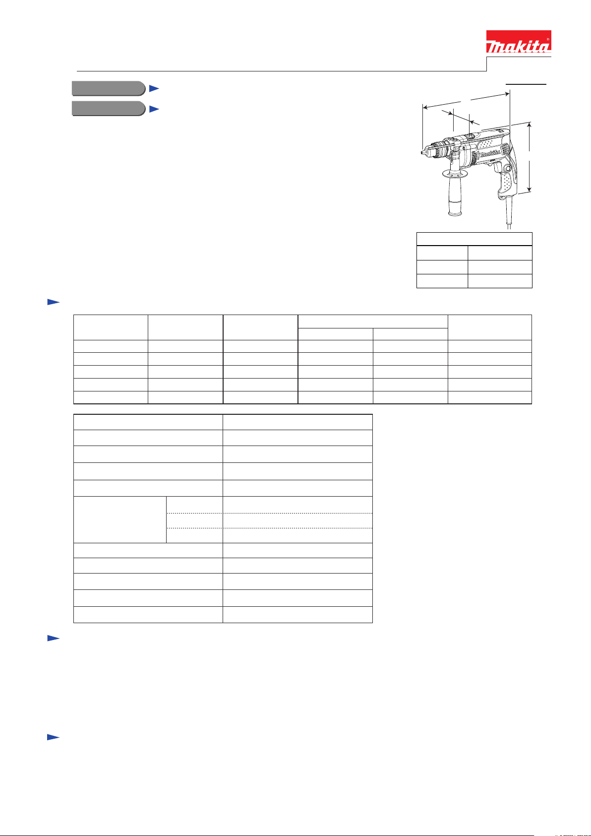
Hammer Drill 16 mm (5/8")
CONCEPT AND MAIN APPLICATIONS
Models HP1630 and HP1631 have been developed to surpass the competitors in
wattage, no load speed and impacts per minute.
Cylinder-shaped motor housing and aluminum gear housing cover provide
high performance.
Specification
PRODUCT
P 1/ 6
L
W
Dimensions: mm (")
Length (L) 296 (11-5/8)
Width (W)
Height (H)
75 (2-15/16)
204 (8)
H
Voltage (V) Cycle (Hz)
110
120
220
230
240
No load speed: min -1= rpm
Impacts per min: min -1= ipm
Drill chuck type
Chuck capacity: mm (")
Capacities: mm (")
Reversing switch
Protection against electric shock
Variable speed control by trigger
Power supply cord: m (ft)
Net weight: kg (lbs)
Current (A)
6.8
6.2
3.4
3.3
3.1
Concrete
Steel
Wood
50/60
50/60
50/60
50/60
50/60
Keyed chuck / Keyless Chuck
Continuous Rating (W)
Input Output
710
710
710
710
HP1630 / HP1631
0 - 3,200
0 - 48,000
1.5 - 13 (1/16 - 1/2)
16 (5/8)
13 (1/2)
30 (1-3/16)
Yes
Double insulation
Yes
2.0 (6.6)
1.9 (4.2)
---
420
420
420
420
420
Max. Output (W)
630
630
630
630
630
Standard equipment
Chuck key S-13 ........................ 1 (HP1630 only)
Key holder ................................. 1 (HP1630 only)
Depth gauge .............................. 1
Side grip .................................... 1
Plastic carrying case ................. 1 (K model only)
Note: The standard equipment for the tool shown above may differ by country.
Optional accessories
TCT drill bits
HSS metal drill bits
Wool bonnet 100
Rubber pad ass'y
Foam polishing pad 125
Page 2

Repair
CAUTION: Unplug the tool and remove the bit from the machine for safety before
repair/ maintenance in accordance with the instruction manual!
[1] NECESSARY REPAIRING TOOLS
DescriptionCode No. Use for
1R005 Retaining ring pliers RT-2N
1R026
Bearing Setting Pipe 16-8.2
Removing Retaining ring R-35
Removing Helical gear 37
P 2 / 6
1R028
1R035
1R037
1R045
1R139
1R223
1R224
1R269
1R283 Round bar for arbor 9-50
1R346
781024-2
781007-2 Wrench 14 Removing / Installing keyless Drill chuck
Bearing setting pipe 20-12.2
Bearing setting plate 15.2
Bearing setting plate 20.2
Gear extractor (large)
Drill chuck extractor
Torque wrench shaft 20-90N.m
Ratchet head 12.7
Bearing extractor
Center Attachment for 1R045
Wrench 43 Removing / Installing keyed Drill chuck
Installing Helical gear 37
Removing Helical gear 37
Removing/ Installing Armature
Removing / Installing Drill chuck
Removing Ball Bearings 607LLB and 608LLB
Removing Helical gear 37
Removing / Installing Drill chuck1R298 Hex. bar 10 with square socket
Removing/ Installing Armature
[2] LUBRICATION
Apply a little amount of molybdenum disulfide lubricant to the portions designated with the black triangle, and apply
Makita grease N. No.1 to the portion designated with the gray triangle to protect parts and product from unusual abrasion.
Fig. 1
Item No.
8
14
17
25
Description
Spindle
Helical gear 37 Cam portions
Pin 4 Drum portion
Armature
Drum portion where Ball bearing 6202DDW contacts
Drum portion where Gear housing cover contacts
Gear teeth where 12 Helical gear 37 contacts: 3g in total
Portion to lubricate
25
:Molybdenum disulfide lubricant
:Makita grease N No.1
8
Ball bearing 6202DDW
14
17
Gear housing cover
Page 3

Repair
[3] DISASSEMBLY/ASSEMBLY (cont.)
[3] -1. Armature
P 3 / 6
DISASSEMBLY
1) Remove Handle cover by loosening 4x18 Tapping screws, and then remove
Carbon brushes with Brush holders.
2) Remove Armature, Gear housing cover and Gear housing by loosening
4x30 Tapping screws and striking Motor housing with plastic hammer.
3) Drive the thread of 1R045 into 1R346 tightly, and set them to Gear housing
cover. (Fig. 2)
4) Remove Armature from Gear housing cover by turning the handle of 1R045.
5) Remove Ball bearings 607LLB and 608LLB of Armature with 1R269.
[3] DISASSEMBLY/ASSEMBLY
[3] -2. Drill Chuck
DISASSEMBLY
1) Hold 1R139 in vise.
2) Hold 1R298 with Drill chuck.
3) Fit the flat portions of Spindle to 1R139. (Fig. 3)
4) Turn Drill chuck counterclockwise with 1R298, 1R224 and 1R223. (Fig. 4)
Note: If Keyed drill chuck does not work, use 781024-2 to remove it.
If Keyless drill chuck does not work, hold the flat portions in vise and
fit 781007-2 into the flat portions of Spindle (Fig. 5), and then turn
Spindle clockwise.
Fig. 2
Thread of 1R045
1R346
Fig. 3
Flat portions of Spindle
1R139
Vise
Fig. 4
Fig. 5
Sleeve of Drill chuck
1R298
1R224
1R223
Flat portions of
Keyless drill chuck
DISASSEMBLY
Turn 1R223 clockwise to tighten Drill chuck to fastening torque 34.3 to 44.1 N.m.
Page 4

Repair
[3] DISASSEMBLY/ASSEMBLY
[3] -3. Helical Gear 37 and Ball Bearing 6202DDW
P 4 / 6
Fig. 6 Fig. 7
DISASSEMBLY
1) Remove Gear housing. Refer to page 3.
2) Remove Pin 4 and Steel ball 3.5 from Spindle to prevent
missing and breaking. (Fig. 6)
3) Hook awl to inner periphery of Ring spring 12 and remove
Ring spring 12. (Fig. 7)
4) Put Gear housing section on 1R037 and fit 1R026 to Spindle.
And then press Spindle slightly with arbor press. (Fig. 8)
5) Put 1R283 on Spindle and push out Spindle from Helical
gear 37 with arbor press. (Fig. 9)
Note: When Helical Gear 37 is removed from Spindle,
a heavy load arises in Ball bearing 6202DDW in Gear
housing section. Therefore, be sure to replace Ball bearing
6202DDW.
6) Remove Retaining ring R-35 in Bearing room, and remove
Ring 12 and Ring 19.
7) Remove Compression spring 16 from Spindle and insert
Compression spring in Ball bearing 6202DDW.
Strike Spindle top with plastic hammer, and Ball bearing
6202DDW can be removed from Gear housing.
Spindle
Fig. 8
1R026
Gear
housing
section
1R037
Fig. 9
1R283
Steel ball
3.5
Pin 4
Spindle
Awl
Helical gear 37
Ring spring 12
Spindle end
is put in
1R283.
Helical gear 37
ASSEMBLY
1) Complete assembling work to installation of Retaining ring
R-35 in the reverse order of the disassembling steps.
2) Mount Compression spring 16 on Spindle and put a little
amount of Molybdenum disulfide lubricant to Compression
spring 16, and then install them to Ball bearing 6202DDW.
3) Put Spindle on 1R035 and set 1R028 on Helical gear 37, and
then Press-fit Helical gear 37. (Fig. 10)
Fig. 10
1R028
1R035
Page 5

Circuit diagram
Fig. 11
Color index of lead wires' sheath
Black
White
Red
Orange
Purple
P 5 / 6
Brush holder
(far side from Switch)
6 4
1b
2a
2b
2 1
Brush holder
(near side from Switch)
3
5
1a
Noise suppressor
(if used)
Field
Switch
Page 6

Wiring diagram
Fig. 12
P 6 / 6
Route them between
Ribs A and B.
Field lead wire (white)
Field lead wire (red)
Fig. 13
Field lead wire (black )
Insulated terminal
1
Rib A
Rib B
Field lead wire
(black )
Rib C
2
Route them between
Ribs B and C.
When lead wires rise,
use Lead wire holder A
not to rise them.
Lead wire holder A
Lead wire holder B
1
Field lead wires (black, )
have to fixed with Lead wire
holder B.
2
Brush holder
Insulated terminal
Noise suppressor (if used)
 Loading...