

Page 1
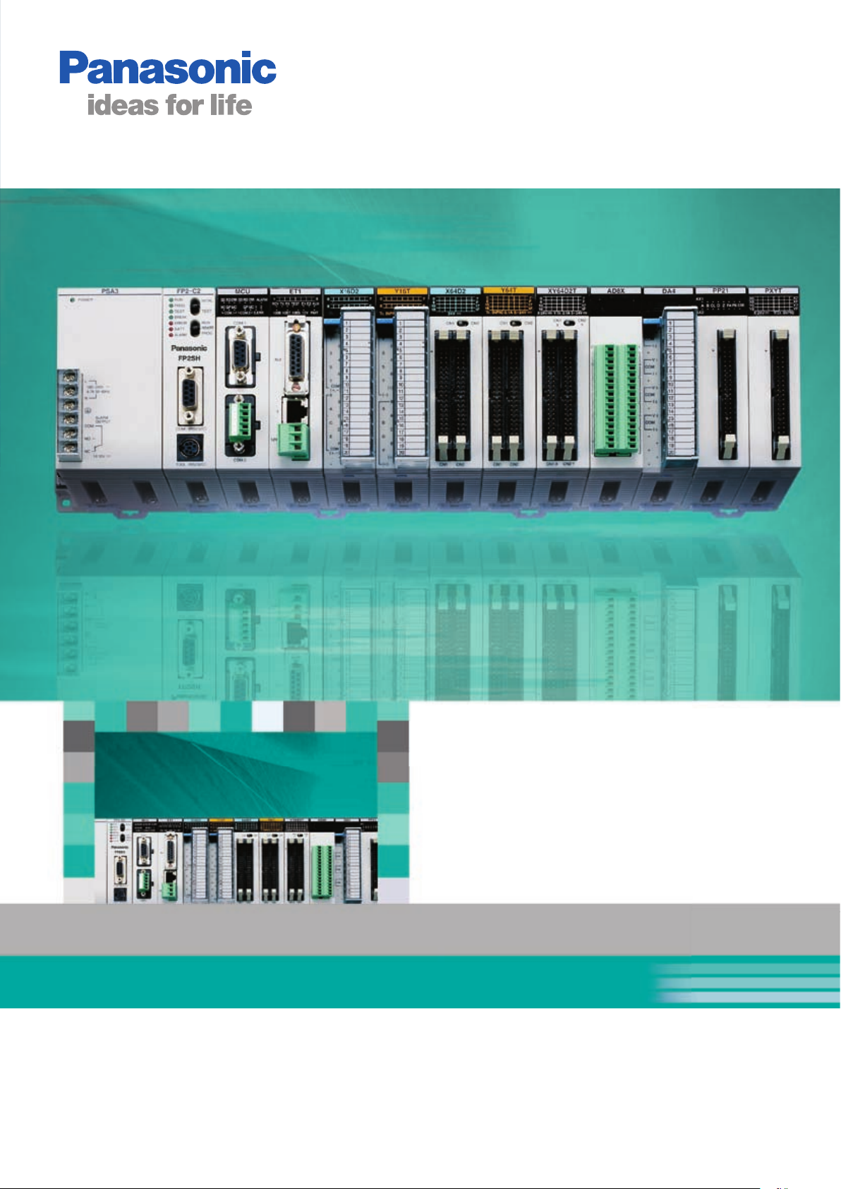
FP2/FP2SH Series
Programmable Controllers
09/2007
Page 2
CPU Units
09/2007
Top Performance, Full Range of Functions
CPU units
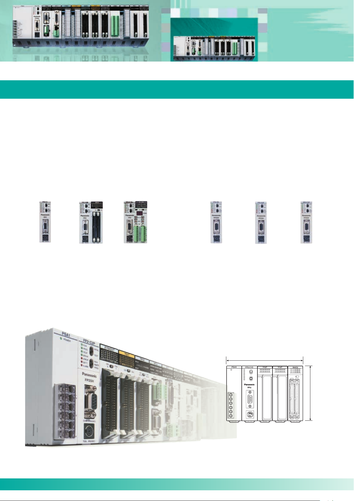
Selectable from six types, according to the application
There are six types of CPU units, including the standard type and the type with preinstalled commonly-used advanced functions.
This selection allows for more economical system development according to the application. See page 12 for details.
FP2
Superior cost performance
FP2SH
Industry‘s highest class processing speed
Adequate programming capacity
Standard type
FP2-C1
Body size
With 64 input points
FP2-C1D
With S-LINK
FP2-C1SL
60k step
standard type
FP2-C2
60k step type
for small PC card
FP2-C2P
120k step type
for small PC card
FP2-C3P
The front face is smaller than an A6 sheet of paper
The front face area is 140mm wide and 100mm high (when using five modules), which is small enough to fit completely on an
A6 sheet of paper. The compact body requires minimum installation space. (Depth: 108.3mm)
140mm
100mm
2
Page 3
Memory and I/O Control
09/2007
Flexible Expandability
Memory and I/O control
Equipped with an adequate program memory and operating memory capacity
The body is compact; however, the standard program memory capacity of FP2/FP2SH is as large as 16k/60k steps, and when
optional memory is added, 32k/120k steps. A variety of operation memory types are also available. The maximum number of
controlled I/O points is 2,048 (2,048/8,192 for FP2/FP2SH when using remote I/O units), which is sufficient for medium-scale
control.
Addition of optional memory
FP2: Addition of optional memory to the CPU unit allows it
to store up to 32k program steps, provides it with the
clock/calendar function, and makes comment writing
possible.
FP2SH: An optional IC card can be used as program memory
or expanded data memory.
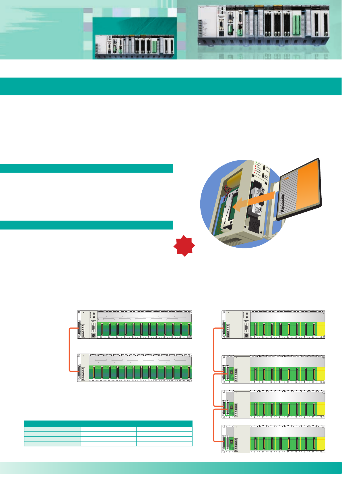
I/O point expansion by adding backplanes
See page 14 for details.
Optional memory
for FP2SH
NEW!
Conventional backplane
Only one backplane can be added to one master backplane.
When both the master and expansion backplanes are of the 14module type, up to 1,600 I/O points can be controlled.
CPU backplane
Expansion
cable
Max. number of backplanes 1 + 1 = 2 1 for master + 3 for expansion = 4
Max. number of units 12 + 13 = 25 8 + 8 x 3 = 32
Max. number of I/O points 25 x 64 = 1,600 32 x 64 = 2,048
Max. cable length 1 cable, 2m 3 cables, 3.2m
The H type and conventional type cannot be used in combination.
Expansion backplane
(The backplane can be used as either a master
or expansion backplane.)
Conventional type H type
Up to three backplanes can be added to one master backplane.
Now up to 32 units can be connected and up to 2,048 I/O points
controlled.
H type backplane
Master backplane (8 slots)
Expansion backplane (8 slots)
3
Page 4
4
Positioning
09/2007
Optimal Combination with Servo Drives
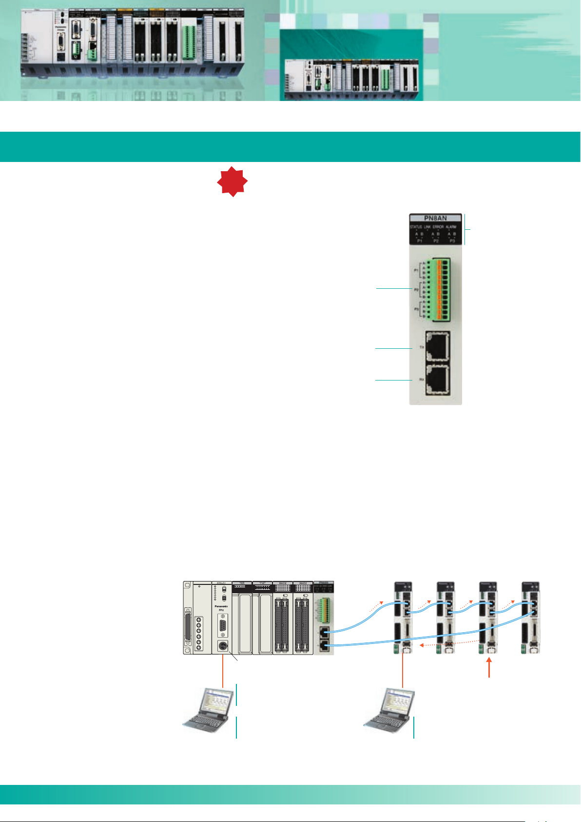
NEW!
"RTEX" positioning units
High-speed 100Mbps communications
Compatible with Realtime Express MINAS A4N*
network servo systems.
Facilitate multi-axis high precision positioning
High-accuracy multi-axis positioning control achieved
Monitoring LEDs
• Status indicator
• Link status
• Error indicator
• Pulser input status
by high-speed 100Mbps communication.
Compatible with commercially available LAN cables,
significantly reducing wiring costs.
Two-axis unit available in addition to the four- and
Pulser input
terminal
eight-axis units.
Data from a maximum of 600 points can be
registered for each axis.
Three-axis helical interpolation supported in addition
to two-axis linear and two-axis circular interpolation functions.
Dedicated tool software "Configurator PM" supports
operations from setup through startup and monitoring.
Equipped with a manual pulser input terminal,
allowing for fine teaching.
* Realtime Express and MINAS A4N are a trademark and a product name
of Matsushita Electric Industrial Co., Ltd.
Controls up to 256 axes, adequately supporting large-scale equipment control
Up to 32 eight-axis units can be connected and up to 256 axes controlled (when using FP2SH with H type backplane).
Selectable among two, four, and eight-axis types to flexibly support control system configurations of a few or multiple axes.
Use in combination with the ultra-high speed and large capacity FP2SH CPU unit (20k steps/1ms (measured by our company),
Network
(transmission) port
Network
(reception) port
2 axes: FP2-PN2AN
4 axes: FP2-PN4AN
8 axes: FP2-PN8AN
program capacity of 120k steps) adequately supports the control of large-scale equipment.
System configuration:
4
Maximum number of connectable
positioning units "RTEX"
FP2: 16 units FP2SH: 32 units
TOOL port of CPU unit
Dedicated tool software for
positioning units "RTEX"
Configurator PM
Programming tools
Control FPWIN GR
Control FPWIN Pro
Contact for inquiries about MINAS AC servomotor series: Panasonic Electric Works Europe AG
Telephone: +49 (0) 8024-648-0, Fax: +49 (0) 8024-648-111, www.panasonic-electric-works.com
Commercially
available LAN
cable
(Ethernet category 5e
shielded type)
One positioning unit can control two to
eight axes (depending on the type).
Servo amplifier: MINAS A4N manufactured by
Matsushita Electric Industrial Co., Ltd.
I/O signals of home position
proximity sensors, limit sensors, etc. are sent to A4N
Dedicated tool software for MINAS manufactured by Matsushita Electric Industrial Co., Ltd.
Panaterm
Page 5
Positioning
E
M
09/2007
High-Speed, High-Precision Positioning
Positioning units
High-speed, high-accuracy pulse output type positioning
unit. Speed command: 4Mpps, Startup time: 0.005ms
Support pulse-input type stepping motors, and servomotors. The speed
command range is up to 4Mpps, allowing for high-speed and high-accuracy
positioning. The startup time is as high as 0.005ms, allowing for a reduction
of the tact time. (Startup time: Time between reception of a command from a
CPU unit and pulse output from a positioning unit.)
The feedback pulse count function counts output pulses from encoders
or other devices.
The jog positioning function widens the supported application range.
The four types of S-curve acceleration/deceleration control allow for
smooth startup and stoppage.
Program libraries for linear interpolation and other operations
are available.
Function "Libraries for FPWIN Pro" can be downloaded from
our Website: www.panasonic-electric-works.com
Motor Driver I/F Terminal II is available for connection with MINAS AC
servo series.
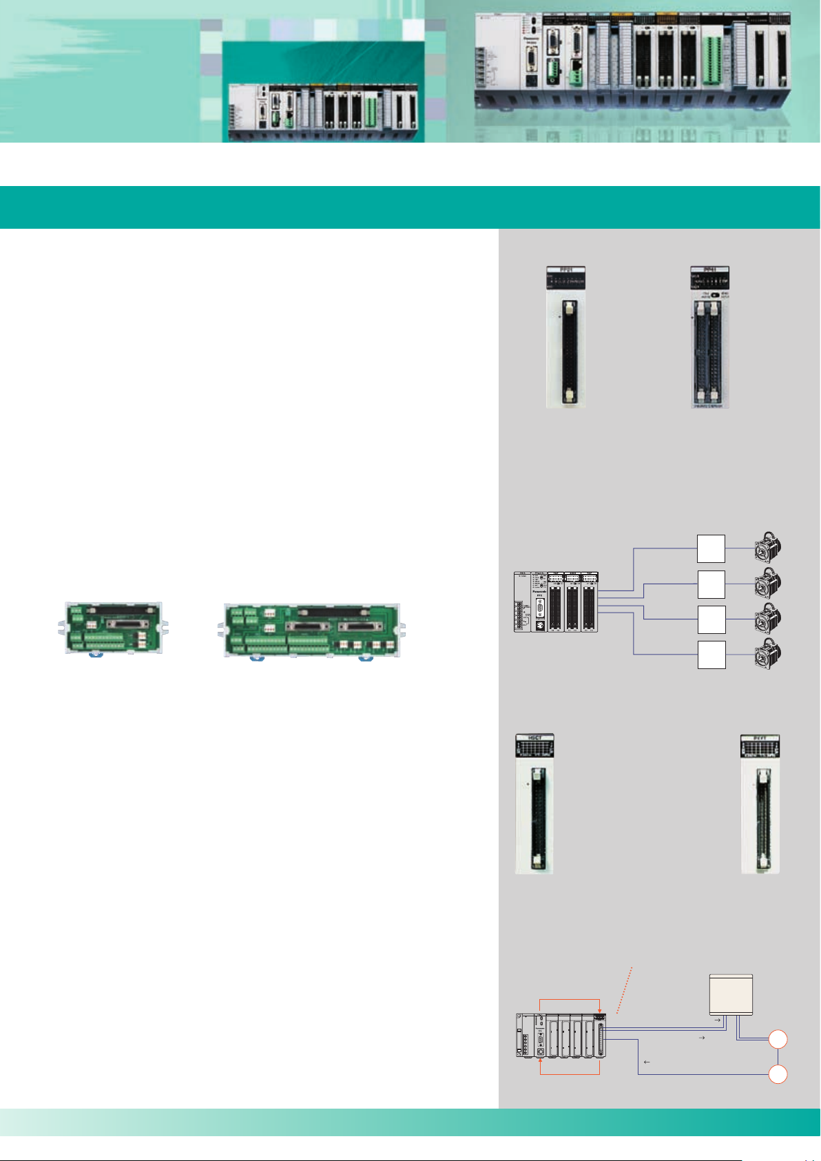
Positioning unit (2 axes) Positioning unit (4 axes)
FP2-PP21 FP2-PP22 FP2-PP41 FP2-PP42
Configuration
One unit can control up to 4 axes.
Motor
driver
Motor
driver
Motor
driver
For 1 axis (AFP8503) For 2 axes (AFP8504)
High-speed counter units and pulse I/O units
Interrupt, counting, pulse output, and PWM output
functions are integrated in a single unit
Equipped with four channels of a maximum of 200kHz high-speed
counter inputs, allowing for fine control.
Equipped with eight user-allocatable outputs for the four high-speed
counter channels. The number of counter stages can be changed.
Interrupt function can start interrupt program when the time specified
elapses or via external signal.
Control up to 100kpps pulse output and up to 30kpps PWM output.
A single module has high-speed counter, interrupt, general I/O, pulse
output*, PWM output* functions, allowing for highly efficient system
configuration.
* Only available with the pulse I/O units.
Motor
driver
Stepping motor
Servomotor
Pulse I/O units
FP2-PXYT(NPN)
FP2-PXYP(PNP)
High-speed counter units
FP2-HSCT(NPN)
FP2-HSCP(PNP)
Configuration
Counts RPM based on the encoder output, compares
the count with the preset RPM, and instructs the inverter to adjust the speed or stop operation.
Set conditions with the
F151 high-level instruction
Read data with the F150
high-level instruction
C=P Speed adjustment input
C>P Stoppage
input
Input the encoder output into the
phase input mode.
Inverter
5
Page 6
6
Analog Control
x
09/2007
Accurate Process Control
Analog control
Multi-range control of a variety of equipment is possible.
The units can be directly connected with thermocouples
and resistance temperature detectors
Support voltage/current/temperature sensor ranges
The analog input unit supports voltage, current, and temperature sensors.
The analog output unit supports voltage or current output.
Different voltage/current ranges can be controlled concurrently.
Equipped with multiple channels
The input unit has eight channels, and the output unit has four.
Space-saving multiple-channel control is possible.
High-speed conversion at 500ms by each channel
The speed of voltage and current input/output conversion can
reach as high as 500ms.
I/O refresh system
Since input/output data is allocated to the I/O memory, complicated
programming is not necessary.
Analog input units
Three types of analog input units are available to meet a wide variety of customer needs.
Laser analog sensor
Pressure sensor
Configuration
Analog input unit
Current input
Current input
Analog output unit
Voltage
output
(speed command)
Inverter
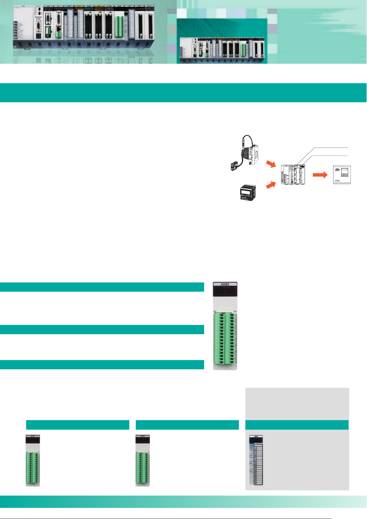
High-speed, high-accuracy, multiple-input unit with 8 isolated channels
Industry‘s fastest level
High-speed achieved by highly reliable isolation among channels
Temperature conversion: 20ms/ch
Voltage conversion: 5ms/ch
(Without insulation setting: 500ms/ch)
Industry‘s top level
High-accuracy conversion
Voltage: ±0.1% (25°C)
Temperature: ±0.3% (0 to 55°C)
Multiple inputs
A single unit supports inputs of
thermocouple, RTD, and voltage data*1.
8 inputs unit solely for
RTDs (Pt100/Pt1000)
High-speed, high-accuracy
Conversion speed: 20ms/ch
Conversion accuracy: ±0.3%
(0 to 55°C)
For users who input RTD data only
and require more affordable type.
8 low costs inputs solely
for voltage/current data
High-speed, high-accuracy
Low cost unit for input of voltage/
current data that indicates measurements of pressure, flow rate,
fluid volume, speed, etc.
FP2-AD8X
For users who require faster and more
accurate temperature control.
For users who require multiple isolated
input channels or who want to reduce
the cost per channel.
For users who want to input tempera
ture and voltage (current) data through
a single unit.
*
1: Current inputs can be converted into voltage in-
puts by attaching the supplied external resistor
to the input terminal section.
Analog output unit
Supports multiple channels.
(Four channels per unit).
High-speed, high-accuracy
Number of outputs: 4
Conversion speed: 500ms/ch
Overall accuracy: ±1.0% FS
or less
(0 to 55°C)
-
FP2-RTD
6
FP2-AD8VI
FP2-DA4
Page 7
Networking
09/2007
Connect all PLCs with Each Other
Support a wide variety of networks, such as open networks, PLC links, remote I/O systems,
and S-LINK
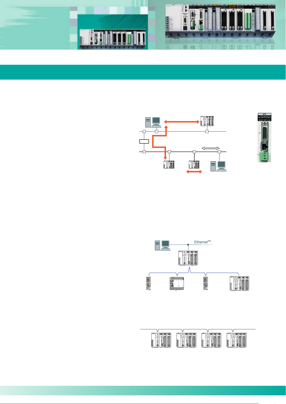
Open network
Ethernet
Supports three communication interfaces:
100BASE-TX, 10BASE-T, and 10BASE5.
Supports TCP/IP and UDP/IP.
Communication among a maximum of eight
connections is available.
Compatible with user-friendly MEWTOCOL.
Supports remote programming.
PLC link
PLC link is a system that allows our PLCs to share contact data and word data without programming.
Router
Computer link
LAN
Computer link Transparent communication function
Data transfer function
FP2-ET1
MEWNET-W0 mode
A PLC link of the compact high-performance PLC FPΣ (Sigma)* and FP-X* can be established by using a combination of the multicommunication unit and an RS485 communication block. This mode enables the efficient connection of FP2/FP2SH, FP
Σ (Sigma)
and FP-X units on a single network and contributes to significant cost reduction.
115.2kbps transmission speed.
Transfer of data of 64 points/128 words is possible.
Up to 16 units can be connected.
Extendable to 1,200m.
PLC link
(MEWNET-W0)
FPΣ (Sigma)
* Each FPΣ (Sigma) unit also requires an RS485 cassette (FPG-COM3 or FPG-COM4) to be attached.
* Each FP-X unit requires that an AFPX-COM3 or AFPX-COM4 communication cassette is attached.
FP-X
FP2/FP2SH
RS485 115.2kbps
Max. 16 stations/1,200m
FPΣ (Sigma) FP2/FP2SH
MEWNET-W2 mode
Large capacity PLC links can be established by using
twisted-pair cables and multi-wire link units.
500kbps transmission speed.
Transfer of data of 4096 points/4096 words is possible.
Up to 32 units can be connected.
Extendable to 1,200m
FP2
multi-wire
link unit
FP2
multi-wire
link unit
FP2
multi-wire
link unit
FP2
multi-wire
link unit
7
Page 8
8
Continuous Communication in Industrial Applications
Flexible Network Slave Unit
8
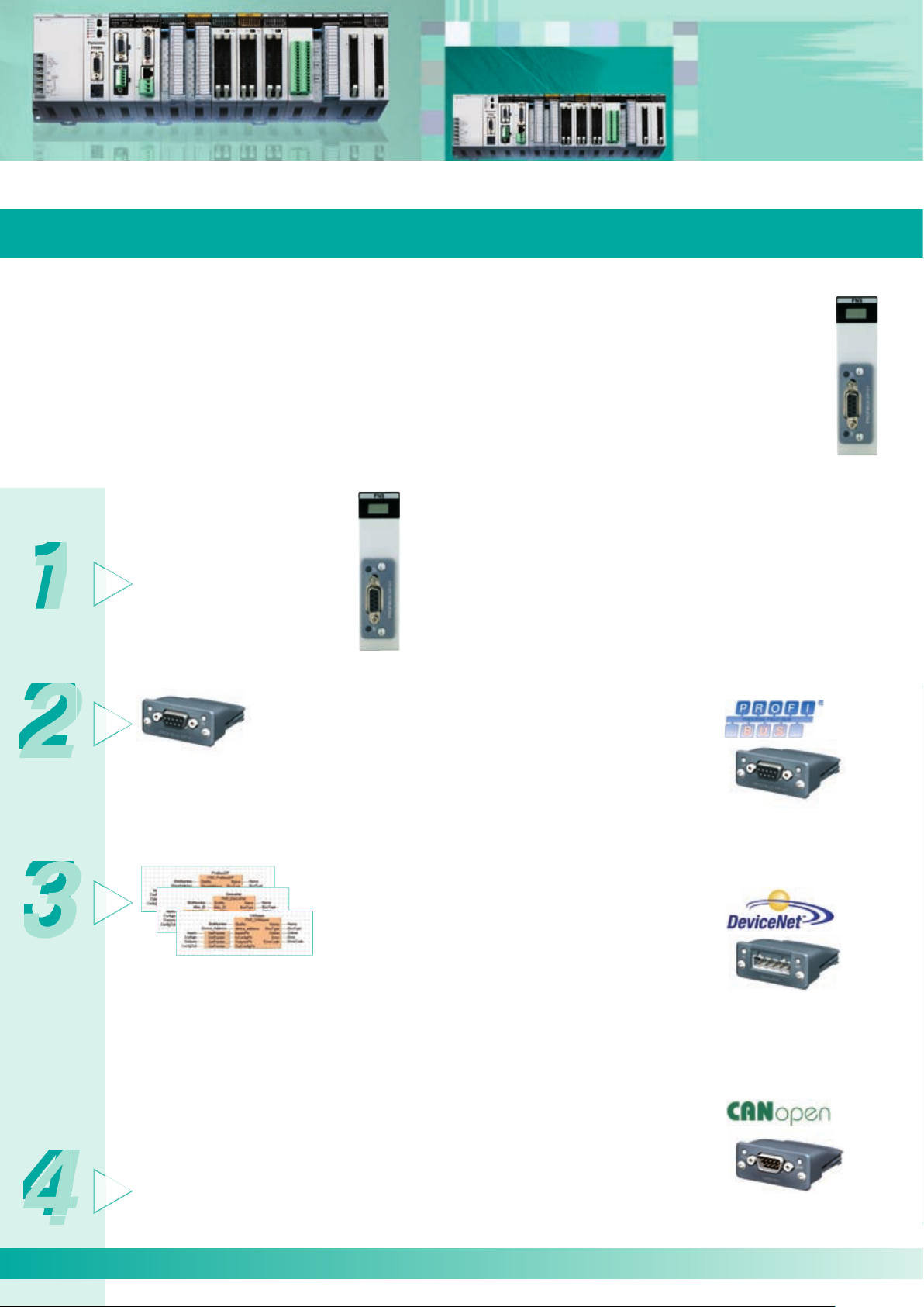
The Flexible Network Slave (FNS) unit is a powerful, modular network unit used together with the programmable controllers FP2 and FP2SH. By exchanging compact network blocks, you can connect to various networking systems
without having to modify your entire hardware platform. The blocks are available for three bus systems: PROFIBUS,
DeviceNet and CANopen. Others are planned for the future.
FP2-FNS
4 simple steps to
setup your network
Advantages:
Wide range of connectivity solutions.
One PLC hardware platform for several bus systems.
Fast reaction to new market networking trends possible with
existing units: no additional hardware development needed:
you need only exchange the network block.
Extremely compact.
Install the FP2 FNS expansion
module on the backplane of your
FP2 system. The number of units
is restricted by the size of the FP2
backplane.
PROFIBUS:
Automatic baud rate detection.
Transmission speed of 9.6kbps
to 12Mbps.
Max. link area of 76 words
(inputs and outputs).
Interface: DB9F
(9-pin Sub-D female).
PROFIBUS
Plug-in module
AFPN-AB6200
Various types of plug-in network blocks can be
mounted in the device at any phase between
ma nufacturer and end customer without having to
worry about special protective provisions.
For each network type, ready-made function libraries for FPWIN Pro are available free of charge
from the Panasonic Electric Works Europe AG
Website (www.panasonic-electric-works.com)
These libraries drastically shorten the time needed
to develop your applications, and consequently
save valuable human resource costs. They also
include a complete online help file and programming examples.
Download the GSD or EDS files with the description of the device from the Panasonic Electric
Works Europe AG Website.
The master unit requires these files to recognize
the slave device characteristics.
DeviceNet:
Automatic baud rate detection.
Transmission speed of 125kbps
to 500kbps.
Max. link area of 128 words in
each direction.
Interface: 5-pin terminal block.
DeviceNet
Plug-in module
AFPN-AB6201
CANopen:
Automatic baud rate detection.
Transmission speed of 10kbps
to 1Mbps.
Max. link area of 128 words
(for TPDOs and RPDOs).
Interface: 9-pin Sub-D mode
CANopen
Plug-in module
AFPN-AB6218
1
▲
▲
▲
2
▲
3
▲
4
▲
09/2007
Page 9

FP Web-Server
09/2007
The multifunctional FP Web-Server provides users with the option of connecting any FP Series PLC to the Internet/Intranet for
bi-directional communication via Ethernet. No changes to the PLC programs are necessary. Simply assign an IP address to the
FP Web-Server and connect the PLC to the FP Web-Server via the serial RS232C interface. A standard browser, e.g. MS Internet
Explorer, can be used for access at the PC. The Windows-based program FP Web Configurator Tool helps you easily set up and
configure the FP Web-Server.
The FP Web-Server´s 3 interfaces
100Base-TX / 10Base-T (RJ45, twisted pair)
– connects to the Ethernet at 100Mbit/s
RS232C (screw terminal)
– connects to the PLC at 1200 to 115.2kbit/s
RS232C (SUB-D 9 male)
– connects to a modem
FPWEB2
Highlights
Web-Server:
PLC data presented as HTML (or XML) pages
Access via standard Internet browser.
PLC data handling via HTML and Java Applet.
Optional: Password protection, IP lock security.
RS232C device server:
Ethernet <-> RS232C conversion (MEWTOCOL).
Transparent RS232C data tunneling via Ethernet.
Programming and visualization via TCP or UDP.
Modem dial-out / Internet system:
FP Web-Server can dial-out to the Internet.
Various Internet / GPRS system solutions.
FP Web-Server advantages
Uses existing Intranet, saves wiring.
Uses standard browser, saves Scada software.
Remote control.
Remote monitoring.
Remote programming.
Alarm information via e-mail.
Network time server synchronization:
PLC real-time clock update via NTP server.
E-mail
PLC can send e-mails.
E-mail via LAN e-mail server or Internet dial-up.
PLC-defined or pre-stored e-mail text.
PLC data array as attachment to an e-mail.
Modem dial-in / Ethernet gateway:
FP Web-Server can be dialed up via modem.
One remote gateway for multiple FP Web-Servers.
Modbus-TCP protocol:
Communication via standard industrial Ethernet
protocol (server and client).
Gateway for Modbus-RTU units (master and slave).
IEC 60870-5-101 and IEC 60870-5-104 protocol:
Communication via RS232C, RS485 adapter,
multipoint modem, dial-up modem, Ethernet.
Current consumption 65mA
Specifications
Operating voltage 24VDC (10.8-26.4VDC)
Communication interfaces
Communication protocol
Safety Passwords, IP lock
Ambient temp. 0°C to 55°C
Storage temp. -20°C to +70°C
Dimensions 25W x 90H x 60D (mm)
Weight 0.11kg
RS232C for connection to a PLC, RS232C for modem
connection, 100Base-TX/10Base-T, Ethernet
MEWTOCOL, DNS, HTTP, SMTP, FTP TELNET, TCP/IP, UDP/
IP, PPP, SNTP, Modbus
9
Page 10

10
Remote I/O Systems
1
2
3
4
5
6
7
8
9
0
1
2
3
4
5
6
7
8
9
0
MW
09/2007
Flexible Layout of I/O Devices
Remote I/O systems
MEWNET-F mode
The number of I/O points can be increased up to 8192 and the transmission distance can be extended up to 700m by using the
multi-wire link units.
MEWNET-F is a remote I/O system that connects I/O units in separate locations with twisted-pair cables.
The remote I/O master unit serves as a master station. Slave stations can be selected from the units shown on the next page.
Up to four wiring routes are available, allowing for a flexible layout of slave stations.
This network system is ideal for cases where I/O units need to be installed in separate locations or in a location away from the
control box.
F mode
Twisted-pair cables or VCTF cables
FP0
FP I/O terminal
board
FP2 multi-wire
link unit (F mode)
S-LINK
S-LINK is a link system that allows the free layout of I/O de-
control
unit
vices, such as sensors, by T-branch connections with a fourwire flat cable.
The number of I/O points can be increased up to 2048 in in
crements of one channel having 128 points.
A CPU unit with S-LINK ports and a single S-LINK unit are
available. FP2-C1SL has two S-LINK ports and can control
256 I/O points.
-
FP0
I/O link
unit
FPΣ
control
unit
FP0
I/O link
unit
FP I/O terminal unit
Manifold
solenoid valve
FP2/FP2SH FP2/FP2SH
S-LINK unit
S-LINK unit
FP2-SL2
Sensors to be connected by S-LINK must be chosen from among
S-LINK-compatible sensors manufactured by SUNX Limited.
10
S-LINK CPU unit
FP2-C1SL
Length: 200m max.
I/O points: 128 max.
T-branch
multi-drop
wiring
Two signal lines
Two power lines
Note: The number of I/O points may be less than 128 depending on the con-
nected device model and connection location. For details, refer to the
S-LINK instruction manual of SUNX Limited.
Page 11

Serial Communication
09/2007
Connect to Various Serial Devices
Serial communication control
The CPU units have an RS232C port as standard equipment. The communication unit enables
connections with RS232C/RS485/ RS422-compatible devices
CPU units
Multi-communication unit (MCU)
All CPU units have an RS232C port as standard
equipment. They can be directly connected to a host
computer or a display panel, and can also be connected to a modem to collect data from and change
programs in devices in a remote location.
Direct connection to a control panel or a computer
FP2
Display panel
RS232C port
Host computer
(commercially available PC)
The communication blocks are
detachable
Up to two blocks to be attached can be selected
among RS485, RS232C, and RS422 blocks.
Industry‘s
fastest
level
The 230kbps communication speed
(simultaneous two-channel communication) facilitates fast large-volume
data communications
Three communication blocks available.
FP2-MCU
Remote monitoring via a modem
Modem Public line Modem
Commercially
available cable
"PCWAY" for easy data collection
Special cable available
from Panasonic
The operation data
managing software
"PCWAY" allows
FP2/FP2SH operation
data to be imported into
Excel* without programming.
* Excel is a registered trademark
of the Microsoft Corporation.
FP2
RS232C RS422 RS485
FP2-CB232 FP2-CB422 FP2-CB485
The combination
is selectable
COM2 (the lower channel) is
sealed before shipping to
protect it from damage,
e. g. if only COM1 is used.
Multi-communication unit
FP2-MCU.
* This unit cannot operate
without a communication
block attached. Purchase
the above communication
block(s) together with this
unit.
11
Page 12

12
FP2
Power supply
Description
Item
Description
Item
Description
Item
Description
Item
Description
Item
Number of I/O points
Expansion
Operation speed
Built-in memory
Memory capacity
Internal relay
Timer/Counter (T/C)
Data register
0.35Ms/step (Basic instuction)
RAM (ROM is optional)
Approx. 16k steps
4048 points
1024 points in total
6000 words
Analog I/O
High-speed
counter
Pulse output
RS232C
port
Serial
Available by adding analog input
and analog output units
Available by adding high-speed
counter unit (max. 200kHz)
Positioning unit 2-axis
Positioning unit 4-axis
Standard equipped with CPU
unit
Expandable by adding C.C.U.,
M.C.U. and serial data unit
Expandable by adding M.C.U.
Available by adding high-speed
counter unit or pulse I/O unit
S-LINK,
MEWNET-F
MEWNET-W2 (Wire)
MEWNET-W0
PROFIBUS, DeviceNet,
CANopen
Linkable by using tool port or
COM. port on CPU unit. Also
available by adding M.C.U. and
C.C.U.
Available
Remote I/O
PLC Link
Computer Link
Modem connection
Program block-edit
during RUN
Constant scan
Clock/Calendar
function
100V to 120VAC / 200V to 240VAC /
100V to 240VAC, 24VDC
(varies with different models)
12V to 24VDC, 24VDC
pcommon
Relay 2A to 5A / Transistor 0.1A
to 0.5A
(varies with different models)
Input
Output
Interrupt input
Up to 768 points
Up to 1 backplane
Units: 25 max. I/O points: 1,600 max.
Remote I/O points: 2,048 max.
Up to 3 backplanes
Units: 32 max. I/O points: 2,048 max.
Remote I/O points: 2,048 max.
RS422
RS485
Operation
memory
H type
Standard
Available
Available
Can be used with the addition of
the calendar function option
Product numbers
Standard Type CPU
CPU with 64points input
CPU with S-LINK
FP2-C1
FP2-CS1D
FP2-C1SL
09/2007
Basic CPUs
The functions for a medium-scale PLC are squeezed into a compact body.
Perfect when combining various devices.
Features
1. Compact body
The functions for a medium-scale PLC are squeezed into a compact body which
requires minimal installation area (H: 100, W: 140, D: 108.3mm).
2. Module specifications enable flexible design
Backplanes for 5, 7, 9, 12, and 14 modules are available, and since the units have
the same width, you can choose the most economical design for your application.
3. RS232C port is standard
RS232C port allows connection with operation display panels and host computers,
as well as remote surveillance using modems, etc.
4. Different memory options are available to meet your application
Memory units for comment, calendar timer, expansion RAM, and ROM operation
are available so you can add just the options you need.
5. Dedicated instructions for high level data processing
Real number data operation is naturally supported, which simplifies programming.
Special functions Other built-in functions
12
Power supply/I/O specifications
Performance specifications
Special network functions
Page 13

FP2SH
Serial
Up to 1 backplane
Units: 25 max. I/O points: 1,600 max.
Remote I/O points: 8,192 max.
Up to 3 backplanes
Units: 32 max. I/O points: 2,048 max.
Remote I/O points: 8,192 max.
Power supply
Description
Item
Description
Item
Description
Item
Description
Item
Description
Item
Number of I/O points
Expansion
Operation speed
Built-in memory
Memory capacity
Internal relay
Timer/Counter (T/C)
Data register
File register
0.03Ms/step (Basic instuction)
RAM (ROM/Small PC card is optional)
Approx. 60k steps/approx. 120k
steps (varies with different models)
14,192 points
3072 points in total
10,240 words
32,765 words x 3 banks
Analog I/O
High-speed
counter
Pulse output
RS232C
port
Available by adding analog input
and analog output units
Available by adding high-speed
counter unit (max. 200kHz)
Positioning unit 2-axis
Positioning unit 4-axis
Standard equipped with CPU
unit
Expandable by adding C.C.U.,
M.C.U. and serial data unit
Expandable by adding M.C.U.
Available by adding high-speed
counter unit or pulse I/O unit
S-LINK,
MEWNET-F
MEWNET-W2 (Wire)
MEWNET-W0
MEWNET-VE
PROFIBUS
DeviceNet
CANopen
Linkable by using tool port or COM.
port on CPU unit. Also available by
adding M.C.U and C.C.U.
Available
Remote I/O
PLC Link
Computer Link
Modem connection
Program block-edit
during RUN
Constant scan
Clock/Calendar
function
100V to 120VAC / 200V to 240VAC /
100V to 240VAC, 24VDC
(varies with different models)
12V to 24VDC, 24VDC
pcommon
Relay 2A to 5A / Transistor 0.1A
to 0.5A
(varies with different models)
Input
Output
Interrupt input
Up to 768 points
RS422
RS485
Operation
memory
H type
Standard
Available
Available
Built-in type
Product numbers
Standard Type CPU (60k steps)
CPU for small PC card (60k steps)
CPU for small PC card (120k
steps)
FP2-C2
FP2-C2P
FP2-C3P
09/2007
High-Performance CPUs
Scanning time of 1ms for 20k steps. A high-performance model for high-speed operation.
Features
1. Scanning time of 1ms for 20k steps
An operating speed at the top of its class enables high-speed processing
and a dramatically decreased tact time.
2. Large programming capacity of up to 120k steps
60k and 120k programming capacities are available depending on the model.
3. Optional small PC card is also available
The small PC card is available for programming backup or data memory expansion. This allows great amounts of data to be processed.
4. Built-in comment and calendar timer functions
These functions, options with the FP2, are built right into the FP2SH.
The I/O unit and intelligent unit are the same for the FP2 series.
Special functions Other built-in functions
Power supply/I/O specifications
Performance specifications
Special network functions
13
Page 14

14
FP2/FP2SH
Power supply units
CPU units
FP2SH
Backplanes H type backplanes
100VAC,
2.5A type
FP2-PSA1
200VAC,
2.5A type
FP2-PSA2
100 to 240VAC,
5A type
FP2-PSA3
Standard type
FP2-C1
With 64-point input
FP2-C1D
With S-LINK
FP2-C1SL
Standard type
(60k steps)
FP2-C2
Expansion cable
(60cm)
FP2-EC
Expansion cable
(2m)
FP2-EC2
Dummy unit
FP2-DM
For small PC card
(60k steps)
FP2-C2P
For small PC card
(120k steps)
FP2-C3P
24VDC,
5A type
FP2-PSD2
(For use as both master and expansion backplanes. The 5-module
type cannot be used with or as an expansion backplane.)
5-module type
FP2-BP05
7-module type
FP2-BP07
9-module type
FP2-BP09
12-module type
FP2-BP12
14-module type
FP2-BP14
H type master backplane
(11 modules): 8 slots
FP2-BP11MH
H type expansion backplane
(10 modules): 8 slots
FP2-BP10EH
Type
Power supply unit, 5A type
CPU unit with 64 input points
CPU unit with S-LINK ports
Model No.
FP2-PSA3
FP2-PSD2
FP2-C1D
FP2-C1SL
FP2
Units that occupy two modules each
09/2007
Product Line and Accessories
FP2/FP2SH system configurations and unit lineup
Unit combinations
Most units occupy one slot, i. e. module each, though some units occupy two slots.
When selecting a backplane, carefully consider the units and number of slots you need.
The power supply unit and CPU unit must be mounted on the CPU backplane.
14
Page 15

FP2/FP2SH
Input and output units
Optional memories
For FP2SH
Type of memory unit
Analog input/output units
Positioning units
Multi-
communication
unit
Pulse input/
output units
Link-related units
FP2-EM1
FP2-EM2
F-ROM
FP2-EM4
EP-ROM
FP2-EM5
Analog output
unit
FP2-DA4
Data clear/
Data hold type
AFP8670/
AFP8671
Multi-communication unit
FP2-MCU
The communication blocks
are available separately.
Serial data unit
FP2-SDU
Computer
communication unit
FP2-CCU
Multi-wire link unit
FP2-MW
S-LINK
FP2-SL2
Flexible Network Slave
FP2-FNS
ET-LAN
FP2-ET1
Small PC card (2MB)
F-ROM
(AIC50020)
Small PC card (2MB)
SRAM
(AIC52000)
EP-ROM
(AFP5209)
Memory unit
with ROM socket
FP2-EM7 (AFP2207)
F-ROM
(AFP5208)
AFP8503
AFP8504
FP2-EM3
FP2-EM6
FP2-EM7
16-point DC input
FP2-X16D2
16-point NPN transistor output
FP2-Y16T
16-point PNP transistor output
FP2-Y16P
6-point Relay output (5A)
FP2-Y6R
16-point Relay output (2A)
FP2-Y16R
32-point DC input
FP2-X32D2
32-point NPN transistor output
FP2-Y32T
32-point PNP transistor output
FP2-Y32P
64-point DC input
FP2-X64D2
64-point NPN transistor output
FP2-Y64T
64-point PNP transistor output
FP2-Y64P
32-point input/32-point NPN output mixed
FP2-XY64D2T
FP2-XY64D7T
32-point input/32-point PNP output mixed
FP2-XY64D2P
FP2-XY64D7P
FP2-EM1
FP2-EM2
FP2-EM3
FP2-EM6
FP2-EM7
FP Memory Loader
FP2-PP21 FP2-PP22
Positioning units
FP2-PP41 FP2-PP42
Positioning units
FP2-PN2AN
Positioning units
RTEX
FP2-PN4AN
Positioning units
RTEX
FP2-PN8AN
Positioning units
RTEX
FP2-HSCT FP2-HSCP
High-speed counter
unit
FP2-PXYT FP2-PXYP
Pulse I/O
unit
1-axis type
2-axis type
Multiple analog
input unit
FP2-AD8X
Resistance thermometer
device input unit
FP2-RTD
Voltage/current
input unit
FP2-AD8VI
For FP2
(2-axis) (4-axis) (2-axis) (4-axis)(8-axis)
Serial data
control unit
Operation display
panel and computer
interface unit
Motor driver I/F
terminal II
Panasonic servo
MINAS AII/S series
Product
number
A
A
A
N/A
N/A
Comment
input
function
A
A
A
N/A
N/A
Clock/
calendar
function
N/A
A
A
A
N/A
With 16k
expansion
RAM
N/A
N/A
A
A
A
ROM
socket
A: Available
N/A: Not available
09/2007
Product Line and Accessories
Except for the 5-module expansion backplane, or backplanes can be expanded.
If the backplane is of the H type, up to three backplanes can be added.
Most of the units can be used in any combination; however, some combinations are subject to constraints due to the unit type,
current consumption, etc.
Please contact us for details.
15
Page 16

16
Xxxxx Xxxxxxxx
Xxxxx Xxxxxxxx
Control FPWIN Pro
Product numbers
With English manual
With German manual
With French manual
FPWINPROFEN5
FPWINPROFDE5
FPWINPROFFR5
Product numbers
With English manual
With German manual
With French manual
FPWINPROSEN5
FPWINPROSDE5
FPWINPROSFR5
09/2007
Programming According to the International Standard IEC 61131-3
FPWIN Pro is the Panasonic programming software developed according to the international standard IEC 61131-3 (for Windows 98,
NT V4.0, 2000, ME, XP or Vista). This new version is a result of experience gained over many years. We were one of the first PLC
manufacturers to offer an IEC 61131-3 programming software, and we are a leading member of the international organization
PLCopen.
Input and output variables
are defined once in the
global variable list
Functions can be saved in
libraries for future reuse
Navigator with tree representation of called functions provides an
overview even for very
complex projects
The SFC editor (Sequential Function Chart) allows you to easily
visualize processes
Structuring with
selection statements
Multiple address assigment
is caught automatically
by the compiler
Additional window for monitoring
and forcing variables
Using alliases names for PLC-independent
access on the special data registers, e.g. RTC
Type safe programming using
simple or complex data types
Special functions for controlling the
SFC program from another program
The ST editor (Structured
Text) solves complex programming tasks
Comfortable programming in the
graphical LD editor (ladder diagram)
One instruction for different
data types (overloaded instructions)
Long variable names make the
program self-explanatory
FPWINPro full version supports
all FP Series PLCs.
Using loops for running
through incoming data
Easy handling of
formulas and
arithmetic
expressions
The most important highlights at a glance:
16
Using STRING functions for analyzing incoming data...
...or for generating formatted output strings
One software for all FP Series PLCs.
5 programming languages (instruction list, ladder diagram, function block diagram,
sequential function chart, structured text) available for all PLCs.
Program organisation units, task and project management provide clear structure.
Reuse of ready-made functions and function blocks saves time for programming and debugging.
Online monitoring and diagnostics.
Forcing – Turning off input and output contacts via the PC.
Modem and Ethernet communication for remote programming, service and diagnostics.
Extensive comments – online documentation created hand in hand with the program.
6 languages are supported: English, German, French, Italian, Spanish and Japanese.
FPWINPro small version supports:
FP-e, FP0, FP-X, FPΣ (Sigma)
Free demonstration disc
Page 17

Other software tools
09/2007
FP OPC Server and FP Data Analyzer
FP OPC Server
Connects your favorite industrial application to FP2 or other FP Series PLCs
The Panasonic FP OPC Server allows high-performance data transfer between applications supporting the universally accepted
OPC PC DA Standard (v1-v3) and Panasonic FP Series PLCs. The FP OPC Server manages the device-specific communication and
provides data via a standard interface. Thus OPC clients connected to the server can exchange information with FP2 or other FP
Series PLCs.
Features of the FP OPC Server
Modern and intuitive user interface allows you to configure the
server. While creating the application, sophisticated user assistance helps
you in your work.
The server complies to the following OPC DA client/server technologies:
OPC DA 1.0a, 2.05a and 3.0.
The PLCs can be accessed via serial, modem and Ethernet communica
tion lines.
State-of-the-art import / export mechanism allows you to save, exchange
or edit data in XML format. Data can also be exchanged using a CSV file.
An icon or tool tip notifies the user about possible errors in configuration.
The FP OPC Server allows you to clearly structure your application,
e.g. by grouping elements in meaningful hierarchies.
Tolerant of interruptions due to optimized communication features.
-
FP OPC Server software with one license
Product number: AFPS03510D
FP OPC Server additional license
Product number: AFPS03517D
FP Data Analyzer
The FP Data Analyzer is a software tool for acquisition, logic analysis and
representation of recorded data on multiple channels connected to any Panasonic PLC. The software is a stand-alone tool. You need not install any other
software to run the FP Data Analyzer.
The FP Data Analyzer can be connected to the FP2 by utilizing the integrated
MEWNET Manager, for instance via the COM port. Recording and analyzing
remote PLCs via LAN or modem is just a matter of seconds.
The tool can be used for:
Performing failure diagnostics.
Finding and isolating failures.
Performing analyses, system optimization.
Documenting processes.
Shortening the time between setup and operation.
Carrying out machine maintenance.
Improving development.
FP Data Analyzer
Product number: AFPS04510D
17
Page 18

18
Xxxxx Xxxxxxxx
Xxxxx Xxxxxxxx
FP2-C2 FP2-C2P FP2-C3P
F-ROM/EP-ROM
Item
Available
Available
0.35µs or more
0.93µs or more
16k steps
32k steps
Max. 768 points
Max. 512 points
Max. 1600 points
Max. 2048 points
Max. 2048 points
4048 points
6000 words
0 to 143,333 words
(w/expansion 0 to 30,717 words)
256 words
F-ROM/EP-ROM
Optional memory unit
Optional memory unit
FP2 CPU unit FP2SH CPU unit
0.03µs or more
0.06µs or more
60k steps
Not available
120k steps
Not available
14,192 points
10,240 words
32,765 words x 3 banks
8448 words
Max. 768 points
Max. 512 points
Max. 1600 points
Max. 2048 points
Max. 8192 points
Small PC card (F-ROM/S-RAM)
−
5A max.
30VDC 1A
When the ALARM LED of CPU unit is lit
1c contact
Between input and ground terminals, 0.75mA or less
1500VAC for 1 minute (between input and ground terminals)
100 MΩ 500VDC (between input and ground terminals)
20,000 hours at 55°C
Built-in overcurrent protection
Built-in type
M3
Item
FP2-PSA1
100V - 120VAC
0.4A or less (at 100VAC)
85 to 132VAC
1 modul 1 modul 2 module 2 module
FP2-PSA2
200V - 240V
0.2A or less (at 200VAC)
47Hz ~ 63Hz
170 to 264VAC
FP2-PSA3
100V - 240VAC
0.7A or less (at 100VAC) 0.4A or less (at 200VAC)
30A or less (25°C)
85 to 264VAC
FP2-PSD2
24VDC
2.5A or less
10A or less
20.4 to 31.2VDC note)
40A or less (55°C)
2.5A max.
FP2-C1
FP2-C1D
FP2-C1SL
Operation speed
High-level
Built-in RAM
With expansion
With expansion
Conventional type
H type
Conventional type
H type
Link register
File register
Data register
Internal relay
With remote I/O
No expansion
Basic
Program capacity
Number of I/O points
Operation memory
Optional memory
Comment memory
Clock/Calendar function
Note: Allowable voltage fluctuation range after startup for the FP2-PSD2 is -35% to +30%. At startup, apply -15% to + 30% the rated voltage for 100ms or more.
Rated voltage
Current consumption
Surge current
Rated frequency
Operating
Voltage range
Input
Output
Alarm contact capacity
Alarm contact operation
Alarm contact type
Leakage current
Breakdown voltage
Insulation resistance
Guaranteed lifetime
Overcurrent protection function
Fuse
Terminal screw
Module size
FP2/FP2SH
09/2007
Specifications
CPU units
Power supply units
18
Page 19

FP2/FP2SH
Item
Rated load voltage
Max. load current
Max. surge current
OFF state leakage current
ON state maximum
voltage drop
Repose time
Power supply
for driving
internal circuit
Input points per common
Connection method
Voltage
Current
OFF→ON
ON→OFF
FP2-Y6R
5A 250VAC (10A/common)
5A 30VDC (10A/common)
Min. load: 100mA
10V (resistor load)
−
−
−
−
−
−
10ms or less
8ms or less
24VDC±10%
(21.6V to 26.4VDC)
70mA or less
2 points/common
Terminal block
(M3 screw)
FP2-Y16R
2A 250VAC (5A/common)
2A 30VDC (5A/common)
Min. load: 100µA
10V (resistor load)
−
−
−
−
−
−
10ms or less
8ms or less
24VDC±10%
(21.6V to 26.4VDC)
160mA or less
8 points/common
Terminal block
(M3 screw)
NPN open
collector
16-point type
FP2-Y16T
−
5-24VDC
0.5A (at 12 to 24VDC)
0.1A (at 5VDC)
3A 10ms or less
1µA or less
0.5V or less
0.1ms or less
0.3ms or less
4.75 to 26.4VDC
120mA
or less
(at 24VDC)
8 points/common
Terminal block
(M3 screw)
PNP open
collector
16-point type
FP2-Y16P
−
5-24VDC
0.5A (at 12 to 24VDC)
0.1A (at 5VDC)
3A 10ms or less
1µA or less
0.5V or less
0.1ms or less
0.3ms or less
4.75 to 26.4VDC
70mA
or less
(at 24VDC)
8 points/common
Terminal block
(M3 screw)
Relay output unit Transistor output unit
I/O mixed unit (output side)
NPN
open collector
FP2-Y32T
5-24VDC
0.1A (at 12 to 24VDC)
50mA (at 5VDC)
0.3A
1µA or less
1V or less
(at 6 to 26.4VDC)
0.5V or less
(at 6VDC or less)
0.1ms or less
0.3ms or less
4.75 to 26.4VDC
140mA
or less
(at 24VDC)
32 points/common
One 40-pin
connector
NPN
open collector
FP2-Y64T
5-24VDC
0.1A (at 12 to 24VDC)
50mA (at 5VDC)
0.3A
1µA or less
1V or less
(at 6 to 26.4VDC)
0.5V or less
(at 6VDC or less)
0.1ms or less
0.3ms or less
4.75 to 26.4VDC
250mA
or less
(at 24VDC)
32 points/common
Two 40-pin
connectors
PNP
open collector
FP2-Y32P
5-24VDC
0.1A (at 12 to 24VDC)
50mA (at 5VDC)
0.3A
1µA or less
1.5V or less
(at 6 to 26.4VDC)
0.5V or less
(at 6VDC or less)
0.1ms or less
0.3ms or less
4.75 to 26.4VDC
150mA
or less
(at 24VDC)
32 points/common
One 40-pin
connector
PNP
open collector
FP2-Y64P
5-24VDC
0.1A (at 12 to 24VDC)
50mA (at 5VDC)
0.3A
1µA or less
1.5V or less
(at 6 to 26.4VDC)
0.5V or less
(at 6VDC or less)
0.1ms or less
0.3ms or less
4.75 to 26.4VDC
270mA
or less
(at 24VDC)
32 points/common
Two 40-pin
connectors
FP2-XY64D2T
5-24VDC
0.1A (at 12 to 24VDC)
50mA (at 5VDC)
0.3A
1µA or less
1V or less
(at 6 to 26.4VDC)
0.5V or less
(at 6VDC or less)
0.1ms or less
0.3ms or less
4.75 to 26.4VDC
120mA
or less
(at 24 VDC)
32 points/common
Two 40-pin
connectors
FP2-XY64D2P
5-24VDC
0.1A (at 12 to 24VDC)
50mA (at 5VDC)
0.3A
1µA or less
1.5V or less
(at 6 to 26.4VDC)
0.5V or less
(at 6VDC or less)
0.1ms or less
0.3ms or less
4.75 to 26.4VDC
130mA
or less
(at 24 VDC)
32 points/common
Two 40-pin
connectors
Rated control capacity
6-point type 16-point type
− − − − − −
note 1)
note 2) note 2)
note 3) and 4)
DC input type/
Transistor output
(NPN) type
DC input type/
Transistor output
(PNP) type
Notes: The number of ON points that can be actuated simultaneously is limited by the input voltage and the ambient temperature.
The maximum load current is limited by the external power supply voltage.
1) The current capacity of each common terminal is 5A max.
2) The maximum load current of the transistor output unit is limited by the external power supply voltage.
3) The specifications also apply to the DC-input, transistor-output (NPN) type I/O-mixed unit with ON pulse catch input "FP2-XY64D7T".
4) The specifications also apply to the DC-input, transistor-output (PNP) type I/O-mixed unit with ON pulse catch input "FP2-XY64D7P".
FP2-C2 FP2-C2P FP2-C3P
F-ROM/EP-ROM
Item
Available
Available
0.35µs or more
0.93µs or more
16k steps
32k steps
Max. 768 points
Max. 512 points
Max. 1600 points
Max. 2048 points
Max. 2048 points
4048 points
6000 words
0 to 143,333 words
(w/expansion 0 to 30,717 words)
256 words
F-ROM/EP-ROM
Optional memory unit
Optional memory unit
FP2 CPU unit FP2SH CPU unit
0.03µs or more
0.06µs or more
60k steps
Not available
120k steps
Not available
14,192 points
10,240 words
32,765 words x 3 banks
8448 words
Max. 768 points
Max. 512 points
Max. 1600 points
Max. 2048 points
Max. 8192 points
Small PC card (F-ROM/S-RAM)
−
5A max.
30VDC 1A
When the ALARM LED of CPU unit is lit
1c contact
Between input and ground terminals, 0.75mA or less
1500VAC for 1 minute (between input and ground terminals)
100 MΩ 500VDC (between input and ground terminals)
20,000 hours at 55°C
Built-in overcurrent protection
Built-in type
M3
Item
FP2-PSA1
100V - 120VAC
0.4A or less (at 100VAC)
85 to 132VAC
1 modul 1 modul 2 module 2 module
FP2-PSA2
200V - 240V
0.2A or less (at 200VAC)
47Hz ~ 63Hz
170 to 264VAC
FP2-PSA3
100V - 240VAC
0.7A or less (at 100VAC) 0.4A or less (at 200VAC)
30A or less (25°C)
85 to 264VAC
FP2-PSD2
24VDC
2.5A or less
10A or less
20.4 to 31.2VDC note)
40A or less (55°C)
2.5A max.
Item
16-point DC input type
FP2-X16D2
12 - 24VDC
Approx. 8mA (at 24VDC)
Approx.
3kΩ
9.6V/4mA
2.5V/1mA
0.2ms or less
0.2ms or less
8 points/common
Terminal block (M3 screw)
32-point DC input type
FP2-X32D2
24VDC
Approx. 4.3mA (at 24VDC)
Approx.
5.6kΩ
19.2V/4mA
5.0V/1.5mA
0.2ms or less
0.3ms or less
32 points/common
One 40-pin connector
64-point DC input type
FP2-X64D2
24VDC
Approx. 4.3mA (at 24VDC)
Approx.
5.6kΩ
19.2V/4mA
5.0V/1.5mA
0.2ms or less
0.3ms or less
32 points/common
Two 40-pin connectors
FP2-XY64D2T
24VDC
Approx. 4.3mA (at 24VDC)
Approx.
5.6kΩ
19.2V/4mA
5.0V/1.5mA
0.2ms or less
0.3ms or less
32 points/common
Two 40-pin connectors
FP2-XY64D2P
24VDC
Approx. 4.3mA (at 24VDC)
Approx.
5.6kΩ
19.2V/4mA
5.0V/1.5mA
0.2ms or less
0.3ms or less
32 points/common
Two 40-pin connectors
I/O mixed unit (input side)DC input unit
OFF→ ON
ON→ OFF
FP2-C1
FP2-C1D
FP2-C1SL
Operation speed
High-level
Built-in RAM
With expansion
With expansion
Conventional type
H type
Conventional type
H type
Link register
File register
Data register
Internal relay
With remote I/O
No expansion
Basic
Program capacity
Number of I/O points
Operation memory
Optional memory
Comment memory
Clock/Calendar function
Note: Allowable voltage fluctuation range after startup for the FP2-PSD2 is -35% to +30%. At startup, apply -15% to + 30% the rated voltage for 100ms or more.
DC input type/Transistor output (NPN) type
DC input type/Transistor output (PNP) type
1) 2) 3)
Rated voltage
Current consumption
Surge current
Rated frequency
Operating
Voltage range
Input
Output
Alarm contact capacity
Alarm contact operation
Alarm contact type
Leakage current
Breakdown voltage
Insulation resistance
Guaranteed lifetime
Overcurrent protection function
Fuse
Terminal screw
Module size
Rated input voltage
Rated input current
Input impedance
Min. ON voltage/Min. ON current
Max. OFF voltage/Max. OFF current
Response
time
Input points per common
Connection method
(Either the positive or negative of the input power
supply can be connected to the common terminal.)
Notes: The number of ON points that can be actuated simultaneously is limited by the input voltage and the ambient temperature.
1) The specifications also apply to the input side of the CPU unit with 64 input points "FP2-C1D".
2) The specifications also apply to the DC-input, transistor-output (NPN) type I/O-mixed unit with ON pulse catch input "FP2-XY64D7T".
However, the response time is as follows: OFF→ ON: 0.2ms or less (X0-X1F); ON→ OFF: 0.3ms or less (X0-X1B), 1.0 to 5.0ms (X1C-X1F)
3) The specifications also apply to the DC-input, transistor-output (PNP) type I/O-mixed unit with ON pulse catch input "FP2-XY64D7P".
However, the response time is as follows: OFF→ ON: 0.2ms or less (X0-X1F); ON→ OFF: 0.3ms or less (X0-X1B), 1.0 to 5.0ms (X1C-X1F)
09/2007
Specifications
Input units
Output units
19
Page 20

20
Xxxxx Xxxxxxxx
Xxxxx Xxxxxxxx
Note 1: Current inputs can be converted into voltage inputs by attaching the supplied external resistor to the input terminal section.
Item
Rated load voltage
Max. load current
Max. surge current
OFF state leakage current
ON state maximum
voltage drop
Repose time
Power supply
for driving
internal circuit
Input points per common
Connection method
Voltage
Current
OFF→ON
ON→OFF
FP2-Y6R
5A 250VAC (10A/common)
5A 30VDC (10A/common)
Min. load: 100mA
10V (resistor load)
−
−
−
−
−
−
10ms or less
8ms or less
24VDC±10%
(21.6V to 26.4VDC)
70mA or less
2 points/common
Terminal block
(M3 screw)
FP2-Y16R
2A 250VAC (5A/common)
2A 30VDC (5A/common)
Min. load: 100µA
10V (resistor load)
−
−
−
−
−
−
10ms or less
8ms or less
24VDC±10%
(21.6V to 26.4VDC)
160mA or less
8 points/common
Terminal block
(M3 screw)
NPN open
collector
16-point type
FP2-Y16T
−
5-24VDC
0.5A (at 12 to 24VDC)
0.1A (at 5VDC)
3A 10ms or less
1µA or less
0.5V or less
0.1ms or less
0.3ms or less
4.75 to 26.4VDC
120mA
or less
(at 24VDC)
8 points/common
Terminal block
(M3 screw)
PNP open
collector
16-point type
FP2-Y16P
−
5-24VDC
0.5A (at 12 to 24VDC)
0.1A (at 5VDC)
3A 10ms or less
1µA or less
0.5V or less
0.1ms or less
0.3ms or less
4.75 to 26.4VDC
70mA
or less
(at 24VDC)
8 points/common
Terminal block
(M3 screw)
Relay output unit Transistor output unit
I/O mixed unit (output side)
NPN
open collector
FP2-Y32T
5-24VDC
0.1A (at 12 to 24VDC)
50mA (at 5VDC)
0.3A
1µA or less
1V or less
(at 6 to 26.4VDC)
0.5V or less
(at 6VDC or less)
0.1ms or less
0.3ms or less
4.75 to 26.4VDC
140mA
or less
(at 24VDC)
32 points/common
One 40-pin
connector
NPN
open collector
FP2-Y64T
5-24VDC
0.1A (at 12 to 24VDC)
50mA (at 5VDC)
0.3A
1µA or less
1V or less
(at 6 to 26.4VDC)
0.5V or less
(at 6VDC or less)
0.1ms or less
0.3ms or less
4.75 to 26.4VDC
250mA
or less
(at 24VDC)
32 points/common
Two 40-pin
connectors
PNP
open collector
FP2-Y32P
5-24VDC
0.1A (at 12 to 24VDC)
50mA (at 5VDC)
0.3A
1µA or less
1.5V or less
(at 6 to 26.4VDC)
0.5V or less
(at 6VDC or less)
0.1ms or less
0.3ms or less
4.75 to 26.4VDC
150mA
or less
(at 24VDC)
32 points/common
One 40-pin
connector
PNP
open collector
FP2-Y64P
5-24VDC
0.1A (at 12 to 24VDC)
50mA (at 5VDC)
0.3A
1µA or less
1.5V or less
(at 6 to 26.4VDC)
0.5V or less
(at 6VDC or less)
0.1ms or less
0.3ms or less
4.75 to 26.4VDC
270mA
or less
(at 24VDC)
32 points/common
Two 40-pin
connectors
FP2-XY64D2T
5-24VDC
0.1A (at 12 to 24VDC)
50mA (at 5VDC)
0.3A
1µA or less
1V or less
(at 6 to 26.4VDC)
0.5V or less
(at 6VDC or less)
0.1ms or less
0.3ms or less
4.75 to 26.4VDC
120mA
or less
(at 24 VDC)
32 points/common
Two 40-pin
connectors
FP2-XY64D2P
5-24VDC
0.1A (at 12 to 24VDC)
50mA (at 5VDC)
0.3A
1µA or less
1.5V or less
(at 6 to 26.4VDC)
0.5V or less
(at 6VDC or less)
0.1ms or less
0.3ms or less
4.75 to 26.4VDC
130mA
or less
(at 24 VDC)
32 points/common
Two 40-pin
connectors
Rated control capacity
6-point type 16-point type
Voltage
Current
Item
Item
Number of output points
Output range
(digital input)
Resolution
Conversion speed
Overall accuracy
Insulation method
Analog output
Analog output unit FP2-DA4
4 channels
±10V (K-2048 to K+2047)
0 to 20mA (K0 to K4095)
1/4096
500µs/ch
±1.0% F.S. or less (0 to 55°C)
– Between the output terminal and FP2 internal circuits: Photocoupler – Between channels: No insulation
Hold/Non-hold setting by shared memory setting
1. Analog input
2. Analog output
− − − − − −
note 1)
note 2) note 2)
note 3) and 4)
Number of input points
Voltage
Current
Thermocouple
R.T.D
Voltage
Current
Thermocouple
R.T.D
Input range
(resolution)
Conversion
speed
Overall accuracy
Insulation method
Digital output
Broken wire sensing
Input range change method
Averaging
Offset setting
FP2-AD8X FP2-RTD FP2-AD8VI
±10V
1V ± 5V
±100mV
(1/65536)
(1/13107)
(1/65536)
S: 0 to +1500
°C
J: -200 to +750°C
J: -100 to +400°C
K: -200 to +1200°C
K: -200 to +1000°C
K: -200 to +600
°C
T: -200 to +350°C
R: 0 to +1500°C
N: -200 to +1300°C
(0.1
°C)
(0.1°C)
(0.1°C)
(0.1°C)
(0.1°C)
(0.1
°C)
(0.1°C)
(0.1°C)
(0.1°C)
Pt 100 : -200 to +650°C
Pt 100 : -100 to +200°C
JPt 100 : -200 to +650°C
JPt 100 : -100 to +200°C
JPt1000 : -100 to +100
°C
(0.1°C)
(0.1°C)
(0.1°C)
(0.1°C)
(0.1
°C)
500µs/ch (insulated), 5ms (insulated)
−
20ms/ch
20ms/ch
Voltage: ±0.1% FS (25 °C) Voltage temperature coefficient: ±0.3% (0 to 55 °C)
Between the input terminal and FP2 internal circuits: Photocoupler and DC/DC converter
Between the input terminal and FP2 internal circuits: Photocoupler
Between channels: PhotoMOS relay
Selectable from 3 to 64 times for each channel (Moving average after cutting the maximum and minimum values)
Selectable from K -2048 to +2047 for each channel
Each channel (only when a thermocouple or RTD is inputted)
Each channel
Batch switching of all channels: By the range setting switch
Each channels: By shared memory setting
−
−
−
−
note1)
−
−
−
−
−
− −
−
20ms/ch
±0.3% F.S. (0 to 55°C)
500µs/ch
500µs/ch
±1.0% F.S. (0 to 55°C)
−
−
−
(1/65536)
(1/13107)
(1/32768)
(1/13107)
±
10V
1V to 5V
±20mA
4mA to 20mA
8 channels8 channels 8 channels
DC input type/
Transistor output
(NPN) type
DC input type/
Transistor output
(PNP) type
Notes: The number of ON points that can be actuated simultaneously is limited by the input voltage and the ambient temperature.
The maximum load current is limited by the external power supply voltage.
1) The current capacity of each common terminal is 5A max.
2) The maximum load current of the transistor output unit is limited by the external power supply voltage.
3) The specifications also apply to the DC-input, transistor-output (NPN) type I/O-mixed unit with ON pulse catch input "FP2-XY64D7T".
4) The specifications also apply to the DC-input, transistor-output (PNP) type I/O-mixed unit with ON pulse catch input "FP2-XY64D7P".
09/2007
FP2/FP2SH
Specifications
Analog I/O units
20
Page 21

FP2/FP2SH
Performance Specification
Transmission specifications for communication interface
−
−
−
−
−
−
Start-stop synchronization
−
−
−
−
RS232C RS485
Note 1: The protocol can be downloaded from: www.panasonic-electric-works.com
Specifications
Item
Item 100BASE-TX
Item
VE mode (PLC link) FL-net mode
* For FP2SH (Cannot be used for FP2)
1)
note 2) note 2)
note 3)
1)
1)
10BASE5 : 500m (2500m)
10BASE-T : 100m (500m)
FL-net [FA link protocol (UDP/IP)]
MEWTOCOL
Communication
interface
Communication speed
Cycle time
example
Cable length
Communication protocol
Link
communication
specifications
Message communication
specifications
Number of nodes
Other functions
Ethernet
10BASE5/10BASE-T
10Mbit/s
50ms/32 units
(2048 points/2048 words)
Link relay
8192 points/unit
Link register
8192 words/unit
2048 bytes max.
(Compatible with MEWTOCOL)
99 units max.
Data transfer
Remote programming
Multilevel link communications
1024 bytes max.
(Not compatible with MEWTOCOL)
254 units max.
Interconnection with other
companies' units
Communication
block used
Interface
Communication
method
Synchronization
Transmission line
Transmission distance
Transmission speed
(To be set in the system register)
Transmission code
Transmission format
(To be set in the system register)
Number of stations
PLC link capacity
COM1
(upper channel)
COM2
(lower channel)
Number of attachable units
Supported versions
General-purpose serial communications
Computer link
(Panasonic open protocol "MEWTOCOL" should be used.)
1:1 communications 1:N communications 1:1 communications 1:N communications
FP2-CB232
FP2-CB422
RS232C RS422
Full duplex
FP2-CB232
FP2-CB422
RS232C RS422
Full duplex
FP2-CB232
FP2-CB422
Three-core or
five-core shielded wire
15m Length: 1200m max.
300 to 230,400bps
Twisted-pair cable
or VCTF
Length: 1200m max.
300 to 230,400bps
(19,200 bps when our C-NET adapter is connected)
99 stations max.
(32 stations max. when our C-NET adapter is connected)
−
99 stations max.
(32 stations max. when our C-NET adapter is connected)
−
16 stations max.
Link relay: 1024 points
Link register: 128 words
−
−
Three-core or
five-core shielded wire
15m Length: 1200m max.
300 to 230,400bps
Twisted-pair cable
or VCTF
Length: 1200m max.
300 to 230,400bps
(19,200 bps when our C-NET adapter is connected)
FP2-CB485
RS485
Two-wire half duplex
FP2-CB485
RS485
Two-wire half duplex
ASCII, JIS7, JIS8, and binary
Start code: With STX / Without STX
End code: CR/CR+LF/Time setting/ETX
Data length: 7 bits/8 bits
Parity: 0/Invalid/Valid (Odd/Even)
Stop bit: 1 bit/2 bits
23 units max. (including 8 units for the computer link and 2 channels for the PLC link)
CPU unit (both FP2 and FP2SH): Ver. 1.4 or later, FPWIN GR: Ver. 2.4 or later, FPWIN PRO: Ver. 5.1 or later
ASCII, JIS7, JIS8
PLC link function
Twisted-pair cable
or VCTF
1200m (RS485) 15m (RS232C)
115,200bps
Token passing
(Floating master)
100Mbit/s
Base band
100m
205m (2 segments)
Category 5 UTP cable
−
−
−
100BASE-T
10Mbit/s
Base band
100m
500m (5 segments)
Category 3, 4 and 5 UTP cable
−
−
−
100BASE5
10Mbit/s
Base band
500m
2500m (5 segments)
Transceiver cable
50m
100 nodes/segment
Integer multiples of 2.5m
A
A
A
A
A
A
A
A
A
N/A
A: Available
N/A: Not available
* The lengths in parentheses are
available when a repeater is used.
Notes 1) Switching between 100BASE-TX and 10BASE-T is done automatically by auto negotiation function.
2) The standards cite 100m as the maximum, but noise resistance measures such as attaching a ferrite
core may be necessary in some cases, depending on the usage environment. Also, if the hub is
positioned close to a control board, we recommend using it at a distance of 10m or less.
3) The standards cite 50m as the maximum, but noise resistance measures such as attaching a ferrite
core may be necessary in some cases, depending on the usage environment. Also, if the transceiver is
positioned close to a control board, we recommend using it at a distance of 5m or less.
Communications function
Number of communication connections
Transparent
communications buffer
Transmit
Receive
- MEWTOCOL-COM: computer link function (max. 2KB)
- MEWTOCOL-DAT: data transfer (max. 1020 words)
- Transparent communication
8 connections max.
Factory setting: 1k words/connection x 3
Factory setting: 1k words/connection x 3
Transmission speed
Transmission method
Max. segment length
Max. distance between nodes
Communication cable or connection
Max. transceiver cable
length
Max. number of nodes
Node spacing
Performance Specification
Transmission specifications for communication interface
SpecificationsItem
Item 100BASE-TX
1)
note 2) note 2)
note 3)
1)
100Mbit/s
Base band
100m
205m (2 segments)
Category 5 UTP cable
100BASE-T
10Mbit/s
Base band
100m
500m (5 segments)
Category 3, 4 and 5 UTP cable
100BASE5
10Mbit/s
Base band
500m
2500m (5 segments)
Transceiver cable
50m
100 nodes/segment
Integer multiples of 2.5m
Notes: 1) Switching between 100BASE-TX and 10BASE-T is done automatically by auto negotiation function.
2) The standards cite 100m as the maximum, but noise resistance measures such as attaching a ferrite core may be necessary in some
cases, depending on the usage environment. Also, if the hub is positioned close to a control board, we recommend using it at a distance
of 10m or less.
3) The standards cite 50m as the maximum, but noise resistance measures such as attaching a ferrite core may be necessary in some
cases, depending on the usage environment. Also, if the transceiver is positioned close to a control board, we recommend using it at a
distance of 5m or less.
Communications function
Number of communication connections
Transparent
communications buffer
Transmit
Receive
- MEWTOCOL-COM: computer link function (max. 2KB)
- MEWTOCOL-DAT: data transfer (max. 1020 words)
- Transparent communication
8 connections max.
Factory setting: 1k words/connection x 3
Factory setting: 1k words/connection x 3
Transmission speed
Transmission method
Max. segment length
Max. distance between nodes
Communication cable or connection
Max. transceiver cable
length
Max. number of nodes
Node spacing
09/2007
Specifications
ET-LAN units
Multi-communication units
21
Page 22

22
Xxxxx Xxxxxxxx
Xxxxx Xxxxxxxx
Performance Specification
Transmission specifications for communication interface
−
−
−
−
−
−
Start-stop synchronization
−
−
−
−
RS232C RS485
Note 1: The protocol can be downloaded from: www.panasonic-electric-works.com
Specifications
Item
Item 100BASE-TX
Item
FP2-MW
W mode
Token bus
Base band
500kbit/s
500kbit/s
500kbit/s, 250kbit/s
W2 mode
1)
F mode
Polling
Item
VE mode (PLC link) FL-net mode
Mode
Communication method
Transmission method
Transmission speed
Transmission
distance
Number of
connectable stations
Transmission error check
Synchronization
Interface
Transmission line
RAS function
Extendable to 800m
250kbits/s: 1200m max.
500kbits/s: 800m max.
Extendable to 800m
32 stations max.
Twisted-pair cable
Hardware self-diagnosis function
Twisted-pair cables
or VCTF cables
Extendable to 700m
CRC (cyclic redundancy check) system
Start-stop synchronization
RS485 compatible
S-LINK units
FP2-SL2
1
128 points max.
CPU unit with S-LINK ports
FP2-C1SL
2
128 points max. × 2
Item
Number of channels
Number of I/O
points
Rated power
supply voltage
Power
consumption
Transmission method
Synchronization
Transmission protocol
Transmission speed
Transmission distance
FAN-OUT
Connection method
* For FP2SH (Cannot be used for FP2)
1)
note 2) note 2)
note 3)
1)
1)
1)
2)
2)
10BASE5 : 500m (2500m)
10BASE-T : 100m (500m)
FL-net [FA link protocol (UDP/IP)]
MEWTOCOL
Communication
interface
Communication speed
Cycle time
example
Cable length
Communication protocol
Link
communication
specifications
Message communication
specifications
Number of nodes
Other functions
Ethernet
10BASE5/10BASE-T
10Mbit/s
50ms/32 units
(2048 points/2048 words)
Link relay
8192 points/unit
Link register
8192 words/unit
2048 bytes max.
(Compatible with MEWTOCOL)
99 units max.
Data transfer
Remote programming
Multilevel link communications
1024 bytes max.
(Not compatible with MEWTOCOL)
254 units max.
Interconnection with other
companies' units
Communication
block used
Interface
Communication
method
Synchronization
Transmission line
Transmission distance
Transmission speed
(To be set in the system register)
Transmission code
Transmission format
(To be set in the system register)
Number of stations
PLC link capacity
COM1
(upper channel)
COM2
(lower channel)
Number of attachable units
Supported versions
General-purpose serial communications
Computer link
(Panasonic open protocol "MEWTOCOL" should be used.)
1:1 communications 1:N communications 1:1 communications 1:N communications
FP2-CB232
FP2-CB422
RS232C RS422
Full duplex
FP2-CB232
FP2-CB422
RS232C RS422
Full duplex
FP2-CB232
FP2-CB422
Three-core or
five-core shielded wire
15m Length: 1200m max.
300 to 230,400bps
Twisted-pair cable
or VCTF
Length: 1200m max.
300 to 230,400bps
(19,200 bps when our C-NET adapter is connected)
99 stations max.
(32 stations max. when our C-NET adapter is connected)
−
99 stations max.
(32 stations max. when our C-NET adapter is connected)
−
16 stations max.
Link relay: 1024 points
Link register: 128 words
−
−
Three-core or
five-core shielded wire
15m Length: 1200m max.
300 to 230,400bps
Twisted-pair cable
or VCTF
Length: 1200m max.
300 to 230,400bps
(19,200 bps when our C-NET adapter is connected)
FP2-CB485
RS485
Two-wire half duplex
FP2-CB485
RS485
Two-wire half duplex
ASCII, JIS7, JIS8, and binary
Start code: With STX / Without STX
End code: CR/CR+LF/Time setting/ETX
Data length: 7 bits/8 bits
Parity: 0/Invalid/Valid (Odd/Even)
Stop bit: 1 bit/2 bits
23 units max. (including 8 units for the computer link and 2 channels for the PLC link)
CPU unit (both FP2 and FP2SH): Ver. 1.4 or later, FPWIN GR: Ver. 2.4 or later, FPWIN PRO: Ver. 5.1 or later
ASCII, JIS7, JIS8
PLC link function
Twisted-pair cable
or VCTF
1200m (RS485) 15m (RS232C)
115,200bps
Token passing
(Floating master)
1 master +
32 slave stations max.
Note 1: When the unit is used in W2 mode, it must be set by user programs.
The number of input and output points for each channel can be selected by the switch in the unit body
Input: 0/32/64/96/128 points Output: 0/32/64/96/128 points
+24VDC ±10% Maximum allowable ripples (P-P): ±10%
(S-LINK terminal block IN-24VDC 1.6 A or less)
[Current consumption of the S-LINK controller (incl. D-G line current
consumption)] +24VDC 1.6A or less
[Maximum allowable current supply (Supply to the S-LINK and I/O
devices through the 24V - 0V line)] +24VDC 5A (Fuse: 5A or less)
Bi-directional time division multiplex transmission
Bit/Frame synchronization
S-LINK protocol
28.5kbit/s
Main signal line: Extendable to 200m (max. 400m when a booster is used)
320
T-branch multi-drop wiring or standard multi-drop wiring
[+24, 0V, D-G (with a function of D-G short-circuit protection)]
Notes: 1) Refer to the "Power Capacity Determination" section of SUNX Limited's S-LINK Design
Manual for details of the current consumption.
2) Refer to SUNX Limited's S-LINK Design Manual for the booster and FAN-OUT.
100Mbit/s
Base band
100m
205m (2 segments)
Category 5 UTP cable
−
−
−
100BASE-T
10Mbit/s
Base band
100m
500m (5 segments)
Category 3, 4 and 5 UTP cable
−
−
−
100BASE5
10Mbit/s
Base band
500m
2500m (5 segments)
Transceiver cable
50m
100 nodes/segment
Integer multiples of 2.5m
A
A
A
A
A
A
A
A
A
N/A
A: Available
N/A: Not available
* The lengths in parentheses are
available when a repeater is used.
Notes 1) Switching between 100BASE-TX and 10BASE-T is done automatically by auto negotiation function.
2) The standards cite 100m as the maximum, but noise resistance measures such as attaching a ferrite
core may be necessary in some cases, depending on the usage environment. Also, if the hub is
positioned close to a control board, we recommend using it at a distance of 10m or less.
3) The standards cite 50m as the maximum, but noise resistance measures such as attaching a ferrite
core may be necessary in some cases, depending on the usage environment. Also, if the transceiver is
positioned close to a control board, we recommend using it at a distance of 5m or less.
Communications function
Number of communication connections
Transparent
communications buffer
Transmit
Receive
- MEWTOCOL-COM: computer link function (max. 2KB)
- MEWTOCOL-DAT: data transfer (max. 1020 words)
- Transparent communication
8 connections max.
Factory setting: 1k words/connection x 3
Factory setting: 1k words/connection x 3
Transmission speed
Transmission method
Max. segment length
Max. distance between nodes
Communication cable or connection
Max. transceiver cable
length
Max. number of nodes
Node spacing
−
−
−
−
−
−
−
−
−
−
RS232C RS485
VE mode (PLC link) FL-net mode
S-LINK units
FP2-SL2
1
128 points max.
CPU unit with S-LINK ports
FP2-C1SL
2
128 points max. × 2
Item
Number of channels
Number of I/O
points
Rated power
supply voltage
Power
consumption
Transmission method
Synchronization
Transmission protocol
Transmission speed
Transmission distance
FAN-OUT
Connection method
* For FP2SH (Cannot be used for FP2)
1)
1)
2)
2)
10BASE5 : 500m (2500m)
10BASE-T : 100m (500m)
FL-net [FA link protocol (UDP/IP)]
MEWTOCOL
Communication
interface
Communication speed
Cycle time
example
Cable length
Communication protocol
Link
communication
specifications
Message communication
specifications
Number of nodes
Other functions
Ethernet
10BASE5/10BASE-T
10Mbit/s
50ms/32 units
(2048 points/2048 words)
Link relay
8192 points/unit
Link register
8192 words/unit
2048 bytes max.
(Compatible with MEWTOCOL)
99 units max.
Data transfer
Remote programming
Multilevel link communications
1024 bytes max.
(Not compatible with MEWTOCOL)
254 units max.
Interconnection with other
companies' units
Computer link
FP2-CB232
FP2-CB422
RS232C RS422
Full duplex
FP2-CB232
FP2-CB422
99 stations max.
(32 stations max. when our C-NET adapter is connected)
−
16 stations max.
Link relay: 1024 points
Link register: 128 words
Three-core or
five-core shielded wire
300 to 230,400bps
Twisted-pair cable
or VCTF
Length: 1200m max.
300 to 230,400bps
(19,200 bps when our C-NET adapter is connected)
FP2-CB485
RS485
Two-wire half duplex
ASCII, JIS7, JIS8
PLC link function
Twisted-pair cable
or VCTF
1200m (RS485) 15m (RS232C)
115,200bps
Token passing
(Floating master)
The number of input and output points for each channel can be selected by the switch in the unit body
Input: 0/32/64/96/128 points Output: 0/32/64/96/128 points
+24VDC ±10% Maximum allowable ripples (P-P): ±10%
(S-LINK terminal block IN-24VDC 1.6 A or less)
[Current consumption of the S-LINK controller (incl. D-G line current
consumption)] +24VDC 1.6A or less
[Maximum allowable current supply (Supply to the S-LINK and I/O
devices through the 24V - 0V line)] +24VDC 5A (Fuse: 5A or less)
Bi-directional time division multiplex transmission
Bit/Frame synchronization
S-LINK protocol
28.5kbit/s
Main signal line: Extendable to 200m (max. 400m when a booster is used)
320
T-branch multi-drop wiring or standard multi-drop wiring
[+24, 0V, D-G (with a function of D-G short-circuit protection)]
Notes: 1) Refer to the "Power Capacity Determination" section of SUNX Limited's S-LINK Design
Manual for details of the current consumption.
2) Refer to SUNX Limited's S-LINK Design Manual for the booster and FAN-OUT.
A
A
A
A
A
N/A
A: Available
N/A: Not available
* The lengths in parentheses are
available when a repeater is used.
2-axis type
FP2-PN2AN
4-axis type
FP2-PN4AN
8-axis type
FP2-PN8AN
Speed control function
Torque control function
Product number
Home
return
Others
Communication speed
Cables
Connection system
Communication cycle/
Number of connectable stations
Transmission distance
Counter
Interrupt
Part no.
Product number
Insulation method
Rated voltage
Rated current
Input impedance
Usage voltage range
Min. ON voltage/Min. ON current
Min. OFFvoltage/Min. OFFcurrent
Response
time
Input time constant setting
Common method
Number of counter channels
Calculation range
Max. calculation speed
Input modes
Max. calculation speed
Other
Number of interrupt points
Interrupt processing
delays
Insulation method
Rated load voltage
Rated load voltage range
Max. load current
Item
Item
OFF→ON
ON→OFF
FP2 High-speed counter unit
FP2-HSCT (NPN)
FP2-HSCP (PNP)
FP2 Pulse I/O unit
FP2-PXYT (NPN)
Photocoupler insulation
24VDC
Approx. 7.5mA (when using 24VDC)
Approx. 3.2kΩ
20.4VDC to 26.4VDC
19.2V /6mA
5.0V /1.5mA
1µs or less
2µs or less
None, 4µs, 8µs, 16µs, 32µs (set in 2-input units)
16 points/common (+ common)
4 channels
32-bit with sign (–2147483648 to +2147483647)
200kHz
3 modes (direction control, individual input, phase input)
2.5µs
8 comparison outputs, multiplier function (1, 2, 4)
None, 1/unit, 8/unit (set with mode setting switches)
160µs max. (when using FP2 CPU unit)
50µs max. (when using FP2SH CPU unit)
Photocoupler insulation
5 to 24VDC
4.75VDC to 26.4VDC
0.1A (A11 to A18, B11 to B14 pins), 0.8A (B15 to B18 pins)
1)
1)
2)
1)
Unit specifications
Position
control
function
Control method
Interpolation control
Unit of control
Positioning data
Backup
Acceleration/
deceleration method
Acceleration/
deceleration time
Positioning range
Search method
Creep rate
Communication specifications
PTP control, continuous path (CP) control
Two/Three-axis linear interpolation, two-axis circular interpolation, three-axis helical interpolation
Pulse/µm/inch/degree
600 points per axis
Parameters and data tables can be saved in FROM
Linear/S-curve acceleration and deceleration
0 to 10,000ms (in increments of 1ms)
(-1073741823 to +1073741823 pulses) Increment/Absolute specification
Supported by a JOG operation (free-run operation)
Supported by a real-time torque control function
Home proximity (DOG) search
Can be set freely
Pulser input operation supported
Auxiliary output code and auxiliary output contact
Dwell time
In-position contact
100Mbps
Commercially available LAN straight cable (Category 5e shielded cable)
Ring
0.5ms, 8 axes max./system (Command cycle: 1ms)
Between terminals: 60m Total: 200m
09/2007
FP2/FP2SH
Specifications
Multi-wire link units
S-LINK units
Positioning units: RTEX (Network type)
NEW!
22
FNS (Flexible Network Slave) specifications:
Baud rate • Automatic baud rate detection
Isolation Galvanically isolated bus electronics Galvanically isolated bus electronics Galvanically isolated bus electronics
Connection types DP-V0: process data is accessed from the
Maximum
inputs / outputs
Additional features Diagnostic support • UCMM capable
Item PROFIBUS DeviceNet CANopen
• 9.6 kbaud to 12Mbaud
PROFIBUS network as cylical I/O data
76 words altogether for inputs and outputs
(in units of 1, 2 or 4 words)
• Automatic baud rate detection
• 125kbps to 500kbps
• Cyclic connections
• COS (Change of State)
• Bit strobe connections
• Polled connections
• Explicit connections
E. g. for cyclic connections:
128 words in each direction
• CIP parameter object
• Diagnostic support
• Automatic baud rate detection
• 10kbps to 1Mbps
PDO (Process Data Object)
Exchange via:
• Cyclic Synchronous
• Acyclic Synchronous
• COS
• Timer-driven connections
Data 128 words
(for TPDOs and RPDOs)
Diagnostic support
Page 23

Item
Transistor Line driver
Output type
Number of axes controlled
Position
command
Speed
command
Acceleration/
deceleration
command
Home return
Operation mode
Startup time
Output interface
Feedback
counter
Other functions
Internal current consumption (at 5 VDC)
External power
supply
Command units
Max. pulse count
Command
range
Acceleration/
deceleration
“S” Acceleration/
deceleration
Acceleration/
deceleration time
Home return speed
Input terminals
Output terminals
Output mode
Countable range
Input mode
Voltage
Current consumption
FP2-PP21 FP2-PP41 FP2-PP22 FP2-PP42
21.6VDC to 26.4VDC
200mA max.
50mA
350mA max.
90mA
200mA max.
50mA
350mA max.
90mA
Notes: Previous FP2 positioning units FP2-PP2 and FP2-PP4 are not compatible with the multi-function
type FP2 positioning unit. Please contact us.
* 2-phase input cannot be used with multiples of one.
2-axis type
FP2-PN2AN
4-axis type
FP2-PN4AN
8-axis type
FP2-PN8AN
Speed control function
Torque control function
Product number
Home
return
Others
Communication speed
Cables
Connection system
Communication cycle/
Number of connectable stations
Transmission distance
Counter
Interrupt
−
Part no.
Product number
Output
specifi-
cations
Counter
Pulse
output
PWM
output
Insulation method
Rated voltage
Rated current
Input impedance
Usage voltage range
Min. ON voltage/Min. ON current
Min. OFFvoltage/Min. OFFcurrent
Response
time
Input time constant setting
Common method
Number of counter channels
Calculation range
Max. calculation speed
Input modes
Max. calculation speed
Other
Number of interrupt points
Interrupt processing
delays
Insulation method
Rated load voltage
Rated load voltage range
Max. load current
Leakage current when off
Max. voltage drop when on
Response
time
Surge absorber
Common method
External power
supply
Surge absorber
Channels
Max. output frequency
Output modes
Number of output points
Max. load current
Cycle
Duty
Item
Item
OFF→ON
ON→OFF
OFF→ON
ON→OFF
Voltage
Current
(when using 24VDC)
FP2 High-speed counter unit
FP2-HSCT (NPN)
FP2-HSCP (PNP)
FP2 Pulse I/O unit
FP2-PXYT (NPN)
Photocoupler insulation
24VDC
Approx. 7.5mA (when using 24VDC)
Approx. 3.2kΩ
20.4VDC to 26.4VDC
19.2V /6mA
5.0V /1.5mA
1µs or less
2µs or less
None, 4µs, 8µs, 16µs, 32µs (set in 2-input units)
16 points/common (+ common)
4 channels
32-bit with sign (–2147483648 to +2147483647)
200kHz
3 modes (direction control, individual input, phase input)
2.5µs
8 comparison outputs, multiplier function (1, 2, 4)
None, 1/unit, 8/unit (set with mode setting switches)
160µs max. (when using FP2 CPU unit)
50µs max. (when using FP2SH CPU unit)
Photocoupler insulation
5 to 24VDC
4.75VDC to 26.4VDC
0.1A (A11 to A18, B11 to B14 pins), 0.8A (B15 to B18 pins)
1µA max.
0.5V max.
1µs max.
1µs or less (NPN)
5µs or less (PNP)
Zener diode
16 points/common
20.4VDC to 26.4VDC
90mA or less (NPN)
200mA or less (PNP)
8 points (A11 to A18 pins)
4CH (B11 to B18 pins)
100kHz
2 modes (direction control, individual output)
4CH (B15 to B18 pins)
0.8A
1Hz to 30kHz
0 to 100% (unit: 1%)
1)
1)
2)
3)
3)
1)
1pps to 500kpps
(can set in 1pps)
1pps to 4Mpps
(can set in 1pps)
Unit specifications
Position
control
function
Control method
Interpolation control
Unit of control
Positioning data
Backup
Acceleration/
deceleration method
Acceleration/
deceleration time
Positioning range
Search method
Creep rate
Communication specifications
PTP control, continuous path (CP) control
Two/Three-axis linear interpolation, two-axis circular interpolation, three-axis helical interpolation
Pulse/µm/inch/degree
600 points per axis
Parameters and data tables can be saved in FROM
Linear/S-curve acceleration and deceleration
0 to 10,000ms (in increments of 1ms)
(-1073741823 to +1073741823 pulses) Increment/Absolute specification
Supported by a JOG operation (free-run operation)
Supported by a real-time torque control function
Home proximity (DOG) search
Can be set freely
Pulser input operation supported
Auxiliary output code and auxiliary output contact
Dwell time
In-position contact
100Mbps
Commercially available LAN straight cable (Category 5e shielded cable)
Ring
0.5ms, 8 axes max./system (Command cycle: 1ms)
Between terminals: 60m Total: 200m
2 axes, independent 4 axes, independent 2 axes, independent 4 axes, independent
Pulse unit (the program specifies whether Increment or Absolute is used.)
Signed 32 bits (–2147483648 to +2147483647 pulses)
Linear acceleration/deceleration,
S acceleration/deceleration (this takes the form of an “S”)
Can select from Sin curve, Secondary curve,
Cycloid curve and Third curve
0 to 32,767ms (can set in 1ms)
Speed setting possible (changes return speed and search speed)
Home input, Near home input, Over limit input (+), Over limit input (–)
Deviation counter clear output signal
E point control (Linear and S accelerations/decelerations selecting possible)
P point control (Linear and S accelerations/decelerations selecting possible)
Home return function (Home search)
JOG operation function
JOG positioning function
Pulser input function
Transfer multiplication ratio
(×1, ×2, ×5, ×10, ×50, ×100, ×500, ×1000 selecting possible)
Real-time frequency change function
Infinity output function
0.02ms or 0.005ms possible
1 pulse output (Pulse/Sign), 2 pulse output (CW/CCW)
Signed 32-bit (–2147483648 to +2147483647 pulse)
2-phase input*, Direction distinction input, Individual input (transfer multiple available for each)
The flag to compare the elapsed value is built-in
(The timing signal outputs at the optional position during an operation)
Notes:
1) This value is effective when the input time constant (filter) setting was set to "No setting".
2) If interrupts are used at the 1/unit setting, the interrupt from the external input terminal B1 (X8) or
the interrupt program from the comparison 0 (one of among INT16 to INT23) is booted.
3) At maximum load current and resistance load. There may be distortion in the output waveform,
depending on the load current and type of load.
FP2/FP2SH
Counter
Interrupt
−
Part no.
Product number
Output
specifications
Counter
Pulse
output
PWM
output
Insulation method
Rated voltage
Rated current
Input impedance
Usage voltage range
Min. ON voltage/Min. ON current
Min. OFFvoltage/Min. OFFcurrent
Response
time
Input time constant setting
Common method
Number of counter channels
Calculation range
Max. calculation speed
Input modes
Max. calculation speed
Other
Number of interrupt points
Interrupt processing
delays
Insulation method
Rated load voltage
Rated load voltage range
Max. load current
Leakage current when off
Max. voltage drop when on
Response
time
Surge absorber
Common method
External power
supply
Surge absorber
Channels
Max. output frequency
Output modes
Number of output points
Max. load current
Cycle
Duty
Item
OFF→ON
ON→OFF
OFF→ON
ON→OFF
Voltage
Current
(when using 24VDC)
FP2 High-speed counter unit
FP2-HSCT (NPN)
FP2-HSCP (PNP)
FP2 Pulse I/O unit
FP2-PXYT (NPN)
Photocoupler insulation
24VDC
Approx. 7.5mA (when using 24VDC)
Approx. 3.2kΩ
20.4VDC to 26.4VDC
19.2V /6mA
5.0V /1.5mA
1µs or less
2µs or less
None, 4µs, 8µs, 16µs, 32µs (set in 2-input units)
16 points/common (+ common)
4 channels
32-bit with sign (–2147483648 to +2147483647)
200kHz
3 modes (direction control, individual input, phase input)
2.5µs
8 comparison outputs, multiplier function (1, 2, 4)
None, 1/unit, 8/unit (set with mode setting switches)
160µs max. (when using FP2 CPU unit)
50µs max. (when using FP2SH CPU unit)
Photocoupler insulation
5 to 24VDC
4.75VDC to 26.4VDC
0.1A (A11 to A18, B11 to B14 pins), 0.8A (B15 to B18 pins)
1µA max.
0.5V max.
1µs max.
1µs or less (NPN)
5µs or less (PNP)
Zener diode
16 points/common
20.4VDC to 26.4VDC
90mA or less (NPN)
200mA or less (PNP)
8 points (A11 to A18 pins)
4CH (B11 to B18 pins)
100kHz
2 modes (direction control, individual output)
4CH (B15 to B18 pins)
0.8A
1Hz to 30kHz
0 to 100% (unit: 1%)
1)
1)
2)
3)
3)
1)
Notes:
1) This value is effective when the input time constant (filter) setting was set to "No setting".
2) If interrupts are used at the 1/unit setting, the interrupt from the external input terminal B1 (X8) or
the interrupt program from the comparison 0 (one of among INT16 to INT23) is booted.
3) At maximum load current and resistance load. There may be distortion in the output waveform,
depending on the load current and type of load.
09/2007
Specifications
Positioning units: multifunction type
(pulse output type)
High-speed counter units
S-LINK units
and pulse I/O units
23
Page 24

24
Xxxxx Xxxxxxxx
Xxxxx Xxxxxxxx
FP2
FPSH
From
0.35µs
From
0.03µs
16k steps
FP2-C1
FP2-C1D
FP2-C1SL
FP2-C2
FP2-C2P
FP2-C3P
60k steps
60k steps
120k steps
Not available
Not available
Not available
Not available
Available (See below.)
Available (See below.)
Available
(See below.)
Available
(See below.)
Not available
Available
Available (See below.)
Available (Built-in)
Available (Built-in)
Available (Built-in)
Available (Built-in)
Available (Built-in)
Available (Built-in)
Available (Built-in)
Available (Built-in)
Notes: 1) For FP2 CPU unit, the capacity can be expanded up to 32k steps using the expansion RAM of the optional memory.
2) The expansion memory unit (optional memory) with clock/calendar function is required for FP2 CPU unit.
3) The expansion memory unit (optional memory) with comment input function is required for FP2 CPU unit.
Standard type CPU unit
CPU unit 64-point input
CPU unit with S-LINK
Standard type CPU unit
CPU unit with IC memory card interface
CPU unit with IC memory card interface
note 1)
note 2) note 3)
Available
Built-in RAM
Expansion RAM
ROM
IC memory card
Clock/calendar
Comment memory
Optional memory Other
Product number
Operation
speed
Product name
FP2
For FP2
FPSH
From
0.35µs
From
0.03µs
16k steps
FP2-C1
FP2-C1D
FP2-C1SL
FP2-C2
FP2-C2P
FP2-C3P
60k steps
60k steps
120k steps
Not available
Not available
Not available
Not available
Available (See below.)
Available (See below.)
Available
Available
Available
Not available
Not available
Available
Available
Available
Not available
Not available
Not available
Available
Available
Available
Not available
Not available
Not available
Available
Available
Available
Available
(See below.)
Available
(See below.)
Not available
Available
Available (See below.)
Available (Built-in)
Available (Built-in)
Available (Built-in)
Available (Built-in)
Available (Built-in)
Available (Built-in)
Available (Built-in)
Available (Built-in)
FP2-EM1
FP2-EM2
FP2-EM3
FP2-EM6
FP2-EM7
FP2-EM4
FP2-EM5
Notes: 1) For FP2 CPU unit, the capacity can be expanded up to 32k steps using the expansion RAM of the optional memory.
2) The expansion memory unit (optional memory) with clock/calendar function is required for FP2 CPU unit.
3) The expansion memory unit (optional memory) with comment input function is required for FP2 CPU unit.
Standard type CPU unit
CPU unit 64-point input
CPU unit with S-LINK
Standard type CPU unit
CPU unit with IC memory card interface
CPU unit with IC memory card interface
Expansion memory unit
F-ROM
EP-ROM
note 1)
note 2) note 3)
Available
Built-in RAM
Expansion RAM
ROM
IC memory card
Clock/calendar
Clock/calendar
Function
Comment input Expansion RAM ROM socket
Comment memory
Optional memory Other
Product number
Product number
Operation
speed
Product name
Product name
FLASH-ROM for program copy and ROM operation. Equivalent to SST-29EE010-120-4C-PH.
Enables writing with the programming tool when attached to the CPU unit.
EP-ROM for program storage and ROM operation. Equivalent to M27C1001-12F1.
A commercially available ROM writer is required.
FP2
For FP2
FPSH
From
0.35µs
From
0.03µs
16k steps
FP2-C1
FP2-C1D
FP2-C1SL
FP2-C2
FP2-C2P
FP2-C3P
60k steps
60k steps
120k steps
Not available
Not available
Not available
Not available
Available (See below.)
Available (See below.)
Available
Available
Available
Not available
Not available
Available
Available
Available
Not available
Not available
Not available
Available
Available
Available
Not available
Not available
Not available
Available
Available
Available
Available
(See below.)
Available
(See below.)
Not available
Available
Available (See below.)
Available (Built-in)
Available (Built-in)
Available (Built-in)
Available (Built-in)
Available (Built-in)
Available (Built-in)
Available (Built-in)
Available (Built-in)
FP2-EM1
FP2-EM2
FP2-EM3
FP2-EM6
FP2-EM7
FP2-EM4
FP2-EM5
FP2-EM7
AFP5208
AFP5209
AIC50020
AIC52000
Expansion memory unit
F-ROM
EP-ROM
F-ROM
SRAM
Note: Please refer to “FPΣ (Sigma) Product Types” for FP Memory Loader.
Notes: 1) For FP2 CPU unit, the capacity can be expanded up to 32k steps using the expansion RAM of the optional memory.
2) The expansion memory unit (optional memory) with clock/calendar function is required for FP2 CPU unit.
3) The expansion memory unit (optional memory) with comment input function is required for FP2 CPU unit.
Standard type CPU unit
CPU unit 64-point input
CPU unit with S-LINK
Standard type CPU unit
CPU unit with IC memory card interface
CPU unit with IC memory card interface
Expansion memory unit
F-ROM
EP-ROM
note 1)
note 2) note 3)
Available
Built-in RAM
Expansion RAM
ROM
IC memory card
Clock/calendar
Clock/calendar
Function
Specification
Comment input Expansion RAM ROM socket
Comment memory
Optional memory Other
Product number
Product number
Product number
Operation
speed
Product name
Product name
Product name
FLASH-ROM for program copy and ROM operation. Equivalent to SST-29EE010-120-4C-PH.
Enables writing with the programming tool when attached to the CPU unit.
EP-ROM for program storage and ROM operation. Equivalent to M27C1001-12F1.
A commercially available ROM writer is required.
ROM for FP2SH
FP2-C2
IC memory card (Small PC
card) for FP2SH CPU unit with
IC memory card interface
Socket for ftting ROM to the CPU unit
FLASH-ROM for program copy and ROM operation. Equivalent to SST-29EE020-150-4C-PH
Enables writing with the programming tool when attached to the CPU unit.
EP-ROM for program storage and ROM operation. Equivalent to M27C2001-150F1.
A commercially available ROM writer is required.
Backup unnecessary. Perfect for program memory. Used for readout when using data memory.
Perfect for data memory. Can also be used for program backup. Battery backups.
FP2
For FP2
FPSH
From
0.35µs
From
0.03µs
16k steps
FP2-C1
FP2-C1D
FP2-C1SL
FP2-C2
FP2-C2P
FP2-C3P
60k steps
60k steps
120k steps
Not available
Not available
Not available
Not available
Available (See below.)
Available (See below.)
Available
Available
Available
Not available
Not available
Available
Available
Available
Not available
Not available
Not available
Available
Available
Available
Not available
Not available
Not available
Available
Available
Available
Available
(See below.)
Available
(See below.)
Not available
Available
Available (See below.)
Available (Built-in)
Available (Built-in)
Available (Built-in)
Available (Built-in)
Available (Built-in)
Available (Built-in)
Available (Built-in)
Available (Built-in)
FP2-EM1
FP2-EM2
FP2-EM3
FP2-EM6
FP2-EM7
FP2-EM4
FP2-EM5
FP2-EM7
AFP5208
AFP5209
AIC50020
AIC52000
Expansion memory unit
F-ROM
EP-ROM
F-ROM
SRAM
FP2 Backplane
FP2 Expansion cable
H type
Conventional type
FP2-BP05
FP2-BP07
FP2-BP09
FP2-BP12
FP2-BP14
FP2-BP11MH
FP2-BP10EH
FP2-EC
FP2-EC2
Note: Please refer to “FPΣ (Sigma) Product Types” for FP Memory Loader.
Notes: 1) For FP2 CPU unit, the capacity can be expanded up to 32k steps using the expansion RAM of the optional memory.
2) The expansion memory unit (optional memory) with clock/calendar function is required for FP2 CPU unit.
3) The expansion memory unit (optional memory) with comment input function is required for FP2 CPU unit.
Standard type CPU unit
CPU unit 64-point input
CPU unit with S-LINK
Standard type CPU unit
CPU unit with IC memory card interface
CPU unit with IC memory card interface
Expansion memory unit
F-ROM
EP-ROM
note 1)
note 2) note 3)
Available
Built-in RAM
Expansion RAM
ROM
IC memory card
Clock/calendar
Clock/calendar
Function
Specification
Specification
Comment input Expansion RAM ROM socket
Comment memory
Optional memory Other
Product number
Product number
Product number
Product number
Operation
speed
Product name
Product name
Product name
Product name
FLASH-ROM for program copy and ROM operation. Equivalent to SST-29EE010-120-4C-PH.
Enables writing with the programming tool when attached to the CPU unit.
EP-ROM for program storage and ROM operation. Equivalent to M27C1001-12F1.
A commercially available ROM writer is required.
ROM for FP2SH
FP2-C2
IC memory card (Small PC
card) for FP2SH CPU unit with
IC memory card interface
Socket for ftting ROM to the CPU unit
FLASH-ROM for program copy and ROM operation. Equivalent to SST-29EE020-150-4C-PH
Enables writing with the programming tool when attached to the CPU unit.
EP-ROM for program storage and ROM operation. Equivalent to M27C2001-150F1.
A commercially available ROM writer is required.
Backup unnecessary. Perfect for program memory. Used for readout when using data memory.
Perfect for data memory. Can also be used for program backup. Battery backups.
5-module type (for basic)
7-module type (for basic and expansion)
9-module type (for basic and expansion)
12-module type (for basic and expansion)
14-module type (for basic and expansion)
8 slots (for basic )
8 slots (for expansion)
0.6m
2m
FP2
For FP2
FPSH
From
0.35µs
From
0.03µs
16k steps
FP2-C1
FP2-C1D
FP2-C1SL
FP2-C2
FP2-C2P
FP2-C3P
60k steps
60k steps
120k steps
Not available
Not available
Not available
Not available
Available (See below.)
Available (See below.)
Available
Available
Available
Not available
Not available
Available
Available
Available
Not available
Not available
Not available
Available
Available
Available
Not available
Not available
Not available
Available
Available
Available
Available
(See below.)
Available
(See below.)
Not available
Available
Available (See below.)
Available (Built-in)
Available (Built-in)
Available (Built-in)
Available (Built-in)
Available (Built-in)
Available (Built-in)
Available (Built-in)
Available (Built-in)
FP2-EM1
FP2-EM2
FP2-EM3
FP2-EM6
FP2-EM7
FP2-EM4
FP2-EM5
FP2-EM7
AFP5208
AFP5209
AIC50020
AIC52000
Expansion memory unit
F-ROM
EP-ROM
F-ROM
SRAM
FP2 Backplane
FP2 Expansion cable
H type
Conventional type
FP2-BP05
FP2-BP07
FP2-BP09
FP2-BP12
FP2-BP14
FP2-BP11MH
FP2-BP10EH
FP2-EC
FP2-EC2
FP2-PSA1
FP2-PSA2
FP2-PSA3
FP2-PSD2
Note: Please refer to “FPΣ (Sigma) Product Types” for FP Memory Loader.
Notes: 1) For FP2 CPU unit, the capacity can be expanded up to 32k steps using the expansion RAM of the optional memory.
2) The expansion memory unit (optional memory) with clock/calendar function is required for FP2 CPU unit.
3) The expansion memory unit (optional memory) with comment input function is required for FP2 CPU unit.
Standard type CPU unit
CPU unit 64-point input
CPU unit with S-LINK
Standard type CPU unit
CPU unit with IC memory card interface
CPU unit with IC memory card interface
Expansion memory unit
F-ROM
EP-ROM
note 1)
note 2) note 3)
Available
Built-in RAM
Expansion RAM
ROM
IC memory card
Clock/calendar
Clock/calendar
Function
Specification
Specification
Specification
Comment input Expansion RAM ROM socket
Comment memory
Optional memory Other
Product number
Product number
Product number
Product number
Product number
Operation
speed
Product name
Product name
Product name
Product name
Product name
FLASH-ROM for program copy and ROM operation. Equivalent to SST-29EE010-120-4C-PH.
Enables writing with the programming tool when attached to the CPU unit.
EP-ROM for program storage and ROM operation. Equivalent to M27C1001-12F1.
A commercially available ROM writer is required.
ROM for FP2SH
FP2-C2
IC memory card (Small PC
card) for FP2SH CPU unit with
IC memory card interface
Socket for ftting ROM to the CPU unit
FLASH-ROM for program copy and ROM operation. Equivalent to SST-29EE020-150-4C-PH
Enables writing with the programming tool when attached to the CPU unit.
EP-ROM for program storage and ROM operation. Equivalent to M27C2001-150F1.
A commercially available ROM writer is required.
Backup unnecessary. Perfect for program memory. Used for readout when using data memory.
Perfect for data memory. Can also be used for program backup. Battery backups.
5-module type (for basic)
7-module type (for basic and expansion)
9-module type (for basic and expansion)
12-module type (for basic and expansion)
14-module type (for basic and expansion)
8 slots (for basic )
8 slots (for expansion)
0.6m
2m
FP2 Power supply unit
Input: 100 to 120VAC, Output: 2.5A
Input: 200 to 240VAC, Output: 2.5A
Input: 100 to 240VAC, Output: 5A
Input: 24VAC, Output: 5A
FP2/FP2SH
09/2007
Product Types
CPU units (Built-in RAM)
Optional memories for FP2
Optional memories for FP2SH
Backplanes
Power supply units
24
Page 25

FP2-MW
FP2-C1SL
FP2-SL2
Number of I/O points
Not insulated Voltage: 1 to 5V, -10 to +10V Current: 4 to 20mA, -20 to +20mA
Insulated Voltages, currents, thermocouples, resistance thermometer devices
R.T.D. type: Pt 100, JPt 100, JPt 1000 type
Voltage range: -10 to +10V Current range: 0 to 20mA Resolution: 1/4096
Transistor
Line drive
2, independent
4, independent
2, independent
4, independent
2
4
8
Tool software for positioning unit RTEX (English)
FP2-PN2AN
FP2-PN4AN
FP2-PN8AN
AFPS66510
1pps to 500kpps
1pps to 4Mpps
FP2-PP21
FP2-PP41
FP2-PP22
FP2-PP42
FP2-HSCT
FP2-HSCP
FP2-PXYT
FP2-PXYP
NPN output
PNP output
NPN output
PNP output
FP2-DA4
FP2-AD8VI
FP2-AD8X
FP2-RTD
FP2-AD8VI
FP2-AD8X
FP2-RTD
Product numberControllable I/O points
Product number
Product number
Specification
Specification
Specification
Product name
Product name
Product name
FP2 Multi-wire link unit
FP2 CPU unit with S-LINK
FP2 S-LINK unit
Can connect as the remote I/O system MEWNET-F master station
Perfect for remote I/O systems using many points
Direct connection to SUNX Co., Ltd., S-LINK reduced-wiring system
CPU unit with 128 points x 2 channels
Direct connection to SUNX Co., Ltd., S-LINK reduced-wiring system
CPU unit with 128 points x 2 channels
Max. 2048 points per one unit
256 points at S-LINK section
128 points per one unit
FP2 Positioning unit RTEX
Control Configurator PM
FP2 Positioning unit
Multiifunction type
FP2 High-speed counter unit
FP2 Pulse I/O unit
Output type Number of axes controlled Speed command
8 interrupt inputs 4-channel high-speed counter 8 comparison outputs
Input: 24VDC Output: 5 to 24VDC (0.1A, 12 points/0.8A, 4 points)
8 interrupt inputs 4-channel high-speed counter 8 comparison outputs
4 pulse output channels 4 PWM output channels
Input: 24VDC Output: 5 to 24VDC (0.1A, 12 points/0.8A, 4 points)
FP2 Analog
input unit
FP2 Analog output unit
Analog input: 8 channels
Analog input: 8 channels
R.T.D. input: 8 channels
Analog input: 4 channels
Notes: 1) Pressure welding socket is supplied. A special tool (part no. AXY52000) is needed for connection. Please purchase separately if you are using a terminal or flat
cable socket.
2) Please refer to “FPΣ (Sigma) Product Types” for Motor driver I/F terminal II.
3) Previous FP2 positioning units FP2-PP2 and FP2-PP4 are not compatible with the multi-function type FP2 positioning unit.
3)
FP2
For FP2
FPSH
From
0.35µs
From
0.03µs
16k steps
FP2-C1
FP2-C1D
FP2-C1SL
FP2-C2
FP2-C2P
FP2-C3P
60k steps
60k steps
120k steps
Not available
Not available
Not available
Not available
Available (See below.)
Available (See below.)
Available
Available
Available
Not available
Not available
Available
Available
Available
Not available
Not available
Not available
Available
Available
Available
Not available
Not available
Not available
Available
Available
Available
Available
(See below.)
Available
(See below.)
Not available
Available
Available (See below.)
Available (Built-in)
Available (Built-in)
Available (Built-in)
Available (Built-in)
Available (Built-in)
Available (Built-in)
Available (Built-in)
Available (Built-in)
FP2-EM1
FP2-EM2
FP2-EM3
FP2-EM6
FP2-EM7
FP2-EM4
FP2-EM5
FP2-EM7
AFP5208
AFP5209
AIC50020
AIC52000
Expansion memory unit
F-ROM
EP-ROM
F-ROM
SRAM
FP2 Backplane
FP2 Expansion cable
H type
Conventional type
FP2-BP05
FP2-BP07
FP2-BP09
FP2-BP12
FP2-BP14
FP2-BP11MH
FP2-BP10EH
FP2-EC
FP2-EC2
FP2-PSA1
FP2-PSA2
FP2-PSA3
FP2-PSD2
Type
Number
of point
DC input
Relay output
Transistor output
NPN
Transistor output
PNP
DC input, Transistor
output NPN
DC input, Transistor
output PNP
16
32
64
6
16
16
32
64
16
32
64
Terminal
Connector
Connector
Terminal
Terminal
Terminal
Connector
Connector
Terminal
Connector
Connector
12 to 24VDC
24VDC
24VDC
5A, 2 points per one common
2A, 8 points per one common
0.5A (12 to 24VDC), 0.1A (5VDC)
0.1A (12 to 24VDC), 50mA (5VDC)
0.1A (12 to 24VDC), 50mA (5VDC)
0.5A (12 to24VDC), 0.1mA (5VDC)
0.1A (12 to 24VDC), 50mA (5VDC)
0.1A (12 to 24VDC), 50mA (5VDC)
FP2-X16D2
FP2-X32D2
FP2-X64D2
FP2-Y6R
FP2-Y16R
FP2-Y16T
FP2-Y32T
FP2-Y64T
FP2-Y16P
FP2-Y32P
FP2-Y64P
Connector
Connector
FP2-XY64D2T
FP2-XY64D7T
FP2-XY64D2P
FP2-XY64D7P
Note: Please refer to “FPΣ (Sigma) Product Types” for FP Memory Loader.
Notes: 1) For FP2 CPU unit, the capacity can be expanded up to 32k steps using the expansion RAM of the optional memory.
2) The expansion memory unit (optional memory) with clock/calendar function is required for FP2 CPU unit.
3) The expansion memory unit (optional memory) with comment input function is required for FP2 CPU unit.
Standard type CPU unit
CPU unit 64-point input
CPU unit with S-LINK
Standard type CPU unit
CPU unit with IC memory card interface
CPU unit with IC memory card interface
Expansion memory unit
F-ROM
EP-ROM
note 1)
note 2) note 3)
Available
Built-in RAM
Expansion RAM
ROM
IC memory card
Clock/calendar
Clock/calendar
Function
Specification
Specification
Specification
Specification
Comment input Expansion RAM ROM socket
Comment memory
Optional memory Other
Product number
Product number
Product number
Product number
Product number
Product number
Operation
speed
Product name
Product name
Product name
Product name
Product name
Product name
FLASH-ROM for program copy and ROM operation. Equivalent to SST-29EE010-120-4C-PH.
Enables writing with the programming tool when attached to the CPU unit.
EP-ROM for program storage and ROM operation. Equivalent to M27C1001-12F1.
A commercially available ROM writer is required.
ROM for FP2SH
FP2-C2
IC memory card (Small PC
card) for FP2SH CPU unit with
IC memory card interface
Socket for ftting ROM to the CPU unit
FLASH-ROM for program copy and ROM operation. Equivalent to SST-29EE020-150-4C-PH
Enables writing with the programming tool when attached to the CPU unit.
EP-ROM for program storage and ROM operation. Equivalent to M27C2001-150F1.
A commercially available ROM writer is required.
Backup unnecessary. Perfect for program memory. Used for readout when using data memory.
Perfect for data memory. Can also be used for program backup. Battery backups.
Note: Pressure welding socket is supplied. A special tool (part number AXY52000) is needed for connection. Please purchase separately if you are using a terminal or flat cable socket.
Connection
method
5-module type (for basic)
7-module type (for basic and expansion)
9-module type (for basic and expansion)
12-module type (for basic and expansion)
14-module type (for basic and expansion)
8 slots (for basic )
8 slots (for expansion)
0.6m
2m
FP2 Power supply unit
Input: 100 to 120VAC, Output: 2.5A
Input: 200 to 240VAC, Output: 2.5A
Input: 100 to 240VAC, Output: 5A
Input: 24VAC, Output: 5A
FP2 Input unit
FP2 Output unit
FP2 I/O mixed unit
Input 32
Output 32
Input 32
Output 32
Input 24VDC, Output 0.1A (12 to 24VDC), 50mA (5VDC)
Input 24VDC, Output 0.1A (12 to 24 VDC), 50mA (5VDC) with on pulse catch input
Input 24VDC, Output 0.1A (12 to 24VDC), 50mA (5VDC)
Input 24VDC, Output 0.1A (12 to 24 VDC), 50mA (5VDC) with on pulse catch input
For FP2, button type battery, CR2450 or equivalent
For FP2SH CPU unit, battery with cable
For blank slot
AFC8801
AFP8801
FP2-DM
Product number
Specification
Product name
Battery
Dummy unit
09/2007
FP2/FP2SH
Product Types
I/O units
Maintenance parts
Intelligent units for remote I/O control
Intelligent units for analog I/O
Positioning unit, high-speed counter unit and pulse I/O units
25
Page 26

26
Xxxxx Xxxxxxxx
Xxxxx Xxxxxxxx
FP OPC Server
FP OPC Server license
FP Data Analyzer
PCWAY
CommX
Product name Description Product number
Standardized connectivity to FP Series PLCs (software with one license)
Additional license for FP OPC Server
Software tool to read and display PLC data
Data monitoring, logging and setting software based on Excel
OCX for communication, Internal data can be displayed and
operated on Visual Basic
AFPS03510D
AFPS03517D
AFPS04510D
AFW10031
AFW20031
Number of
channels
10Mbps, 8192 points/8192 words, 99 units max. (VE mode), 254 units max. (FL-net), 2500m
For FP2SH only (Cannot be used for FP2)
Ethernet-compatible unit for FP2/FP2SH
To be mounted on the CPU backplane
ET-LAN unit setting software (English)
For PLC links
Compatible with MEWNET-W/MEWNET-W2
Up to two blocks to be attached can be selected among RS485, RS232C, and RS422 blocks.
General-purpose serial communications, computer links, PLC links (MEWTNET-W0)
(For the multi-communication unit) 230kbps, 15m max.
(For the multi-communication unit) 230kbps, 1200m max.
(For the multi-communication unit) For PLC links (MEWNET-W0): 115kbps, 16 stations, 1,200m
For 1:1 communication between a PLC and a computer
RS232C x 2 ch Connection with a control panel is also possible
For communications with general-purpose RS232C devices
The serial input/output is executed by sequence commands
1ch
1ch
1ch
2ch
1ch
1ch
1ch
2ch
2ch
FP2-VE
FP2-ET1
AFPS32510
FP2-MW
FP2-MCU
FP2-CB232
FP2-CB422
FP2-CB485
FP2-CCU
FP2-SDU
Product number
Specification
Product name
FP2 MEWNET VE-link unit
FP2 ET-LAN unit
Control Configurator ET
FP2 Multi-wire link unit
FP2 Multi-communication unit
RS232C block
RS422 block
RS485 block
FP2 Computer
communication unit
FP2 Serial data unit
FP2 FNS unit 1ch FP2-FNSFlexible Network Slave unit for FP2/FP2SH
PROFIBUS Plug-In Module 1ch AFPN-AB6200Plug-In network block for PROFIBUS
DeviceNet Plug-In Module 1ch AFPN-AB6201Plug-In network block for DeviceNet
CANopen Plug-In Module 1ch AFPN-AB6218Plug-In network block for CANopen
Number of
channels
Product number
Specification
Product name
FP2-MW
FP2-C1SL
FP2-SL2
Number of I/O points
Not insulated Voltage: 1 to 5V, -10 to +10V Current: 4 to 20mA, -20 to +20mA
Insulated Voltages, currents, thermocouples, resistance thermometer devices
R.T.D. type: Pt 100, JPt 100, JPt 1000 type
Voltage range: -10 to +10V Current range: 0 to 20mA Resolution: 1/4096
Transistor
Line drive
2, independent
4, independent
2, independent
4, independent
2
4
8
Tool software for positioning unit RTEX (English)
FP2-PN2AN
FP2-PN4AN
FP2-PN8AN
AFPS66510
1pps to 500kpps
1pps to 4Mpps
FP2-PP21
FP2-PP41
FP2-PP22
FP2-PP42
FP2-HSCT
FP2-HSCP
FP2-PXYT
FP2-PXYP
NPN output
PNP output
NPN output
PNP output
FP2-DA4
Number of
channels
10Mbps, 8192 points/8192 words, 99 units max. (VE mode), 254 units max. (FL-net), 2500m
For FP2SH only (Cannot be used for FP2)
Ethernet-compatible unit for FP2/FP2SH.
To be mounted on the CPU backplane
ET-LAN unit setting software (English)
For PLC links
Compatible with MEWNET-W/MEWNET-W2
Up to two blocks to be attached can be selected among RS485, RS232C, and RS422 blocks.
General-purpose serial communications, computer links, PLC links (MEWTNET-W0)
(For the multi-communication unit) 230kbps, 15m max.
(For the multi-communication unit) 230kbps, 1200m max.
(For the multi-communication unit) For PLC links (MEWNET-W0): 115kbps, 16 stations, 1,200m
For 1:1 communication between a PLC and a computer
RS232C x 2 ch Connection with a control panel is also possible
For communications with general-purpose RS232C devices
The serial input/output is executed by sequence commands
1ch
1ch
1ch
2ch
1ch
1ch
1ch
2ch
2ch
FP2-VE
FP2-ET1
AFPS32510
FP2-MW
FP2-MCU
FP2-CB232
FP2-CB422
FP2-CB485
FP2-CCU
FP2-SDU
FP2-AD8VI
FP2-AD8X
FP2-RTD
FP2-AD8VI
FP2-AD8X
FP2-RTD
Product numberControllable I/O points
Product number
Product number
Product number
Specification
Specification
Specification
Specification
Product name
Product name
Product name
Product name
FP2 Multi-wire link unit
FP2 CPU unit with S-LINK
FP2 S-LINK unit
Can connect as the remote I/O system MEWNET-F master station
Perfect for remote I/O systems using many points
Direct connection to SUNX Co., Ltd., S-LINK reduced-wiring system
CPU unit with 128 points x 2 channels
Direct connection to SUNX Co., Ltd., S-LINK reduced-wiring system
CPU unit with 128 points x 2 channels
Max. 2048 points per one unit
256 points at S-LINK section
128 points per one unit
FP2 Positioning unit RTEX
Control Configurator PM
FP2 Positioning unit
Multiifunction type
FP2 High-speed counter unit
FP2 Pulse I/O unit
FP2 MEWNET VE-link unit
FP2 ET-LAN unit
Control Configurator ET
FP2 Multi-wire link unit
FP2 Multi-communication unit
RS232C block
RS422 block
RS485 block
FP2 Computer
communication unit
FP2 Serial data unit
Output type Number of axes controlled Speed command
8 interrupt inputs 4-channel high-speed counter 8 comparison outputs
Input: 24VDC Output: 5 to 24VDC (0.1A, 12 points/0.8A, 4 points)
8 interrupt inputs 4-channel high-speed counter 8 comparison outputs
4 pulse output channels 4 PWM output channels
Input: 24VDC Output: 5 to 24VDC (0.1A, 12 points/0.8A, 4 points)
FP2 Analog
input unit
FP2 Analog output unit
Analog input: 8 channels
Analog input: 8 channels
R.T.D. input: 8 channels
Analog input: 4 channels
Notes: 1) Pressure welding socket is supplied. A special tool (part no. AXY52000) is needed for connection. Please purchase separately if you are using a terminal or flat
cable socket.
2) Please refer to “FP3 (Sigma) Product Types” for Motor driver I/F terminal II.
3) Previous FP2 positioning units FP2-PP2 and FP2-PP4 are not compatible with the multi-function type FP2 positioning unit.
3)
AAAA
N/AAAA
N/AAAA
N/AAAA
AAAA
AAA A
FPWIN Pro
for Windows
Full version with English manual
Full version with German manual
Full version with French manual
Small version with English manual
Small version with German manual
Small version with French manual
FPWINPROFEN5
FPWINPROFDE5
FPWINPROFFR5
FPWINPROSEN5
FPWINPROSDE5
FPWINPROSFR5
A: Available, N/A: Not available
*1 FP1, FP-M, and FP3/FP10SH have been discontinued.
FP2/FP2SH
09/2007
Product Types
Serial communication and link-related intelligent units
26
FPWIN Pro PLC programming software according to IEC 61131-3
Other software tools
Page 27

FP2/FP2SH
09/2007
Dimensions
in mm
DIN rail mounting groove
(35-mm wide DIN EN50022)
Mounting dimension (Tolerance: 1.0)
* The illustration shows a conventional 7-module type backplane.
Conventional backplanes
L1 (mm) 140 209 265 349 405
L2 (mm)
5-module 7-module 9-module 12-module 14-module
130 199 255 339 395
H type backplane
L1 (mm) 349 349
L2 (mm)
11-module (master backplane) 10-module (expansion backplane)
339 339
27
Page 28

Copyright © 2007 • Printed in Germany
4193 euen 08/07
Asia Pacific China JapanNorth America Europe
Global Network
Panasonic Electric Works
Please contact our Global Sales Companies in:
Europe
Headquarters Panasonic Electric Works Europe AG
Rudolf-Diesel-Ring 2, 83607 Holzkirchen, Tel. (08024) 648-0, Fax (08024) 648-111, www.panasonic-electric-works.com
Austria Panasonic Electric Works Austria GmbH
PEW Electronic Materials Europe GmbH
Rep. of PEWDE, Josef Madersperger Str. 2, 2362 Biedermannsdorf, Tel. (02236) 26846, Fax (02236) 46133, www.panasonic-electric-works.at
Ennshafenstraße 9, 4470 Enns, Tel. (07223) 883, Fax (07223) 88333, www.panasonic-electronic-materials.com
Benelux Panasonic Electric Works
Sales Western Europe B.V.
De Rijn 4, (Postbus 211), 5684 PJ Best, (5680 AE Best), Netherlands, Tel. (0499) 372727, Fax (0499) 372185,
www.panasonic-electric-works.nl
Czech Republic Panasonic Electric Works Czech s.r.o.
Prumtyslová 1, 34815 Planá, Tel. 374 799 990, Fax 374 799 999, www.panasonic-electric-works.cz
France Panasonic Electric Works
Sales Western Europe B.V.
Succursale Française, 10, rue des petits ruisseaux, 91370 Verrières le Buisson, Tél. 01 60135757, Fax 01 60135758,
www.panasonic-electric-works.fr
Germany Panasonic Electric Works Deutschland GmbH
Rudolf-Diesel-Ring 2, 83607 Holzkirchen, Tel. (08024) 648-0, Fax (08024) 648-555, www.panasonic-electric-works.de
Hungary Panasonic Electric Works Europe AG
Magyarországi Közvetlen Kereskedelmi Képviselete, 1117 Budapest, Neumann János u. 1., Tel. 06 1 482 9258, Fax 06 1 482 9259,
www.panasonic-electric-works.hu
Ireland Panasonic Electric Works UK Ltd.
Dublin, Tel. (01) 4600969, Fax (01) 4601131, www.panasonic-electric-works.co.uk
Italy Panasonic Electric Works Italia s.r.l.
Via del Commercio 3-5 (Z.I. Ferlina), 37012 Bussolengo (VR), Tel. (045) 6752711, Fax (045) 6700444, www.panasonic-electric-works.it
Panasonic Electric Works Italia s.r.l.
Building Materials Division, Piazza della Repubblica 24, 20154 Milano (MI), Tel. (02) 29005391, Fax (02) 29003466
Nordic Countries Panasonic Electric Works Nordic AB
PEW Fire & Security Technology Europe AB
Sjöängsvägen 10, 19272 Sollentuna, Sweden, Tel. (08) 59476680, Fax (08) 59476690, www.panasonic-electric-works.se
Citadellsvägen 23, 21118 Malmö, Tel. (040) 6977000, Fax (040) 6977099, www.panasonic-fi re-security.com
Poland Panasonic Electric Works Polska sp. z o.o
Al. Krakowska 4/6, 02-284 Warszawa, Tel. 22 338-11-33, Fax 22 338-12-00, www.panasonic-electric-works.pl
Portugal Panasonic Electric Works España S.A.
Portuguese Branch Offi ce, Avda Adelino Amaro da Costa 728 R/C J, 2750-277 Cascais, Tel. (21) 4812520, Fax (21) 4812529
Spain Panasonic Electric Works España S.A.
Barajas Park, San Severo 20, 28042 Madrid, Tel. (91) 3293875, Fax (91) 3292976, www.panasonic-electric-works.es
Switzerland Panasonic Electric Works Schweiz AG
Grundstrasse 8, 6343 Rotkreuz, Tel. (041) 7997050, Fax (041) 7997055, www.panasonic-electric-works.ch
United Kingdom Panasonic Electric Works UK Ltd.
Sunrise Parkway, Linford Wood, Milton Keynes, MK14 6 LF, Tel. (01908) 231555, Fax (01908) 231599, www.panasonic-electric-works.co.uk
North & South America
USA PEW Corporation of America
629 Central Avenue, New Providence, N.J. 07974, Tel. 1-908-464-3550, Fax 1-908-464-8513, www.pewa.panasonic.com
Asia Pacifi c / China / Japan
China Panasonic Electric Works (China) Co., Ltd.
Level 2, Tower W3, The Towers Oriental Plaza, No. 2, East Chang An Ave., Dong Cheng District, Beijing 100738, Tel. (010) 8518-5988,
Fax (010) 8518-1297
Hong Kong Panasonic Electric Works
(Hong Kong) Co., Ltd.
RM1205-9, 12/F, Tower 2, The Gateway, 25 Canton Road, Tsimshatsui, Kowloon, Hong Kong, Tel. (0852) 2956-3118, Fax (0852) 2956-0398
Japan Matsushita Electric Works, Ltd.
1048 Kadoma, Kadoma-shi, Osaka 571-8686, Japan, Tel. (06) 6908-1050, Fax (06) 6908-5781, www.mew.co.jp/e-acg/
Singapore Panasonic Electric Works Asia Pacifi c Pte. Ltd.
101 Thomson Road, #25-03/05, United Square, Singapore 307591, Tel. (06255) 5473, Fax (06253) 5689
09/2007
 Loading...