

Page 1
GB Cordless Combination Hammer Instruction manual
F Marteau Combiné sans Fil Manuel d’instructions
D Akku-Kombi-Bohrhammer Betriebsanleitung
I Martello combinato a batteria Istruzioni per l’uso
NL Accucombinatiehamer Gebruiksaanwijzing
E Martillo Combinado Inalámbrico Manual de instrucciones
P Martelete Combinado A Bateria Manual de instruções
DK Kabelfri kombihammer Brugsanvisning
Πνευματικό-σκαπτικό δράπανο Οδηγίες χρήσης
GR
μπαταρίας
DHR202
008828
Page 2
1 012133 2 012128
1
2
3
4
5
6
7
A
B
8
9
10
11
12
3 008831 4 008836
5 008832 6 007575
7 007576 8 007577
2
Page 3
9 008830 10 001296
13
14
15
16
17 18
19
20
21
22
21
22
23
10
24
25
11 007342 12 001298
13 007578 14 007579
15 008838 16 001300
3
Page 4
17 008833 18 002449
26
27
28
29
30
31
32
33
34
35
19 008837 20 004223
21 007048 22 001145
23 008834 24 008835
4
Page 5
ENGLISH (Original instructions)
Explanation of general view
1. Red indicator
2. Button
3. Battery cartridge
4. Star marking
5. Switch trigger
6. Lamp
7. Reversing switch lever
8. Rotation with hammering
9. Lock button
10. Action mode changing knob
11. Rotation only
12. Hammering only
13. Grip base
14. Teeth
15. Side grip
16. Protrusion
17. Loosen
18. Tighten
19. Bit shank
20. Bit grease
21. Bit
22. Chuck cover
23. O symbol
24. Depth gauge
25. Dust cup
26. Blow-out bulb
27. Chuck adapter
28. Keyless drill chuck
29. Sleeve
30. Ring
31. Limit mark
32. Recessed part
33. Holder cap cover
34. Brush holder cap
35. Screwdriver
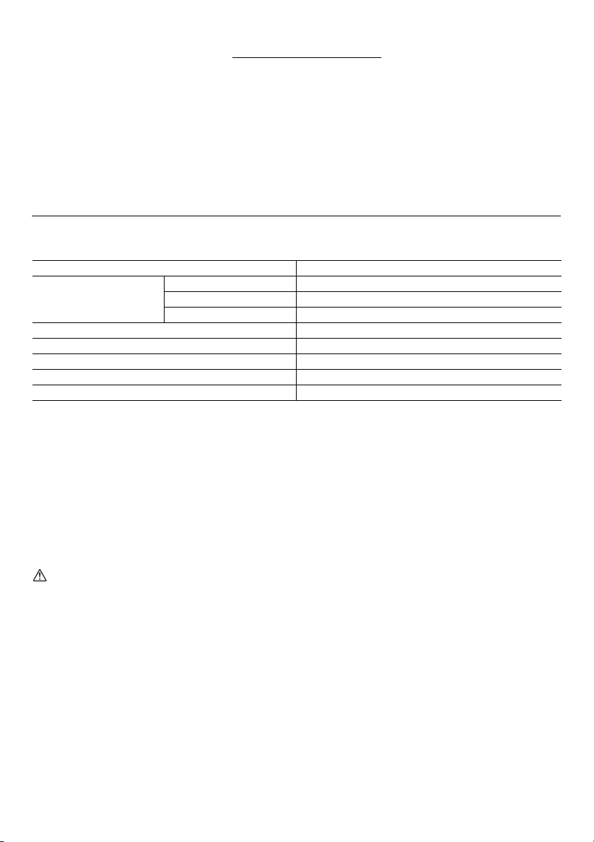
SPECIFICATIONS
Model DHR202
Concrete 20 mm
Capacities
No load speed (min
Blows per minute 0 - 4,000
Overall length 358 mm
Net weight 3.5 kg
Rated voltage D.C. 18 V
• Due to our continuing program of research and development, the specifications herein are subject to change without
notice.
• Specifications and battery cartridge may differ from country to country.
• Weight, with battery cartridge, according to EPTA-Procedure 01/2003
Intended use
The tool is intended for hammer drilling and drilling in
brick, concrete and stone as well as for chiselling work.
It is also suitable for drilling without impact in wood, metal,
ceramic and plastic.
General Power Tool Safety
Warnings
WARNING Read all safety warnings and all
instructions. Failure to follow the warnings and
instructions may result in electric shock, fire and/or
serious injury.
Save all warnings and
instructions for future reference.
CORDLESS ROTARY HAMMER
SAFETY WARNINGS
1. Wear ear protectors. Exposure to noise can cause
hearing loss.
2. Use auxiliary handle(s), if supplied with the tool.
Loss of control can cause personal injury.
3. Hold power tool by insulated gripping surfaces,
when performing an operation where the cutting
accessory may contact hidden wiring. Cutting
Steel 13 mm
Wood 26 mm
-1
) 0 - 1,200
ENE043-1
GEA010-1
GEB046-2
accessory contacting a “live” wire may make exposed
metal parts of the power tool “live” and could give the
operator an electric shock.
4. Wear a hard hat (safety helmet), safety glasses
and/or face shield. Ordinary eye or sun glasses
are NOT safety glasses. It is also highly
recommended that you wear a dust mask and
thickly padded gloves.
5. Be sure the bit is secured in place before
operation.
6. Under normal operation, the tool is designed to
produce vibration. The screws can come loose
easily, causing a breakdown or accident. Check
tightness of screws carefully before operation.
7. In cold weather or when the tool has not been
used for a long time, let the tool warm up for a
while by operating it under no load. This will
loosen up the lubrication. Without proper warmup, hammering operation is difficult.
8. Always be sure you have a firm footing.
Be sure no one is below when using the tool in
high locations.
9. Hold the tool firmly with both hands.
10. Keep hands away from moving parts.
11. Do not leave the tool running. Operate the tool
only when hand-held.
12. Do not point the tool at any one in the area when
operating. The bit could fly out and injure
someone seriously.
5
Page 6

13. Do not touch the bit or parts close to the bit
immediately after operation; they may be
extremely hot and could burn your skin.
14. Some material contains chemicals which may be
toxic. Take caution to prevent dust inhalation and
skin contact. Follow material supplier safety data.
3. Charge the battery cartridge with room
temperature at 10°C - 40°C (50°F - 104°F). Let a hot
battery cartridge cool down before charging it.
4. Charge the battery cartridge once in every six
months if you do not use it for a long period of
time.
SAVE THESE INSTRUCTIONS.
WARNING:
DO NOT let comfort or familiarity with product (gained
from repeated use) replace strict adherence to safety
rules for the subject product. MISUSE or failure to
follow the safety rules stated in this instruction
manual may cause serious personal injury.
IMPORTANT SAFETY
INSTRUCTIONS ENC007-7
FOR BATTERY CARTRIDGE
1. Before using battery cartridge, read all
instructions and cautionary markings on (1)
battery charger, (2) battery, and (3) product using
battery.
2. Do not disassemble battery cartridge.
3. If operating time has become excessively shorter,
stop operating immediately. It may result in a risk
of overheating, possible burns and even an
explosion.
4. If electrolyte gets into your eyes, rinse them out
with clear water and seek medical attention right
away. It may result in loss of your eyesight.
5. Do not short the battery cartridge:
(1) Do not touch the terminals with any
conductive material.
(2) Avoid storing battery cartridge in a container
with other metal objects such as nails, coins,
etc.
(3) Do not expose battery cartridge to water or
rain.
A battery short can cause a large current flow,
overheating, possible burns and even a
breakdown.
6. Do not store the tool and battery cartridge in
locations where the temperature may reach or
exceed 50°C (122°F).
7. Do not incinerate the battery cartridge even if it is
severely damaged or is completely worn out. The
battery cartridge can explode in a fire.
8. Be careful not to drop or strike battery.
9. Do not use a damaged battery.
SAVE THESE INSTRUCTIONS.
Tips for maintaining maximum battery life
1. Charge the battery cartridge before completely
discharged.
Always stop tool operation and charge the battery
cartridge when you notice less tool power.
2. Never recharge a fully charged battery cartridge.
Overcharging shortens the battery service life.
FUNCTIONAL DESCRIPTION
CAUTION:
• Always be sure that the tool is switched off and the
battery cartridge is removed before adjusting or
checking function on the tool.
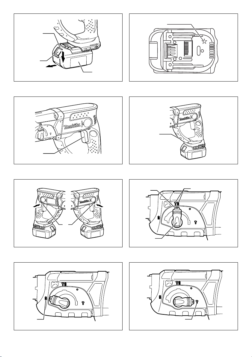
Installing or removing battery cartridge
(Fig. 1)
• Always switch off the tool before installing or removing
of the battery cartridge.
• To remove the battery cartridge, slide it from the tool
while sliding the button on the front of the cartridge.
• To install the battery cartridge, align the tongue on the
battery cartridge with the groove in the housing and slip
it into place. Always insert it all the way until it locks in
place with a little click. If you can see the red indicator
on the upper side of the button, it is not locked
completely. Install it fully until the red indicator cannot
be seen. If not, it may accidentally fall out of the tool,
causing injury to you or someone around you.
• Do not use force when installing the battery cartridge. If
the cartridge does not slide in easily, it is not being
inserted correctly.
Battery protection system (Lithium-ion
battery with star marking) (Fig. 2)
Lithium-ion batteries with a star marking are equipped
with a protection system. This system automatically cuts
off power to the tool to extend battery life.
The tool will automatically stop during operation if the tool
and/or battery are placed under one of the following
conditions:
• Overloaded:
The tool is operated in a manner that causes it to
draw an abnormally high current.
In this situation, release the trigger switch on the tool
and stop the application that caused the tool to
become overloaded. Then pull the trigger switch
again to restart.
If the tool does not start, the battery is overheated. In
this situation, let the battery cool before pulling the
trigger switch again.
• Low battery voltage:
The remaining battery capacity is too low and the tool
will not operate. In this situation, remove and
recharge the battery.
Switch action (Fig. 3)
CAUTION:
• Before inserting the battery cartridge into the tool,
always check to see that the switch trigger actuates
properly and returns to the “OFF” position when
released.
6
Page 7

To start the tool, simply pull the switch trigger. Tool speed
is increased by increasing pressure on the switch trigger.
Release the switch trigger to stop.
Lighting up the lamp (Fig. 4)
CAUTION:
• Do not look in the light or see the source of light
directly.
Pull the switch trigger to light up the lamp. The lamp
keeps on lighting while the switch trigger is being pulled.
The light automatically goes out 10 - 15 seconds after the
switch trigger is released.
NOTE:
• Use a dry cloth to wipe the dirt off the lens of lamp. Be
careful not to scratch the lens of lamp, or it may lower
the illumination.
• Do not use thinner or gasoline to clean the lamp. Such
solvents may damage it.
Reversing switch action (Fig. 5)
This tool has a reversing switch to change the direction of
rotation. Depress the reversing switch lever from the A
side for clockwise rotation or from the B side for
counterclockwise rotation.
When the reversing switch lever is in the neutral position,
the switch trigger cannot be pulled.
CAUTION:
• Always check the direction of rotation before operation.
• Use the reversing switch only after the tool comes to a
complete stop. Changing the direction of rotation
before the tool stops may damage the tool.
• When not operating the tool, always set the reversing
switch lever to the neutral position.
Selecting the action mode
Rotation with hammering (Fig. 6)
For drilling in concrete, masonry, etc., depress the lock
button and rotate the action mode changing knob to the
symbol. Use a tungsten-carbide tipped bit.
Rotation only (Fig. 7)
For drilling in wood, metal or plastic materials, depress the
lock button and rotate the action mode changing knob to
the symbol. Use a twist drill bit or wood bit.
Hammering only (Fig. 8)
For chipping, scaling or demolition operations, depress
the lock button and rotate the action mode changing knob
to the symbol. Use a bull point, cold chisel, scaling
chisel, etc.
CAUTION:
• Do not rotate the action mode changing knob when the
tool is running. The tool will be damaged.
• To avoid rapid wear on the mode change mechanism,
be sure that the action mode changing knob is always
positively located in one of the three action mode
positions.
Torque limiter
The torque limiter will actuate when a certain torque level
is reached. The motor will disengage from the output
shaft. When this happens, the bit will stop turning.
CAUTION:
• As soon as the torque limiter actuates, switch off the
tool immediately. This will help prevent premature wear
of the tool.
• Hole saws cannot be used with this tool. They tend to
pinch or catch easily in the hole. This will cause the
torque limiter to actuate too frequently.
ASSEMBLY
CAUTION:
• Always be sure that the tool is switched off and the
battery cartridge is removed before carrying out any
work on the tool.
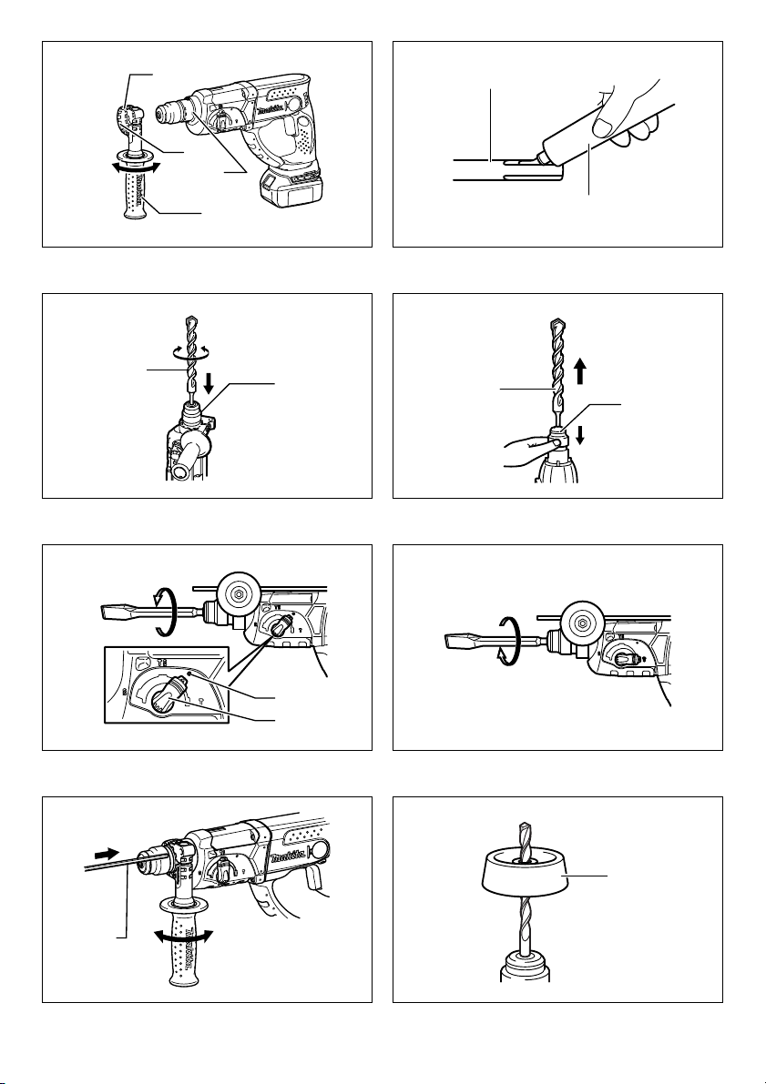
Side grip (auxiliary handle) (Fig. 9)
CAUTION:
• Always use the side grip to ensure operating safety.
Install the side grip so that the teeth on the grip fit in
between the protrusions on the tool barrel. Then tighten
the grip by turning clockwise at the desired position. It
may be swung 360° so as to be secured at any position.
Bit grease
Coat the bit shank head beforehand with a small amount
of bit grease (about 0.5 -1 g). This chuck lubrication
assures smooth action and longer service life.
Installing or removing the bit
Clean the bit shank and apply bit grease before installing
the bit. (Fig. 10)
Insert the bit into the tool. Turn the bit and push it in until it
engages. (Fig. 11)
If the bit cannot be pushed in, remove the bit. Pull the
chuck cover down a couple of times. Then insert the bit
again. Turn the bit and push it in until it engages.
After installing, always make sure that the bit is securely
held in place by trying to pull it out.
To remove the bit, pull the chuck cover down all the way
and pull the bit out. (Fig. 12)
Bit angle (when chipping, scaling or
demolishing) (Fig. 13)
The bit can be secured at the desired angle. To change
the bit angle, depress the lock button and rotate the action
mode changing knob to the
desired angle.
Depress the lock button and rotate the action mode
changing knob to the symbol. Then make sure that the
bit is securely held in place by turning it slightly. (Fig. 14)
Depth gauge (Fig. 15)
The depth gauge is convenient for drilling holes of uniform
depth. Loosen the side grip and insert the depth gauge
into the hole in the side grip. Adjust the depth gauge to the
desired depth and tighten the side grip.
NOTE:
• The depth gauge cannot be used at the position where
the depth gauge strikes against the gear housing.
Dust cup (Fig. 16)
Use the dust cup to prevent dust from falling over the tool
and on yourself when performing overhead drilling
O
symbol. Turn the bit to the
7
Page 8

operations. Attach the dust cup to the bit as shown in the
figure. The size of bits which the dust cup can be attached
to is as follows.
Bit diameter
Dust cup 5 6 mm - 14.5 mm
Dust cup 9 12 mm - 16 mm
006382
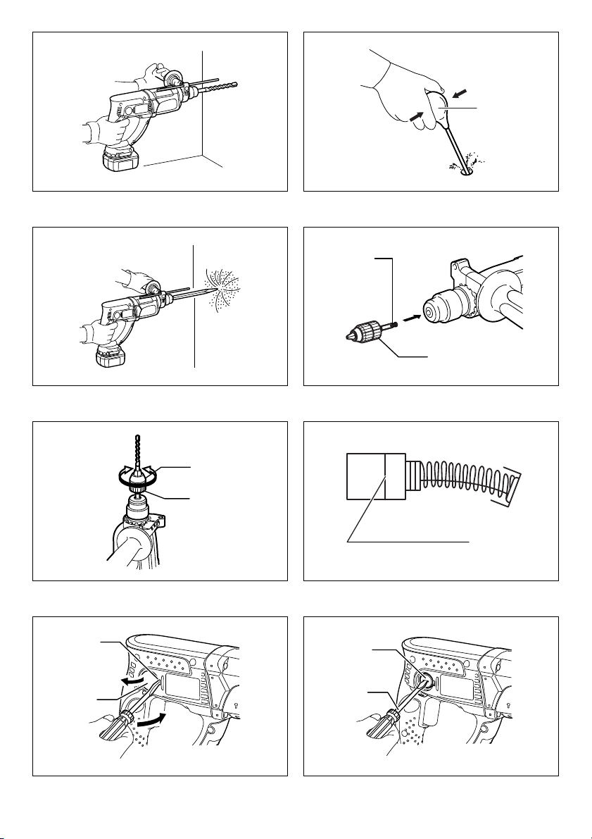
OPERATION
Hammer drilling operation (Fig. 17)
Set the action mode changing knob to the symbol.
Position the bit at the desired location for the hole, then
pull the switch trigger.
Do not force the tool. Light pressure gives best results.
Keep the tool in position and prevent it from slipping away
from the hole.
Do not apply more pressure when the hole becomes
clogged with chips or particles. Instead, run the tool at an
idle, then remove the bit partially from the hole. By
repeating this several times, the hole will be cleaned out
and normal drilling may be resumed.
CAUTION:
• There is a tremendous and sudden twisting force
exerted on the tool/bit at the time of hole breakthrough, when the hole becomes clogged with chips
and particles, or when striking reinforcing rods
embedded in the concrete. Always use the side grip
(auxiliary handle) and firmly hold the tool by both side
grip and switch handle during operations. Failure to do
so may result in the loss of control of the tool and
potentially severe injury.
NOTE:
Eccentricity in the bit rotation may occur while operating
the tool with no load. The tool automatically centers itself
during operation. This does not affect the drilling
precision.
Blow-out bulb (optional accessory)
(Fig. 18)
After drilling the hole, use the blow-out bulb to clean the
dust out of the hole.
Chipping/Scaling/Demolition (Fig. 19)
Set the action mode changing knob to the symbol.
Hold the tool firmly with both hands. Turn the tool on and
apply slight pressure on the tool so that the tool will not
bounce around, uncontrolled. Pressing very hard on the
tool will not increase the efficiency.
Drilling in wood or metal (Fig. 20 & 21)
Use the optional drill chuck assembly. When installing it,
refer to “Installing or removing the bit” described on the
previous page.
Set the action mode changing knob so that the pointer
points to the symbol.
CAUTION:
• Never use “rotation with hammering” when the drill
chuck assembly is installed on the tool. The drill chuck
assembly may be damaged. Also, the drill chuck will
come off when reversing the tool.
8
• Pressing excessively on the tool will not speed up the
drilling. In fact, this excessive pressure will only serve
to damage the tip of your bit, decrease the tool
performance and shorten the service life of the tool.
• There is a tremendous twisting force exerted on the
tool/bit at the time of hole breakthrough. Hold the tool
firmly and exert care when the bit begins to break
through the workpiece.
• A stuck bit can be removed simply by setting the
reversing switch to reverse rotation in order to back
out. However, the tool may back out abruptly if you do
not hold it firmly.
• Always secure small workpieces in a vise or similar
hold-down device.
MAINTENANCE
CAUTION:
• Always be sure that the tool is switched off and the
battery cartridge is removed before attempting to
perform inspection or maintenance.
• Never use gasoline, benzine, thinner, alcohol or the
like. Discoloration, deformation or cracks may result.
Replacing carbon brushes (Fig. 22)
Remove and check the carbon brushes regularly.
Replace when they wear down to the limit mark. Keep the
carbon brushes clean and free to slip in the holders.
Both carbon brushes should be replaced at the same
time. Use only identical carbon brushes.
Remove holder cap covers by inserting the slotted bit
screwdriver into the recessed part in the tool and lifting it
up. (Fig. 23)
Use a screwdriver to remove the brush holder caps.
Take out the worn carbon brushes, insert the new ones
and secure the brush holder caps. (Fig. 24)
Remount the holder cap covers on the tool.
To maintain product SAFETY and RELIABILITY, repairs,
any other maintenance or adjustment should be
performed by Makita Authorized Service Centers, always
using Makita replacement parts.
OPTIONAL ACCESSORIES
CAUTION:
• These accessories or attachments are recommended
for use with your Makita tool specified in this manual.
The use of any other accessories or attachments might
present a risk of injury to persons. Only use accessory
or attachment for its stated purpose.
If you need any assistance for more details regarding
these accessories, ask your local Makita Service Center.
• SDS-Plus Carbide-tipped bits
• Bull point
• Cold chisel
• Scaling chisel
• Grooving chisel
• Drill chuck assembly
• Drill chuck S13
• Chuck adapter
• Chuck key S13
• Bit grease
• Side grip
• Depth gauge
Page 9

• Blow-out bulb
•Dust cup
• Dust extractor attachment
• Safety goggles
• Plastic carrying case
• Keyless drill chuck
• Various type of Makita genuine batteries and chargers
NOTE:
• Some items in the list may be included in the tool
package as standard accessories. They may differ
from country to country.
The Technical file in accordance with 2006/42/EC is
available from:
Makita, Jan-Baptist Vinkstraat 2, 3070, Belgium
31. 12. 2013
Yasushi Fukaya
Director
Makita, Jan-Baptist Vinkstraat 2, 3070, Belgium
Noise
ENG905-1
The typical A-weighted noise level determined according
to EN60745:
Sound pressure level (L
Sound power level (L
Uncertainty (K): 3 dB (A)
): 87 dB (A)
pA
): 98 dB (A)
WA
Wear ear protection.
Vibration
ENG900-1
The vibration total value (tri-axial vector sum) determined
according to EN60745:
Work mode: hammer drilling into concrete
Vibration emission (a
Uncertainty (K): 1.5 m/s
): 14.5 m/s
h,HD
2
Work mode: chiselling
Vibration emission (a
Uncertainty (K): 1.5 m/s
h,CHeq
2
Work mode: drilling into metal
Vibration emission (a
Uncertainty (K): 1.5 m/s
): 3.0 m/s
h,D
2
): 11.0 m/s
2
2
2
ENG901-1
• The declared vibration emission value has been
measured in accordance with the standard test method
and may be used for comparing one tool with another.
• The declared vibration emission value may also be
used in a preliminary assessment of exposure.
WARNING:
• The vibration emission during actual use of the power
tool can differ from the declared emission value
depending on the ways in which the tool is used.
• Be sure to identify safety measures to protect the
operator that are based on an estimation of exposure in
the actual conditions of use (taking account of all parts
of the operating cycle such as the times when the tool
is switched off and when it is running idle in addition to
the trigger time).
For European countries only
ENH101-17
EC Declaration of Conformity
Makita declares that the following Machine(s):
Designation of Machine:
Cordless Combination Hammer
Model No./Type: DHR202
Conforms to the following European Directives:
2006/42/EC
They are manufactured in accordance with the following
Standard or standardized documents:
EN60745
9
Page 10

NEDERLANDS (Originele instructies)
Verklaring van algemene gegevens
1. Rode deel
2. Knop
3. Accu
4. Ster-merkteken
5. Aan/uit-schakelaar
6. Lamp
7. Omkeerschakelaarknop
8. Roteren met hameren
9. Vastzetknop
10. Omschakelknop
11. Alleen roteren
12. Alleen hameren
13. Basis van de zijhandgreep
14. Tanden
15. Zijhandgreep
16. Uitsteeksel
17. Losdraaien
18. Vastzetten
19. Boorschacht
20. Boorvet
21. Boor
22. Boorkopdeksel
23. O-symbool
24. Diepteaanslag
25. Stofvanger
26. Blaasbalgje
27. Boorkop-adapter
28. Sleutelloze boorkop
29. Bus
30. Ring
31. Slijtgrensmarkering
32. Verdiepte deel
33. Houderafdekking
34. Koolborsteldop
35. Schroevendraaier
TECHNISCHE GEGEVENS
Model DHR202
Beton 20 mm
Vermogen
Nullasttoerental (min
Aantal slagen/minuut 0 - 4.000
Totale lengte 358 mm
Netto gewicht 3,5 kg
Nominale spanning 18 V gelijkstroom
• Als gevolg van ons doorlopende onderzoeks- en ontwikkelingsprogramma, zijn de technische gegevens van dit
gereedschap onderhevig aan veranderingen zonder voorafgaande kennisgeving.
• Specificaties en accu’s kunnen van land tot land verschillen.
• Gewicht, inclusief de accu, volgens de EPTA-procedure 01/2003
Gebruiksdoeleinden
Het gereedschap is bedoeld voor hamerboren en boren in
baksteen, beton en steen, en tevens voor beitelwerk.
Het is ook geschikt voor boren zonder slag in hout,
metaal, keramisch materiaal en kunststof.
Algemene
veiligheidswaarschuwingen voor
elektrisch gereedschap GEA010-1
WAARSCHUWING Lees alle
veiligheidswaarschuwingen en alle instructies. Het
niet volgen van de waarschuwingen en instructies kan
leiden tot elektrische schokken, brand en/of ernstig letsel.
Bewaar alle waarschuwingen en
instructies om in de toekomst te
kunnen raadplegen.
VEILIGHEIDSWAARSCHUWINGEN
SPECIFIEK VOOR EEN
ACCUBOORHAMER
1. Draag gehoorbescherming. Blootstelling aan harde
geluiden kan leiden tot gehoorbeschadiging.
2. Gebruik de hulphandgrepen, als deze bij het
gereedschap werden geleverd. Als u de controle
28
Staal 13 mm
Hout 26 mm
-1
) 0 - 1.200
ENE043-1
GEB046-2
over het gereedschap verliest, kan dit leiden tot
persoonlijk letsel.
3. Houd het elektrisch gereedschap vast aan het
geïsoleerde oppervlak van de handgrepen
wanneer u werkt op plaatsen waar het
booraccessoire met verborgen bedrading in
aanraking kan komen. Wanneer het bitaccessoire in
aanraking komen met onder spanning staande
draden, zullen de niet-geïsoleerde metalen delen van
het gereedschap onder spanning komen te staan
zodat de gebruiker een elektrische schok kan krijgen.
4. Draag een veiligheidshelm, veiligheidsbril en/of
spatscherm. Een gewone bril of een zonnebril is
GEEN veiligheidsbril. Het wordt tevens sterk
aanbevolen een stofmasker en dik gevoerde
handschoenen te dragen.
5. Controleer of het bit stevig op zijn plaats zit
voordat u het gereedschap gebruikt.
6. Bij normale bediening behoort het gereedschap te
trillen. De schroeven kunnen gemakkelijk
losraken, waardoor een defect of ongeluk kan
ontstaan. Controleer of de schroeven goed zijn
aangedraaid, alvorens het gereedschap te
gebruiken.
7. In koude weersomstandigheden of wanneer het
gereedschap gedurende een lange tijd niet is
gebruikt, laat u het gereedschap eerst opwarmen
door het onbelast te laten werken. Hierdoor zal de
Page 11

smering worden verbeterd. Zonder degelijk
opwarmen, zal de hamerwerking moeilijk zijn.
8. Zorg er altijd voor dat u stevig staat.
Zorg ervoor dat er niemand zich onder u bevindt
wanneer u het gereedschap op een hoge plaats
gebruikt.
9. Houd het gereedschap met beide handen stevig
vast.
10. Houd uw handen uit de buurt van bewegende
delen.
11. Laat het gereedschap niet ingeschakeld liggen.
Bedien het gereedschap alleen wanneer u het
vasthoudt.
12. Richt het gereedschap niet op iemand in de buurt
terwijl het is ingeschakeld. Het bit zou eruit
kunnen vliegen en iemand ernstig verwonden.
13. Raak het bit en onderdelen in de buurt van het bit
niet onmiddellijk na gebruik aan. Zij kunnen
bijzonder heet zijn en brandwonden op uw huid
veroorzaken.
14. Sommige materialen bevatten chemische stoffen
die giftig kunnen zijn. Neem
voorzorgsmaatregelen tegen het inademen van
stof en contact met de huid. Volg de
veiligheidsinstructies van de leverancier van het
materiaal op.
BEWAAR DEZE INSTRUCTIES.
WAARSCHUWING:
Laat u NIET misleiden door een vals gevoel van
comfort en bekendheid met het gereedschap (na
veelvuldig gebruik) en neem alle
veiligheidsvoorschriften van het betreffende product
altijd strikt in acht. VERKEERD GEBRUIK of het niet
volgen van de veiligheidsinstructies in deze
gebruiksaanwijzing kan leiden tot ernstig persoonlijk
letsel.
BELANGRIJKE
VEILIGHEIDSINSTRUCTIES
ENC007-7
VOOR ACCU’S
1. Alvorens de accu in gebruik te nemen, leest u
eerst alle instructies en
waarschuwingsopschriften op (1) de acculader, (2)
de accu en (3) het apparaat waarin de accu wordt
aangebracht.
2. Haal de accu niet uit elkaar.
3. Als de gebruikstijd aanzienlijk korter is geworden,
stopt u onmiddellijk met het gebruik. Anders kan
dit leiden tot kans op oververhitting, mogelijke
brandwonden en zelfs een explosie.
4. Als de elektrolyt in uw ogen komt, wast u deze uit
met schoon water en raadpleegt u onmiddellijk
een arts. Dit kan leiden tot verlies van
gezichtsvermogen.
5. Sluit de accu niet kort:
(1) Raak de accupolen niet aan met enig
geleidend materiaal.
(2) Bewaar de accu niet op een plaats waar deze
in aanraking kan komen met andere metalen
voorwerpen, zoals spijkers, munten, enz.
(3) Stel de accu niet bloot aan water of regen.
Kortsluiting van de accu kan leiden tot een hoge
stroomsterkte, oververhitting, mogelijke
brandwonden en zelfs een defect.
6. Bewaar het gereedschap en de accu niet op
plaatsen waar de temperatuur kan oplopen tot
50 °C of hoger.
7. Werp de accu niet in een vuur, zelfs niet als deze
al ernstig beschadigd of helemaal versleten is. De
accu kan in een vuur exploderen.
8. Wees voorzichtig dat u de accu niet laat vallen of
ergens tegenaan stoot.
9. Gebruik nooit een beschadigde accu.
BEWAAR DEZE INSTRUCTIES.
Tips voor een lange levensduur van de
accu
1. Laad de accu op voordat deze volledig leeg is.
Wanneer u merkt dat het gereedschap minder
vermogen heeft, stopt u met het gebruik ervan en
laadt u eerst de accu op.
2. Laad nooit een volledig opgeladen accu op.
Te lang opladen verkort de levensduur van de
accu.
3. Laad de accu op bij een omgevingstemperatuur
van 10 °C tot 40 °C. Laat een warme accu eerst
afkoelen voordat u deze oplaadt.
4. Laad de accu ieder half jaar op als u deze
gedurende een lange tijd niet gebruikt.
BESCHRIJVING VAN DE
FUNCTIES
LET OP:
• Controleer altijd of het gereedschap is uitgeschakeld
en de accu is verwijderd alvorens de functies van het
gereedschap te controleren of af te stellen.
De accu aanbrengen en verwijderen (zie
afb. 1)
• Schakel het gereedschap altijd uit voordat u de accu
aanbrengt of verwijdert.
• Om de accu te verwijderen verschuift u de knop aan de
voorkant van de accu en schuift u tegelijkertijd de accu
van het gereedschap af.
• Om de accu aan te brengen lijnt u de lip op de accu uit
met de groef in de behuizing en duwt u de accu op zijn
plaats. Steek de accu zo ver mogelijk in het
gereedschap tot u een klikgeluid hoort. Als u het rode
deel aan de bovenkant van de knop kunt zien, is de
accuadapter niet goed aangebracht. Breng de
accuadapter zo ver mogelijk aan tot het rode deel niet
meer zichtbaar is. Als u dit niet doet, kan de accu per
ongeluk uit het gereedschap vallen en u of anderen in
uw omgeving verwonden.
• Oefen geen grote kracht uit bij het aanbrengen van de
accu. Als de accu niet gemakkelijk erin kan worden
geschoven, wordt deze niet goed aangebracht.
29
Page 12

Accubeveiligingssysteem (lithiumionaccu
met een ster-merkteken) (zie afb. 2)
Lithiumionaccu’s met een ster-merkteken zijn uitgerust
met een beveiligingssysteem. Dit systeem schakelt
automatisch de voeding naar het gereedschap uit om de
levensduur van de accu te verlengen.
Het gereedschap zal tijdens gebruik automatisch stoppen
wanneer het gereedschap en/of de accu zich in een van
de volgende omstandigheden bevinden:
• Overbelasting:
Het gereedschap wordt gebruikt op een manier die
ertoe leidt dat een abnormaal hoge stroomsterkte uit
de accu wordt getrokken.
Laat in die situatie de aan/uit-schakelaar van het
gereedschap los en stop het gebruik dat ertoe leidde
dat het gereedschap overbelast werd. Knijp daarna
opnieuw de aan/uit-schakelaar in om het
gereedschap weer in te schakelen.
Als het gereedschap niet wordt ingeschakeld, is de
accu oververhit. In die situatie laat u de accu eerst
afkoelen voordat u opnieuw de aan/uit-schakelaar
inknijpt.
• Lage accuspanning:
De resterende acculading is te laag en het
gereedschap wordt niet ingeschakeld. Verwijder in
die situatie de accu en laad hem op.
In- en uitschakelen (zie afb. 3)
LET OP:
• Controleer altijd, voordat u de accu in het gereedschap
steekt, of de aan/uit-schakelaar op de juiste manier
schakelt en weer terugkeert naar de uit-stand nadat
deze is losgelaten.
Om het gereedschap in te schakelen, knijpt u gewoon de
aan/uit-schakelaar in. De draaisnelheid van het
gereedschap neemt toe naarmate u meer druk uitoefent
op de aan/uit-schakelaar. Laat de aan/uit-schakelaar los
om het gereedschap te stoppen
De lamp inschakelen (zie afb. 4)
LET OP:
• Kijk niet rechtstreeks in het licht of naar de bron van de
lamp.
Knijp de aan/uit-schakelaar in om de lamp op de voorkant
in te schakelen. De lamp blijft branden zolang u de aan/
uit-schakelaar ingeknepen houdt.
De lamp gaat 10 tot 15 seconden nadat de aan/uitschakelaar is losgelaten automatisch uit.
OPMERKING:
• Gebruik een doek om het vuil van de lens van de lamp
te vegen. Wees voorzichtig dat u de lens van de lamp
niet bekrast om de lichtopbrengst niet te verlagen.
• Maak de lens van de lamp niet schoon met verdunner
of benzine. Dergelijke oplosmiddelen kunnen de lens
van de lamp beschadigen.
Werking van de omkeerschakelaar (zie
afb. 5)
Dit gereedschap is uitgerust met een omkeerschakelaar
waarmee u de draairichting kunt omkeren. Druk op de
omkeerschakelaar vanaf kant A voor de draairichting
rechtsom, of vanaf kant B voor de draairichting linksom.
30
Wanneer de omkeerschakelaar in de middenstand staat,
kunt u de aan/uit-schakelaar niet inknijpen.
LET OP:
• Controleer altijd de draairichting alvorens het
gereedschap te gebruiken.
• Gebruik de omkeerschakelaar alleen nadat het
gereedschap volledig tot stilstand is gekomen. Als u de
draairichting verandert voordat het gereedschap
volledig stilstaat, kan het gereedschap worden
beschadigd.
• Als u het gereedschap niet gebruikt, zet u de
omkeerschakelaar altijd in de middenstand.
De werkingsfunctie selecteren
Roteren met hameren (zie afb. 6)
Voor het boren in beton, metselwerk, enz., drukt u de
vastzetknop in en draait u de omschakelknop naar het
symbool. Gebruik een boor met een hardmetalen punt.
Alleen roteren (zie afb. 7)
Voor het boren in hout, metaal of kunststofmaterialen,
drukt u de vastzetknop in en draait u de omschakelknop
naar het symbool. Gebruik een spiraalboor of houtboor.
Alleen hameren (zie afb. 8)
Voor het beitelen, bikken of sloopwerkzaamheden, drukt u
de vastzetknop in en draait u de omschakelknop naar het
symbool. Gebruik een rond boor, koudbeitel, bikbeitel,
enz.
LET OP:
• Draai de omschakelknop niet terwijl het gereedschap
draait. Het gereedschap zal hierdoor worden
beschadigd.
• Om snelle slijtage van het omschakelmechanisme te
voorkomen, zorgt u ervoor dat de omschakelknop altijd
precies in een van de drie standen staat.
Koppelbegrenzer
De koppelbegrenzer treedt in werking wanneer de motor
een bepaald koppel bereikt. De motor wordt dan
ontkoppeld van de uitgangsas. Wanneer dit gebeurt, zal
de boor ophouden met draaien.
LET OP:
• Schakel het gereedschap onmiddellijk uit wanneer de
koppelbegrenzer in werking treedt. Hiermee helpt u
vroegtijdige slijtage van het gereedschap voorkomen.
• Gatenzagen kunnen met dit gereedschap niet worden
gebruikt. Deze lopen of klemmen gemakkelijk vast in
het boorgat. De koppelbegrenzer treedt hierdoor te
vaak in werking.
ONDERDELEN AANBRENGEN/
VERWIJDEREN
LET OP:
• Controleer altijd of het gereedschap is uitgeschakeld
en de accu is verwijderd alvorens enige
werkzaamheden aan het gereedschap te verrichten.
Zijhandgreep (hulphandgreep) (zie afb. 9)
LET OP:
• Gebruik altijd de zijhandgreep om veilig te kunnen
werken.
Page 13

Plaats de zijhandgreep zodanig over de kop van het
gereedschap dat de tanden van de zijhandgreep in de
uitsteeksels van het gereedschap passen. Draai daarna
de zijhandgreep vast door deze in de gewenste stand
rechtsom te draaien. De zijhandgreep kan 360° rond het
gereedschap gedraaid worden en in iedere gewenste
stand worden vastgezet.
Boorvet
Voordat u de boor aanbrengt, smeert u een beetje vet (ca.
0,5 tot 1,00 gram) op de kop van de boorschacht. Met een
ingevette boorkop zal het gereedschap beter werken en
langer meegaan.
Aanbrengen en verwijderen van de boor
Reinig de boorschacht en smeer er boorvet op alvorens
de boor te installeren. (zie afb. 10)
Steek de boor in het gereedschap. Draai de boor en duw
deze naar binnen tot zij vergrendelt. (zie afb. 11)
Als de boor niet naar binnen kan worden geduwd, haalt u
de boor eruit. Trek het boorkopdeksel enkel keren
omlaag. Steek de boor daarna opnieuw naar binnen.
Draai de boor en duw deze naar binnen tot zij vergrendelt.
Controleer na het aanbrengen altijd of het bit stevig in het
gereedschap is bevestigd door te proberen het eruit te
trekken.
Om de bit te verwijderen, trekt u de verwisselring
helemaal omlaag en vervolgens de bit eruit. (zie afb. 12)
Beitelhoek (bij beitelen, bikken of slopen)
(zie afb. 13)
De beitel kan onder de gewenste hoek worden vastgezet.
Om de beitelhoek te veranderen, drukt u de vastzetknop
in en draait u de omschakelknop naar het
Draai de beitel naar de gewenste hoek.
Druk de vastzetknop in en draai de omschakelknop naar
het symbool. Controleer daarna of de bit stevig op zijn
plaats vastzit door deze iets te verdraaien. (zie afb. 14)
O
symbool.
Diepteaanslag (zie afb. 15)
De diepteaanslag is handig voor het boren van gaten van
gelijke diepte. Maak de zijhandgreep los en steek de
diepteaanslag in het gat in de zijhandgreep. Stel de
diepteaanslag af op de gewenste diepte en zet de
zijhandgreep vast.
OPMERKING:
• De diepteaanslag kan niet worden gebruikt in de
positie waarbij deze tegen het tandwielhuis aanstoot.
Stofvanger (zie afb. 16)
Gebruik de stofvanger om te voorkomen dat stof op het
gereedschap en op uzelf terechtkomt wanneer u boven
uw hoofd boort. Bevestig de stofvanger aan de boor zoals
aangegeven in de afbeelding. De diameter van de boren
waaraan de stofvanger kan worden bevestigd is als volgt.
Stofvanger 5 6 mm t/m 14,5 mm
Stofvanger 9 12 mm t/m 16 mm
006382
Boordiameter
BEDIENING
Gebruik als hamerboor (zie afb. 17)
Draai de omschakelknop naar het symbool.
Plaats de punt van de boor op de gewenste plaats waar
geboord moet worden en trek vervolgens de schakelaar
in.
Forceer het gereedschap niet. Een lichte druk geeft de
beste resultaten.
Houd het gereedschap stevig vast en zorg dat het niet
uitglijdt.
Oefen geen grotere druk uit wanneer het boorgat verstopt
raakt met schilfertjes of metaaldeeltjes. Laat in zo’n geval
het gereedschap langzaam lopen en verwijder de boor
gedeeltelijk uit het boorgat. Wanneer dit verschillende
keren wordt herhaald, zal het boorgat schoon worden en
kunt u normaal verder boren.
LET OP:
• Op het moment dat het boorgat doorbreekt, het
boorgat verstopt raakt met schilfertjes of
metaaldeeltjes, of de boorhamer de bewapening in het
beton raakt, wordt een enorme kracht uitgeoefend op
het gereedschap/de boor. Gebruik altijd de
zijhandgreep (hulphandgreep) en houd het
gereedschap tijdens gebruik stevig vast aan zowel de
zijhandgreep als de hoofdhandgreep Als u dit niet doet,
kan u de controle over het gereedschap verliezen en
mogelijk ernstig letsel veroorzaken.
OPMERKING:
Terwijl het gereedschap onbelast wordt gebruikt, kan de
boor excentrisch draaien. Het gereedschap centreert
zichzelf automatisch tijdens het gebruik. Dit heeft geen
nadelige invloed op de nauwkeurigheid van het boren.
Luchtblazer (los verkrijgbaar) (zie afb. 18)
Gebruik na het boren het blaasbalgje om het stof uit het
boorgat te blazen.
Beitelen, bikken en slopen (zie afb. 19)
Draai de omschakelknop naar het symbool.
Houd het gereedschap met beide handen stevig vast.
Schakel het gereedschap in en oefen er enige kracht op
uit zodat het gereedschap niet oncontroleerbaar in het
rond springt. Het gereedschap werkt niet efficiënter als u
grote druk op het gereedschap uitoefent.
Boren in hout of metaal (zie afb. 20 en 21)
Gebruik de los verkrijgbare boorkopmontage. Om deze te
installeren, zie “Aanbrengen en verwijderen van de boor”
op de vorige pagina.
Draai de omschakelknop zodanig dat de aanwijspunt naar
het symbool wijst.
LET OP:
• Gebruik nooit “Roteren met hameren” wanneer de
boorkopmontage op het gereedschap is gemonteerd.
De boorkopmontage kan hierdoor beschadigd raken.
Bovendien zal de boorkop loskomen wanneer de
draairichting van het gereedschap wordt omgekeerd.
• Het boren zal niet sneller verlopen als u hard op het
gereedschap drukt. In feite zal dergelijk duwen alleen
maar leiden tot beschadiging van de boor, verlagen
van de prestaties van het gereedschap, en verkorten
van de levensduur van het gereedschap.
31
Page 14

• Op het moment dat het boorgat doorbreekt wordt een
enorme draaikracht uitgeoefend op het gereedschap/
de boor. Houd het gereedschap stevig vast en let goed
op wanneer het bit door het werkstuk breekt.
• Een vastgelopen boor kan eenvoudigweg worden
verwijderd door de omkeerschakelknop in de stand
voor achteruitdraaien te zetten om de boor te
verwijderen. Het gereedschap kan echter plotseling
achteruit komen als u het niet stevig vasthoudt.
• Zet kleine werkstukken altijd vast in een bankschroef of
soortgelijk bevestigingsmiddel.
ONDERHOUD
LET OP:
• Zorg er altijd voor dat de machine is uitgeschakeld en
de accu is verwijderd, voordat u een inspectie of
onderhoud uitvoert.
• Gebruik nooit benzine, wasbenzine, thinner, alcohol,
enz. Dit kan leiden tot verkleuren, vervormen of
barsten.
De koolborstels vervangen (zie afb. 22)
Verwijder en controleer de koolborstels regelmatig.
Vervang deze wanneer ze tot aan de slijtgrensmarkering
zijn afgesleten. Houd de koolborstels schoon en zorg
ervoor dat ze vrij kunnen bewegen in de houders.
Beide koolborstels dienen tegelijkertijd te worden
vervangen. Gebruik alleen identieke koolborstels.
Verwijder de houderafdekking door een
platkopschroevendraaier in de inkeping in het
gereedschap te steken en deze omhoog te wippen. (zie
afb. 23)
Gebruik een schroevendraaier om de koolborsteldoppen
te verwijderen.
Haal de versleten koolborstels eruit, plaats de nieuwe
erin, en zet de koolborsteldoppen goed vast. (zie afb. 24)
Plaats de houderafdekkingen terug op het gereedschap.
Om de VEILIGHEID en BETROUWBAARHEID van het
gereedschap te handhaven, dienen alle reparaties,
onderhoud en afstellingen te worden uitgevoerd door een
erkend Makita-servicecentrum, en altijd met
gebruikmaking van originele Makitavervangingsonderdelen.
VERKRIJGBARE ACCESSOIRES
LET OP:
• Deze accessoires of hulpstukken worden aanbevolen
voor gebruik met het Makita-gereedschap dat in deze
gebruiksaanwijzing wordt beschreven. Het gebruik van
andere accessoires of hulpstukken kan gevaar voor
persoonlijk letsel opleveren. Gebruik de accessoires of
hulpstukken uitsluitend voor de aangegeven
gebruiksdoeleinden.
Mocht u meer informatie willen hebben over deze
accessoires, dan kunt u contact opnemen met uw
plaatselijke Makita-servicecentrum.
• SDS-Plus boren met een hardmetalen punt
• Ronde boor
• Koudbeitel
• Bikbeitel
• Groefbeitel
• Boorkopmontage
• Boorkop S13
• Boorkop-adapter
• Boorkopsleutel S13
• Boorvet
• Zijhandgreep
• Diepteaanslag
• Blaasbalgje
• Stofvanger
• Hulpstuk voor stofafscheiding
• Veiligheidsbril
• Kunststoffen draagdoos
• Sleutelloze boorkop
• Diverse types originele Makita-accu’s en acculaders
OPMERKING:
• Sommige items op de lijst kunnen zijn inbegrepen in de
doos van het gereedschap als standaard toebehoren.
Zij kunnen van land tot land verschillen.
Geluid
ENG905-1
De typische, A-gewogen geluidsniveaus zijn gemeten
volgens EN60745:
Geluidsdrukniveau (L
Geluidsvermogenniveau (L
Onzekerheid (K): 3 dB (A)
): 87 dB (A)
pA
WA
): 98 dB (A)
Draag gehoorbescherming.
Trillingen
ENG900-1
De totale trillingswaarde (triaxiale vectorsom) zoals
vastgesteld volgens EN60745:
Gebruikstoepassing: hamerboren in beton
Trillingsemissie (a
Onzekerheid (K): 1,5 m/s
): 14,5 m/s
h, HD
Gebruikstoepassing: beitelen
Trillingsemissie (a
Onzekerheid (K): 1,5 m/s
h, CHeq
Gebruikstoepassing: boren in metaal
Trillingsemissie (a
Onzekerheid (K): 1,5 m/s
): 3,0 m/s
h, D
2
): 11,0 m/s
2
2
2
2
2
ENG901-1
• De opgegeven trillingsemissiewaarde is gemeten
volgens de standaardtestmethode en kan worden
gebruikt om dit gereedschap te vergelijken met andere
gereedschappen.
• De opgegeven trillingsemissiewaarde kan ook worden
gebruikt voor een beoordeling vooraf van de
blootstelling.
WAARSCHUWING:
• De trillingsemissie tijdens het gebruik van het elektrisch
gereedschap in de praktijk kan verschillen van de
opgegeven trillingsemissiewaarde afhankelijk van de
manier waarop het gereedschap wordt gebruikt.
• Zorg ervoor dat veiligheidsmaatregelen worden
getroffen ter bescherming van de operator die zijn
gebaseerd op een schatting van de blootstelling onder
praktijkomstandigheden (rekening houdend met alle
fasen van de bedrijfscyclus, zoals de tijdsduur
gedurende welke het gereedschap is uitgeschakeld en
stationair draait, naast de ingeschakelde tijdsduur).
32
Page 15

Alleen voor Europese landen
ENH101-17
EU-verklaring van conformiteit
Makita verklaart dat de volgende machine(s):
Aanduiding van de machine:
Accucombinatiehamer
Modelnr./Type: DHR202
Voldoen aan de volgende Europese richtlijnen:
2006/42/EG
Deze zijn gefabriceerd in overeenstemming met de
volgende normen of genormaliseerde documenten:
EN60745
Het technische bestand volgens 2006/42/EG is
verkrijgbaar bij:
Makita, Jan-Baptist Vinkstraat 2, 3070, België
31. 12. 2013
Yasushi Fukaya
Directeur
Makita, Jan-Baptist Vinkstraat 2, 3070, België
33
 Loading...