

Makita DFR550, DFR750, DFR540 User Manual

INSTRUCTION MANUAL
MANUEL D'INSTRUCTION
MANUAL DE INSTRUCCIONES
Cordless Auto Feed Screwdriver
Visseuse Automatique sans Fil
Atornillador Autoalimentado
Inalámbrico
DFR540
DFR550
DFR750
IMPORTANT: Read Before Using.
IMPORTANT: Lire avant usage.
IMPORTANTE: Leer antes de usar.
008261
1

ENGLISH (Original instructions)
SPECIFICATIONS
Model DFR540 DFR550 DFR750
Screw strip
No load speed (RPM) 4,000 /min
Overall length
Net weight 2.0 kg (4.4 lbs) 2.1 kg (4.5 lbs) 2.3 kg (5.1 lbs) 2.1 kg (4.6 lbs) 2.4 kg (5.2 lbs)
Rated voltage D.C. 14.4 V D.C. 18 V
Standard battery cartridges
• Due to our continuing program of research and development, the specifications herein are subject to change without notice.
• Specifications and battery cartridge may differ from country to country.
• Weight, with battery cartridge, according to EPTA-Procedure 01/2003
General Power Tool Safety
Warnings
WARNING Read all safety warnings and all
instructions. Failure to follow the warnings and
instructions may result in electric shock, fire and/or
serious injury.
Save all warnings and
instructions for future reference.
The term "power tool" in the warnings refers to your
mains-operated (corded) power tool or battery-operated
(cordless) power tool.
Work area safety
1. Keep work area clean and well lit. Cluttered or
dark areas invite accidents.
2. Do not operate power tools in explosive
atmospheres, such as in the presence of
flammable liquids, gases or dust. Power tools
create sparks which may ignite the dust or fumes.
3. Keep children and bystanders away while
operating a power tool. Distractions can cause
you to lose control.
Electrical safety
4. Power tool plugs must match the outlet. Never
modify the plug in any way. Do not use any
adapter plugs with earthed (grounded) power
tools. Unmodified plugs and matching outlets will
reduce risk of electric shock.
5. Avoid body contact with earthed or grounded
surfaces such as pipes, radiators, ranges and
refrigerators. There is an increased risk of
electric shock if your body is earthed or grounded.
4 × 25 - 55
(5/32" x 1" x 2-3/16")
424 mm (16-3/4")
BL1430 /
BL1430B /
BL1460B
4 × 25 - 55 (5/32" x 1" x 2-3/16") 4 × 45 - 75 (5/32" x 1-3/4" x 2-15/16")
424 mm (16-3/4") 464 mm (18-1/4")
BL1815 /
BL1815N /
BL1820 /
BL1820B
GEA006-2
BL1830 / BL1830B /
BL1840 / BL1840B /
BL1850 / BL1850B /
BL1860B
BL1815 /
BL1815N /
BL1820 /
BL1820B
BL1830 / BL1830B /
BL1840 / BL1840B /
BL1850 / BL1850B /
6. Do not expose power tools to rain or wet
conditions. Water entering a power tool will
increase the risk of electric shock.
7. Do not abuse the cord. Never use the cord for
carrying, pulling or unplugging the power tool.
Keep cord away from heat, oil, sharp edges or
moving parts. Damaged or entangled cords
increase the risk of electric shock.
8. When operating a power tool outdoors, use an
extension cord suitable for outdoor use. Use of
a cord suitable for outdoor use reduces the risk of
electric shock.
9. If operating a power tool in a damp location is
unavoidable, use a ground fault circuit
interrupter (GFCI) protected supply. Use of an
GFCI reduces the risk of electric shock.
Personal safety
10. Stay alert, watch what you are doing and use
common sense when operating a power tool.
Do not use a power tool while you are tired or
under the influence of drugs, alcohol or
medication. A moment of inattention while
operating power tools may result in serious
personal injury.
11. Use personal protective equipment. Always
wear eye protection. Protective equipment such
as dust mask, non-skid safety shoes, hard hat, or
hearing protection used for appropriate conditions
will reduce personal injuries.
12. Prevent unintentional starting. Ensure the
switch is in the off-position before connecting
to power source and/or battery pack, picking
up or carrying the tool. Carrying power tools
with your finger on the switch or energising power
tools that have the switch on invites accidents.
2
BL1860B

13. Remove any adjusting key or wrench before
turning the power tool on. A wrench or a key left
attached to a rotating part of the power tool may
result in personal injury.
14. Do not overreach. Keep proper footing and
balance at all times. This enables better control
of the power tool in unexpected situations.
15.
Dress properly. Do not wear loose clothing or
jewellery. Keep your hair, clothing, and gloves
away from moving parts.
or long hair can be caught in moving parts.
16.
If devices are provided for the connection of
dust extraction and collection facilities, ensure
these are connected and properly used.
dust collection can reduce dust-related hazards.
Power tool use and care
17. Do not force the power tool. Use the correct
power tool for your application. The correct
power tool will do the job better and safer at the
rate for which it was designed.
18. Do not use the power tool if the switch does
not turn it on and off. Any power tool that cannot
be controlled with the switch is dangerous and
must be repaired.
19. Disconnect the plug from the power source
and/or the battery pack from the power tool
before making any adjustments, changing
accessories, or storing power tools. Such
preventive safety measures reduce the risk of
starting the power tool accidentally.
20. Store idle power tools out of the reach of
children and do not allow persons unfamiliar
with the power tool or these instructions to
operate the power tool. Power tools are
dangerous in the hands of untrained users.
21. Maintain power tools. Check for misalignment
or binding of moving parts, breakage of parts
and any other condition that may affect the
power tool’s operation. If damaged, have the
power tool repaired before use. Many accidents
are caused by poorly maintained power tools.
22. Keep cutting tools sharp and clean. Properly
maintained cutting tools with sharp cutting edges
are less likely to bind and are easier to control.
23. Use the power tool, accessories and tool bits
etc. in accordance with these instructions,
taking into account the working conditions
and the work to be performed. Use of the power
tool for operations different from those intended
could result in a hazardous situation.
Battery tool use and care
24. Recharge only with the charger specified by
the manufacturer. A charger that is suitable for
one type of battery pack may create a risk of fire
when used with another battery pack.
Loose clothes, jewellery
Use of
25. Use power tools only with specifically
designated battery packs. Use of any other
battery packs may create a risk of injury and fire.
26. When battery pack is not in use, keep it away
from other metal objects, like paper clips,
coins, keys, nails, screws or other small metal
objects, that can make a connection from one
terminal to another. Shorting the battery
terminals together may cause burns or a fire.
27. Under abusive conditions, liquid may be
ejected from the battery; avoid contact. If
contact accidentally occurs, flush with water.
If liquid contacts eyes, additionally seek
medical help. Liquid ejected from the battery may
cause irritation or burns.
Service
28. Have your power tool serviced by a qualified
repair person using only identical replacement
parts. This will ensure that the safety of the power
tool is maintained.
29. Follow instruction for lubricating and
changing accessories.
30. Keep handles dry, clean and free from oil and
grease.
GEB050-2
CORDLESS SCREWDRIVER
SAFETY WARNINGS
1. Hold power tool by insulated gripping
surfaces, when performing an operation
where the fastener may contact hidden wiring.
Fasteners contacting a "live" wire may make
exposed metal parts of the power tool "live" and
could give the operator an electric shock.
2. Always be sure you have a firm footing.
Be sure no one is below when using the tool in
high locations.
3. Hold the tool firmly.
4. Keep hands away from rotating parts.
5. Do not touch the bit or the workpiece
immediately after operation; they may be
extremely hot and could burn your skin.
SAVE THESE INSTRUCTIONS.
WARNING:
DO NOT let comfort or familiarity with product
(gained from repeated use) replace strict adherence
to safety rules for the subject product. MISUSE or
failure to follow the safety rules stated in this
instruction manual may cause serious personal
injury.
3

ENC007-10
IMPORTANT SAFETY
INSTRUCTIONS
FOR BATTERY CARTRIDGE
1. Before using battery cartridge, read all
instructions and cautionary markings on (1)
battery charger, (2) battery, and (3) product
using battery.
2. Do not disassemble battery cartridge.
3. If operating time has become excessively
shorter, stop operating immediately. It may
result in a risk of overheating, possible burns
and even an explosion.
4. If electrolyte gets into your eyes, rinse them
out with clear water and seek medical
attention right away. It may result in loss of
your eyesight.
5. Do not short the battery cartridge:
(1) Do not touch the terminals with any
conductive material.
(2) Avoid storing battery cartridge in a
container with other metal objects such as
nails, coins, etc.
(3) Do not expose battery cartridge to water
or rain.
A battery short can cause a large current flow,
overheating, possible burns and even a
breakdown.
6. Do not store the tool and battery cartridge in
locations where the temperature may reach or
exceed 50 ゚ C (122 ゚ F).
7. Do not incinerate the battery cartridge even if
it is severely damaged or is completely worn
out. The battery cartridge can explode in a fire.
8. Be careful not to drop or strike battery.
9. Do not use a damaged battery.
10. Follow your local regulations relating to
disposal of battery.
SAVE THESE INSTRUCTIONS.
CAUTION: Only use genuine Makita batteries.
Use of non-genuine Makita batteries, or batteries that
have been altered, may result in the battery bursting
causing fires, personal injury and damage. It will also
void the Makita warranty for the Makita tool and charger.
Tips for maintaining maximum battery life
1. Charge the battery cartridge before
completely discharged.
Always stop tool operation and charge the
battery cartridge when you notice less tool
power.
2. Never recharge a fully charged battery
cartridge.
Overcharging shortens the battery service life.
3. Charge the battery cartridge with room
temperature at 10 ゚ C - 40 ゚ C (50 ゚ F - 104 ゚ F).
Let a hot battery cartridge cool down before
charging it.
4. Charge the battery cartridge if you do not use
it for a long period (more than six months).
USD301-1
Symbols
The followings show the symbols used for tool.
・ volts
・ direct current
・ no load speed
・ revolutions or reciprocation per minute
4
FUNCTIONAL DESCRIPTION
CAUTION:
• Always be sure that the tool is switched off and the
battery cartridge is removed before adjusting or
checking function on the tool.
Installing or removing battery cartridge
1
2
012156
CAUTION:
• Always switch off the tool before installing or
removing of the battery cartridge.
• Hold the tool and the battery cartridge firmly
when installing or removing battery cartridge.
Failure to hold the tool and the battery cartridge
firmly may cause them to slip off your hands and
result in damage to the tool and battery cartridge
and a personal injury.
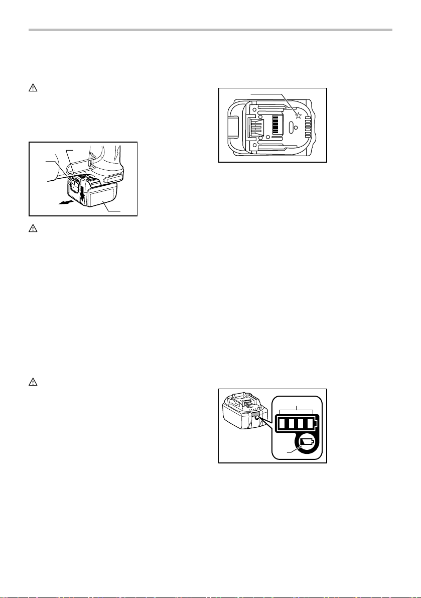
To remove the battery cartridge, slide it from the tool
while sliding the button on the front of the cartridge.
To install the battery cartridge, align the tongue on the
battery cartridge with the groove in the housing and slip
it into place. Insert it all the way until it locks in place with
a little click. If you can see the red indicator on the upper
side of the button, it is not locked completely.
CAUTION:
• Always install the battery cartridge fully until the
red indicator cannot be seen. If not, it may
accidentally fall out of the tool, causing injury to
you or someone around you.
• Do not install the battery cartridge forcibly. If the
cartridge does not slide in easily, it is not being
inserted correctly.
1. Red indicator
2. Button
3. Battery cartridge
3
Battery protection system
(Lithium-ion battery with star marking)
1
012128
Lithium-ion batteries with a star marking are equipped
with a protection system. This system automatically cuts
off power to the tool to extend battery life.
The tool will automatically stop during operation if the
tool and/or battery are placed under one of the following
conditions:
• Overloaded:
The tool is operated in a manner that causes
it to draw an abnormally high current.
In this situation, release the trigger switch on
the tool and stop the application that caused
the tool to become overloaded. Then pull the
trigger switch again to restart.
If the tool does not start, the battery is
overheated. In this situation, let the battery
cool before pulling the trigger switch again.
• Low battery voltage:
The remaining battery capacity is too low and
the tool will not operate. In this situation,
remove and recharge the battery.
1. Star marking
Indicating the remaining battery capacity
(Only for battery cartridges with "B" at the end of the
model number.)
1. Indicator lamps
1
2
015676
Press the check button on the battery cartridge to
indicate the remaining battery capacity. The indicator
lamps light up for few seconds.
2. CHECK button
5
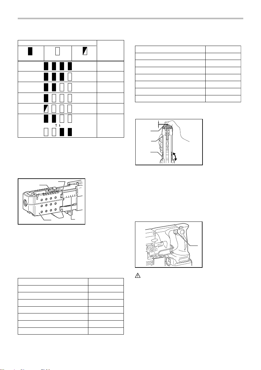
015658
Indicator lamps
Off
BlinkingLighted
Remaining
capacity
75% to 100%
50% to 75%
25% to 50%
0% to 25%
Charge the
battery.
The battery
may have
malfunctioned.
NOTE:
• Depending on the conditions of use and the
ambient temperature, the indication may differ
slightly from the actual capacity.
Setting for desired screw length
4
1
2
008123
There are 7 positive-lock screw length settings. To obtain
the desired setting, pull out the stopper base while
depressing the lever until you see the number of the
desired screw length (indicated on the label on feeder box)
appear to rest in the fenestella of stopper base. See the
table below for the relation between the number indicated
on the label on feeder box and the respective screw length.
For Models DFR540, DFR550
Number indicated on the labelScrew length
25
30
35
40
45
50
008239
55
1. Lever
2. Stopper base
3. Label on feeder
box
4. Fenestella
3
25 mm (1")
30 mm (13/16")
35 mm (1-3/8")
40 mm (1-9/16")
45 mm (1-3/4")
50 mm (2")
55 mm (2-3/16")
For Model DFR750
Number indicated on the labelScrew length
45 mm (1-3/4")
50 mm (2")
55 mm (2-3/16")
60 mm (2-3/8")
65 mm (2-9/16")
70 mm (2-3/4")
75 mm (2-15/16")
008240
45
50
55
60
65
70
75
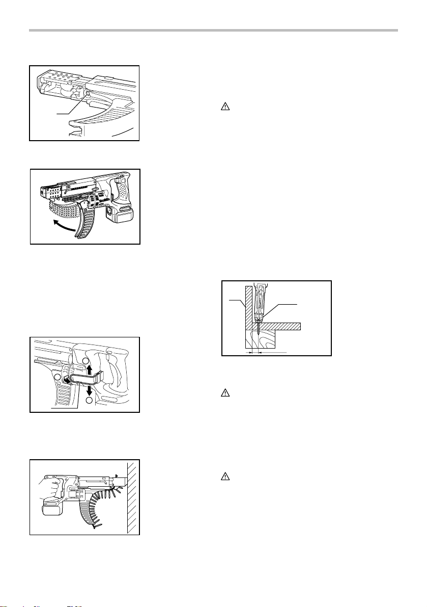
Adjusting the driving depth
5 mm
(3/16")
1
2
3
A
B
008280
Depress the stopper base as far as it will go. While
keeping it in this position, turn the adjusting knob until
the bit tip projects approx. 5 mm (3/16") from the stopper
base. Drive a trial screw. If the screw head projects
above the surface of the workpiece, turn the adjusting
knob in the A direction; if the screw head is counter-sunk,
turn the adjusting knob in the B direction.
1. Stopper base
2. Casing
3. Adjusting knob
Switch action
1. Switch trigger
1
008282
CAUTION:
• Before inserting the battery cartridge into the tool,
always check to see that the switch trigger
actuates properly and returns to the "OFF" position
when released.
To start the tool, simply pull the switch trigger. Release
the switch trigger to stop.
6
Reversing switch action
1
A
1. Reversing
switch lever
B
1
2
3
1. Plane bearing
2. Dust cover
3. Bit
008283
This tool has a reversing switch to change the direction
of rotation. Depress the reversing switch lever from the A
side for clockwise rotation or from the B side for
counterclockwise rotation.
When the reversing switch lever is in the neutral position,
the switch trigger cannot be pulled.
CAUTION:
• Always check the direction of rotation before
operation.
• Use the reversing switch only after the tool comes
to a complete stop. Changing the direction of
rotation before the tool stops may damage the tool.
• When not operating the tool, always set the
reversing switch lever to the neutral position.
ASSEMBLY
CAUTION:
• Always be sure that the tool is switched off and the
battery cartridge is removed before carrying out
any work on the tool.
Installing or removing the bit
Loosen the thumb screws which secure the casing. Pull
out the casing in the direction of the arrow.
1. Casing
2. Thumb screw
008286
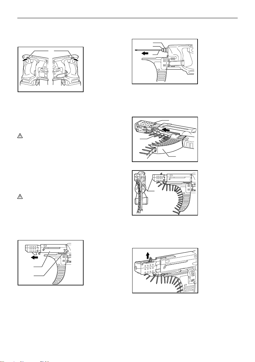
Installing screw strip
Insert the screw strip through the screw guide. Then
insert it through the feeder box until the first screw
reaches the position next to the driving position.
1
2
3
008290
1
008288
1. Feeder box
2. Screw strip
3. Screw guide
1. Driving position
Removing screw strip
To remove the screw strip, just pull it out in the direction of
the arrow. If you depress the reverse button, you can pull
out the screw strip in the reverse direction of the arrow.
1
2
008285
Press the dust cover toward the plane bearing and pull
out the bit. If the dust cover cannot be moved as far as
the plane bearing, try it again after turning the bit slightly.
To install the bit, insert it into the socket while turning it
slightly. After installing, always make sure that the bit is
securely held in place by trying to pull it out.
7
008281
1. Reverse button
1
008128
Folding screw guide
008289
Screw guide is foldable. Folding the screw guide allows
space used for storage to be minimal.
Carry hook
The carry hook is convenient for temporarily hooking the
tool. It can be installed on either side of the tool.
When removing the carry hook, widen it by pressing its
right ends ON BOTH SIDES in the directions of arrow (1)
and raise it in the direction of the arrow (2).
Switch on the tool by pulling the switch trigger. Hold the
tool squarely and firmly up against the driving surface. A
screw will be automatically carried to the driving position
and fastened.
CAUTION:
• Always check the bit carefully for wear before
driving operations. Replace a worn bit or poor
fastening may result.
• Always hold the tool squarely against the driving
surface. Holding it at an angle may damage the
screw heads and cause wear on the bit. This may
also lead to poor fastening.
• Always keep the tool firmly against the driving
surface until the driving is over. Failure to do so
may cause insufficient fastening of screws.
• Be careful not to drive a screw onto another screw
already fastened.
• Do not operate the tool without screws. It will
damage the driving surface.
• Do not apply oil or grease on the sliding surface of
the feeder box.
Driving in corner
1. Wall
1
2
2. Stopper base
1
2
1
008262
1
OPERATION
Driving operation
008263
1. Hook
008284
This tool can be used to drive at a position 15 mm (5/8")
away from the wall as shown in the figure.
CAUTION:
• Driving at a position closer than 15 mm (5/8") to the
wall or driving with the stopper base in contact with
the wall may damage the screw heads and cause
wear on the bit. This may also lead to poor
fastening of screws and malfunction of the tool.
MAINTENANCE
CAUTION:
• Always be sure that the tool is switched off and the
battery cartridge is removed before attempting to
perform inspection or maintenance.
• Never use gasoline, benzine, thinner, alcohol or
the like. Discoloration, deformation or cracks may
result.
8
15mm(5/8")
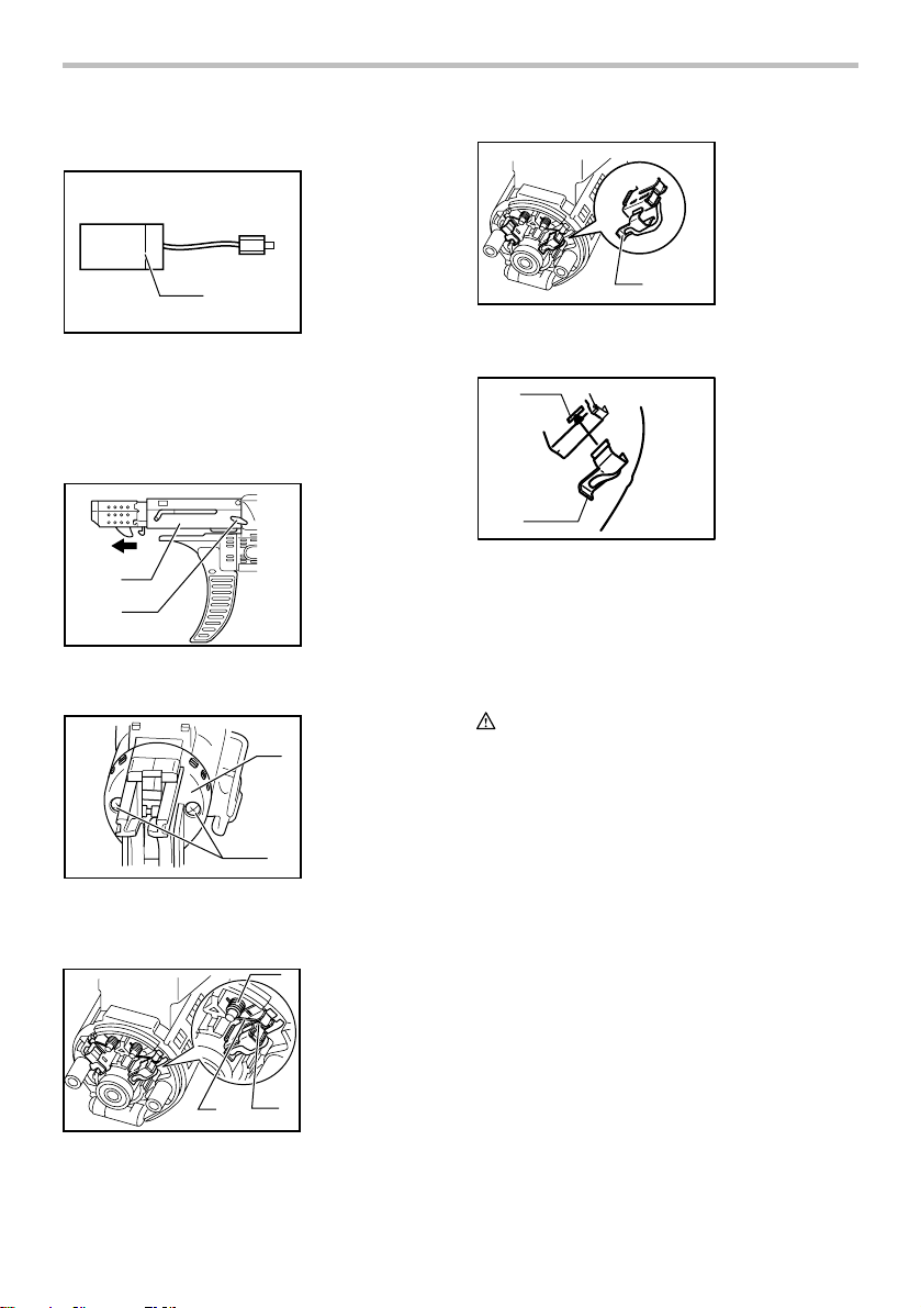
Replacing carbon brushes
1. Limit mark
1. Carbon brush
cap
1
006258
Replace when they wear down to the limit mark. Keep
the carbon brushes clean and free to slip in the holders.
Both carbon brushes should be replaced at the same
time. Use only identical carbon brushes.
Loosen the thumb screws which secure the casing. Pull
out the casing in the direction of the arrow.
1. Casing
2. Thumb screw
1
2
008285
Use a screwdriver to remove two screws then remove
the front cover.
1. Front cover
2. Screws
1
2
008287
Raise the arm part of the spring and then place it in the
recessed part of the housing with a slotted bit
screwdriver of slender shaft or the like.
1
1. Spring
2. Arm
3. Recessed part
1
006817
Make sure that the carbon brush caps have fit into the
holes in brush holders securely.
1
2
006304
1. Hole
2. Carbon brush
cap
Reinstall the front cover and tighten two screws securely.
To maintain product SAFETY and RELIABILITY, repairs,
any other maintenance or adjustment should be
performed by Makita Authorized or Factory Service
Centers, always using Makita replacement parts.
OPTIONAL ACCESSORIES
CAUTION:
• These accessories or attachments are
recommended for use with your Makita tool
specified in this manual. The use of any other
accessories or attachments might present a risk of
injury to persons. Only use accessory or
attachment for its stated purpose.
If you need any assistance for more details regarding
these accessories, ask your local Makita Service Center.
• Drywall screw strip
• Phillips bit
• Makita genuine battery and charger
• Plastic carrying case
NOTE:
• Some items in the list may be included in the tool
package as standard accessories. They may differ
from country to country.
3
2
006816
Use pliers to remove the carbon brush caps of the carbon
brushes. Take out the worn carbon brushes, insert the
new ones and replace the carbon brush caps in reverse.
9

MAKITA LIMITED ONE YEAR WARRANTY
Warranty Policy
Every Makita tool is thoroughly inspected and tested
before leaving the factory. It is warranted to be free of
defects from workmanship and materials for the period
of ONE YEAR from the date of original purchase.
Should any trouble develop during this one year period,
return the COMPLETE tool, freight prepaid, to one of
Makita’s Factory or Authorized Service Centers. If
inspection shows the trouble is caused by defective
workmanship or material, Makita will repair (or at our
option, replace) without charge.
This Warranty does not apply where:
repairs have been made or attempted by others:
repairs are required because of normal wear and
tear:
the tool has been abused, misused or improperly
maintained:
alterations have been made to the tool.
IN NO EVENT SHALL MAKITA BE LIABLE FOR ANY
INDIRECT, INCIDENTAL OR CONSEQUENTIAL
DAMAGES FROM THE SALE OR USE OF THE
PRODUCT. THIS DISCLAIMER APPLIES BOTH
DURING AND AFTER THE TERM OF THIS
WARRANTY.
MAKITA DISCLAIMS LIABILITY FOR ANY IMPLIED
WARRANTIES, INCLUDING IMPLIED WARRANTIES
OF "MERCHANTABILITY" AND "FITNESS FOR A
SPECIFIC PURPOSE," AFTER THE ONE YEAR TERM
OF THIS WARRANTY.
This Warranty gives you specific legal rights, and you
may also have other rights which vary from state to
state. Some states do not allow the exclusion or
limitation of incidental or consequential damages, so
the above limitation or exclusion may not apply to you.
Some states do not allow limitation on how long an
implied warranty lasts, so the above limitation may not
apply to you.
EN0006-1
10
 Loading...