

Page 1
T
ECHNICAL INFORMATION
Models No.
Description
DF030D (FD01*)
10.8V Cordless Driver Drill
* Model number for North and Central American
countries except Mexico and Guam
PRODUCT
P 1/ 4
L
CONCEPT AND MAIN APPLICATIONS
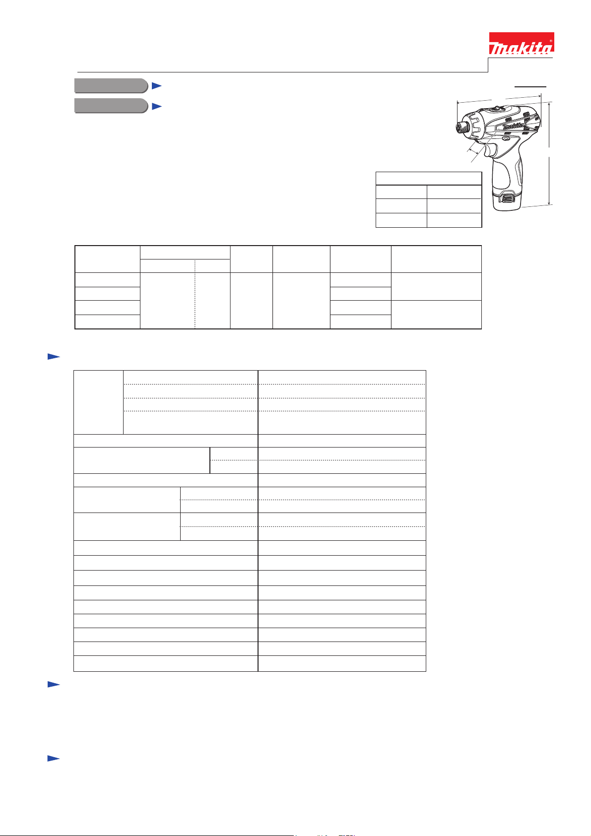
Model DF030D is a 10.8V cordless driver drill compact and lightweight
for easy handling, but featuring 2-speed gear selection with variable speed
in each range for a wide range of applications.
Uses new 10.8V Li-ion battery of stick type as a power unit.
This product is available in the following variations.
Model No.
DF030D
DF030DW
DF030DWE
DF030DWEW
The models also includes the accessories listed below in "Standard equipment".
Battery
type quantity
BL1013
(Li-ion 1.3Ah)
2
Charger
DC10WA
Specification
Type of cell
Voltage: V
Battery
Max. output: W
No load speed: min-1 = rpm
Driving shank: mm (")
Capacities: mm (")
Max. fastening torque:
N.m (in.lbs)
Electric brake
Variable speed control by trigger
Mechanical 2-speed
Reverse switch
LED job light
Net weight [with battery BL1013]: kg (lbs)
Capacity: Ah
Charging time (approx.): min.
Low
High
Steel
Wood
Soft joint
Hard joint
Plastic
carrying case
Yes
18 stages + drill modeTorque adjustment
Housing
color
Makita-blue
white
Makita-blue
white
Li-ion
10.8
1.3
50
with DC10WA
115
0 - 350
0 - 1,300
6.35 (1/4) Hex
10 (3/8)
21 (13/16)
14 (120)
24 (210)
0.5 - 3.5 (4 - 30)Clutch torque setting: N.m (in.lbs)
22 (200)Lock torque: N.m (in.lbs)
Yes
Yes
Yes
Yes
Yes
0.88 (1.9)
W
Dimensions: mm (")
Length (L) 157 (6-3/16)
Width (W)
Height (H)
All countries except
the four listed above
53 (2-1/16)
183 (7-1/4)
Offered to
USA, Canada
Mexico, Panama
H
Standard equipment
Phillips bit 2-50 (double-end) ........ 1 pc (for countries using M-type spindle)
Phillips bit 2-45 (double-end) ........ 1 pc (for countries using N-type spindle)
Holster ............................................ 1 pc
Note: The standard equipment for the tool shown above may differ by country.
Optional accessories
Driver bits, Socket bits, Hex shank drill bits for wood, Hex shank drill bits for steel, Bit piece,
Drill chuck, Charger DC10WA, Battery BL1013
Page 2
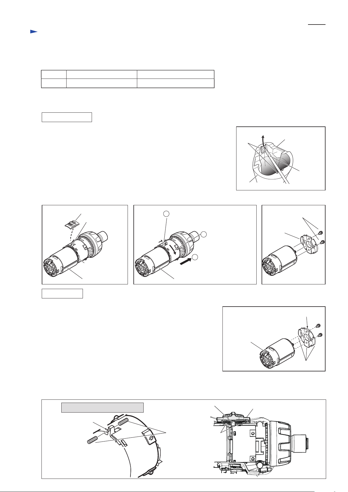
1) Remove two Set plates with which Handles (L) and (R) are assembled to one
another as follows:
Insert a small slotted screwdriver through the punched hole of Set plate and
move Set plate in the direction of the arrow using the screwdriver. (Fig.1)
2) Remove Housing (R) from Housing (L) by loosening six Bind PT3x6 tapping
screws.
3) Remove Speed change lever assembly from Gear assembly. (Fig. 2)
4) Remove DC motor from Gear assembly as illustrated in Fig. 3
5) Separate DC motor from Bracket by loosening two M3x6 Pan head screws.
(Fig. 4)
1) Fix Motor bracket to DC motor with two M3x6 Pan head screws.
Note: Align the red marking on DC motor with non-convex portion of
Motor bracket. (Fig. 5)
2) Fix Gear assembly to DC motor with bracket and turn Gear assembly
clockwise.
Note: Align the change lever of Gear assembly with the red marking on
DC motor. (Fig. 3)
3) Fix Speed change lever assembly to the change lever of Gear assembly as
illustrated in Fig. 2.
Note: Set the change lever of Gear assembly in place between two
Compression springs 4 on the reverse side of Speed change lever
assembly, and insert the emboss of the change lever into one of
Compression spring 4. (Fig. 6)
Repair
P 2/ 4
[2] DISASSEMBLY/ASSEMBLY
[3]-1. DC Motor, Gear Assembly, Speed Change Lever Assembly
Fig. 2 Fig. 4Fig. 3
DISASSEMBLING
ASSEMBLING
[1] NECESSARY REPAIRING TOOLS
CAUTION: Remove the bit and the battery from the machine for safety before
repair/ maintenance in accordance with the instruction manual!
DescriptionCode No. Use for
1R291 Removing/ Installing Bit sleeve
Fig. 1
Handle (R)
Handle (L)
small slotted
screwdriver
Set plate
(2pcs.)
Retaining ring S and R pliers
Speed change lever assembly
convex portion of
Motor bracket
change lever of
Gear assembly
change lever of
Gear assembly
Emboss of change lever
of Gear assembly
DC motor
Turn Gear assembly
counterclockwise.
Pull out Gear assembly
from DC motor with
Bracket.
DC motor
Motor bracket
M3x6 Pan head screws
(2pcs.)
1
Shift the change lever of Gear
assembly to the high speed position.
2
3
Fig. 5
Fig. 6
non-convex portion
Compression spring 4
Speed change lever assembly
red marking on
terminal of positive
pole
convex portions
Viewed from the upper position
Page 3

(4) After installing the assembled parts in place of Housing L, shift Speed change lever assembly to either low speed
position or high speed position.
(5) Fixing Housing (R) to Housing (L) with six Bind PT3x16 tapping screws.
(6) Insert two Set plates in place. (Fig. 1)
Set Leaf spring in place. (Fig. 8)
Note: Do not face the center edge of Leaf spring to Housing L.
Link the notch of F/R change lever and the protrusion of Switch,
then install them in Housing L. (Fig. 9)
Repair
P 3/ 4
[2] DISASSEMBLY/ASSEMBLY
[3]-1. DC Motor, Gear Assembly, Speed Change Lever Assembly (cont.)
ASSEMBLING
Fig. 9
Fig. 8
Fig. 7
[3]-3. Assembling Leaf Spring
[3]-4. Assembling F/R Change Lever
[3]-2. Disassembling Bit Holder of Gear Assembly
Sleeve
Ring spring 10
(1) While pushing the top of sleeve by your thumb to prevent Compression spring 13
from popping out from Bit holder, expand Ring spring 10 using 1R291 and raise
the opposite of the expanded Ring spring 10 by your index finger. (Fig. 7)
(2) Ring spring 10 can be removed.
And Flat washer 11, Compression spring 13, Bit sleeve and Steel ball 3 (2pcs.)
can be removed.
1R291
Leaf spring
center edge
Housing L
notch of F/R change lever
protrusion of Switch
Circuit diagram
Fig. D-1
SwitchTerminal
White
DC motor
red marking
Red
Color index of lead wires' sheath
Black
+ +
- -
M1
M2
LED
Page 4

P 4/ 4
Wiring diagram
Fig. D-2
Fig. D-3
Pay attention to the directions of lead wires and connect Flag receptacles
to electrical parts.
Refer to the following illustration.
Fig. D-4
Before installing Switch in Housing R, route Lead wires as illustrated below and connect two Connectors.
Do not ride their Lead wires on ribs.
Route Lead wires between ribs. Insert Connectors between
their Lead wire holders.
Bend the terminals of DC motor
as illustrated.
Flag receptacles and
Lead wires have to
be far from DC motor.
Do not ride them
on the ribs.
Lead wires holders
Do not ride Lead wires on their embosses.
Face the glue-attached portion of LED
to DC motor side.
Terminal DC motor
Connector
Lead wire holders
LED
Lead wires in this area
must be tight.
red marking
Connector
(To Switch)
 Loading...