

Page 1
P 1/ 6
Model No.
Description
CONCEPT AND MAIN APPLICATIONS
Specification
Standard equipment Optional accessories
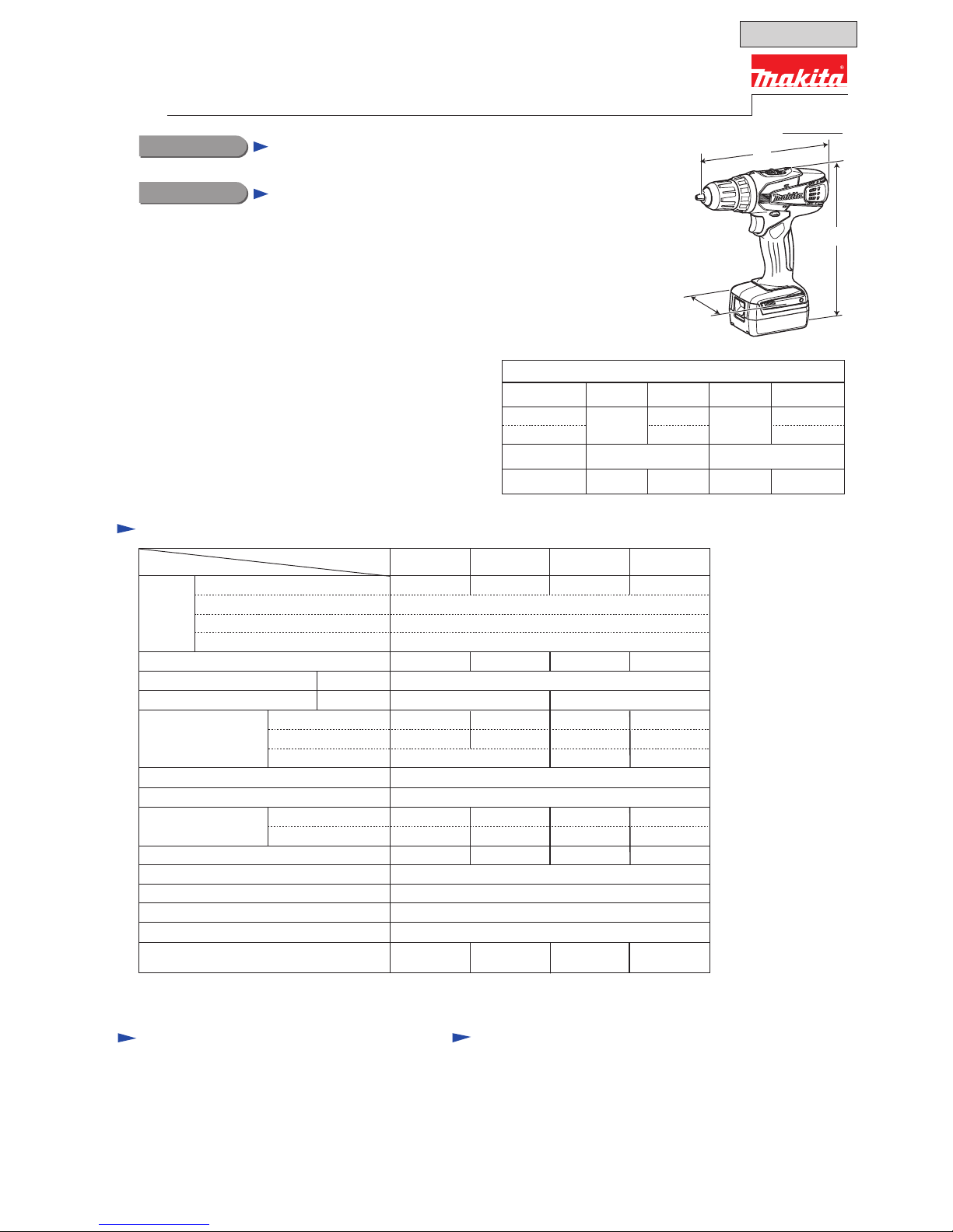
Dimensions: mm (")
Width (W)
Height (H)
Length (L)
Length (L)*
2
*2 Length for North and Central American countries
Model No. DF347D DF457D HP347D
198 (7-3/4)
83 (3-1/4)
235 (9-1/4)
216 (8-1/2)
240 (9-1/2)
221 (8-3/4)
83 (3-1/4)
235 (9-1/4)
239 (9-3/8)
228 (9) 246 (9-11/16)
240 (9-1/2)
Note: The standard equipment for the tool
shown above may vary by country.
Battery
Chuck capacity: mm (")
Capacity: mm (")
Electric brake
Variable speed control
Mechanical speed control
Reversing switch
Max. fastening
torque: N.m (in.lbs)
Torque setting
Steel
Wood
Soft joint
Hard joint
No load speed: min-
1=rpm
Cell
Voltage: V
Capacity: Ah
Low/ High
Charger DC18WA
Battery BL1411G for DF347D/ HP347D
Battery BL1811G for DF457D/ HP457D
Drill bits for wood
Drill bits for steel
Drill bits for masonry for HP347D/ HP457D
Driver bits
Battery BL1411G for DF347D/ HP347D
Battery BL1811G for DF457D/ HP457D
Charger DC18WA
Battery cover
+- Bit 2-65
Plastic carrying case
Weight according to
EPTA-Procedure 01/2003: kg (lbs)
Li-ion
Charging time (approx.): min.
60 with DC18WA
DF347D DF457D HP347D HP457D
1.1
Yes
Yes
Yes (2 speed)
Clutch torque setting: N.m (in.lbs)
Lock torque: N.m (in.lbs)
1.0 - 4.0 (9 - 35)
23 (200) 38 (340) 38 (340)23 (200)
Yes
1.4 (3.2)
*3 1.7 (3.7)*4 1.5 (3.3)*3 1.7 (3.8)*4
10 (3/8)
25 (1)
Masonry N/A
13 (1/2)
36 (1-7/16)
10 (3/8)
25 (1)
13 (1/2)
10 (3/8) 13 (1/2)
36 (1-7/16)
16 stage + drill mode
30 (270)
15 (130)
30 (270)
15 (130)
42 (370)
24 (210)
42 (370)
24 (210)
0 - 400/ 0 - 1,400
Impacts per min.: min-
1=ipm Low/ High N/A 0 - 6,000/ 0 - 21,000
10 (3/8) 13 (1/2)
10 (3/8) 13 (1/2)
These models have been developed to use 1.1Ah Li-ion
batteries (BL1411G/ BL1811G) and charger (DC18WA)
newly designed to provide cost-competitive advantage to
Makita brand cordless tools.
The specification difference between these models are:
DF347D/ 14.4V Cordless driver drill
DF457D/ 18V Cordless driver drill
HP347D/ 14.4V Cordless hammer driver drill
HP457D/ 18V Cordless hammer driver drill
PRODUCT
(model DF347D)
*3 with Battery BL1411G
*4 with Battery BL1811G
DF347D/ DF457D
HP347D/ HP457D
Cordless Driver Drills 14.4V/ 18V
Cordless Hammer Driver Drills 14.4V/ 18V
HP457D
Model No.
Specification
14.4 18 14.4 18
H
L
W
T
ECHNICAL INFORMATION
OFFICIAL USE
for ASC & Sales Shop
Page 2
Repair
CAUTION: Repair the machine in accordance with “Instruction manual” or “Safety instructions”.
[2] DISASSEMBLY/ASSEMBLY
[2]-1. Single sleeve drill chuck
DISASSEMBLING
ASSEMBLING
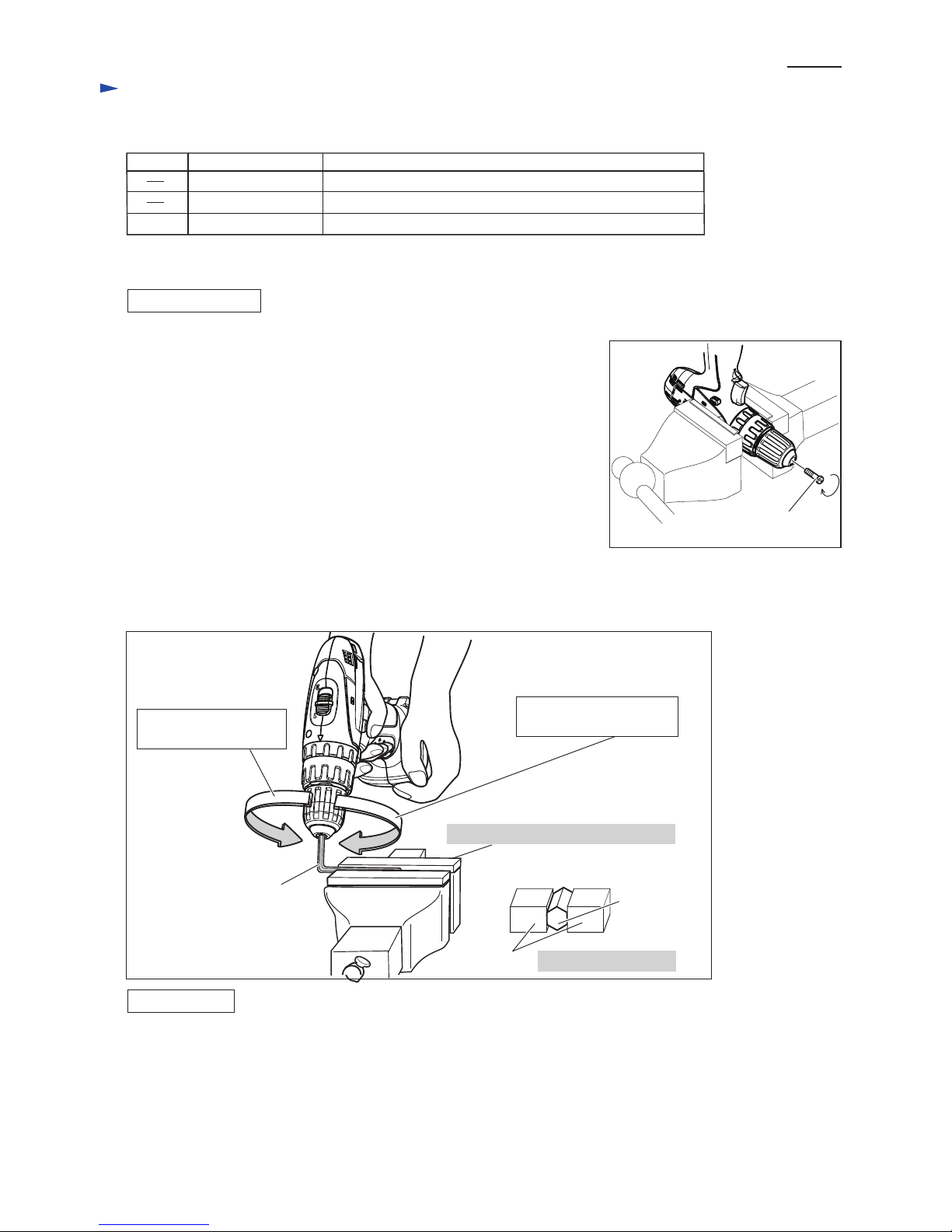
Fig. 1
Fig. 2
M6x22 - Flat head screw
(left-hand screw)
Note: It is required to remove Drill chuck when replacing Gear assembly,
but you need not when replacing the parts that are independent of
Gear assembly.
(1) Open the jaws of Drill chuck fully, and turn M6x22 - Flat head screw
(left-handed and threadlocker coated) clockwise with Slotted screwdriver.
When it is difficult to remove the screw, use Vise and Impact driver. (Fig. 1)
(2) Set the machine to drill mode, low gear mode and reverse rotation mode.
(3) Hold the long side of Hex wrench 8 in Vise and secure the short side to Drill
chuck firmly as drawn in Fig. 2.
(3) Pull Switch trigger slowly.
Important:
Be sure to hold the grip of Machine tightly with sufficient counterclockwise*
force against clockwise* recoil force of the machine.
Note: The rotational direction marked with * is viewed from operator.
(4) Spindle rotates counterclockwise* and consequently Drill chuck is removed from spindle.
When the above way is not effective, use 1R359 to remove Drill chuck. Refer to Makita repair tool list.
(1) Seat Drill chuck on Spindle.
(2) Set the machine to Drill mode, Low gear mode and Forward rotation mode.
(3) Hold the long side of Hex wrench 10 in Vise and secure the short side to Drill chuck firmly. And then tighten Spindle
into Drill chuck by pulling the trigger of Switch slowly at first and to the full speed in one second not to give impacts
carefully.
Note: Release the trigger of Switch just after Spindle is locked. Do not keep on pulling the trigger for longer
than one second.
(4) Fasten Drill chuck to Spindle with M6x22 - Flat head screw by turning it counterclockwise.
Note: If you reuse the screw removed from Drill chuck, apply an appropriate amount of adhesive
(ThreeBond 1321B/ 1342 or Loctite 242) to the thread for secure fastening.
Hold the flats of this long end in vise.
Do not hold the edges.
Viewed from the front side
Hex wrench 8
P 2/ 6
[1] NECESSARY REPAIRING TOOLS
Code No. Description Use for
Hex wrench 8 removing / assembling Drill chuck
removing Drill chuckPlastic hammer
removing Drill chuck (when the following way is not effective)Chuck removing tool1R359
Hex wrench 8
Vise
Fig. 2
Counterclockwise* force
to be applied by operator
Clockwise* recoil force
of the machine
Page 3
[3] DISASSEMBLY/ASSEMBLY
[3]-2. DC motor
DISASSEMBLING
ASSEMBLING
It is not necessary to remove Drill chuck from Gear assembly when replacing DC motor.
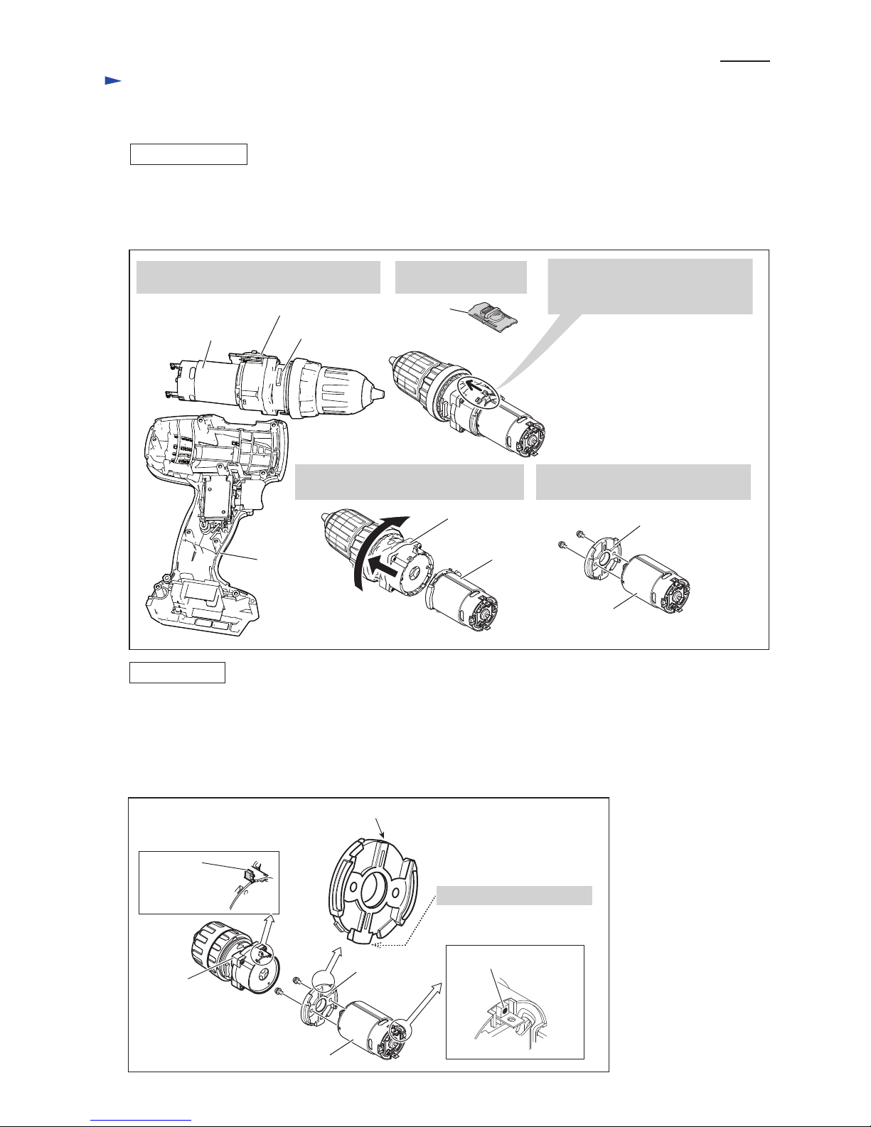
(1) Remove nine 3x16 Tapping screws and Housing R from Housing L.
(2) DC motor can be replaced as drawn in Fig. 3.
Fig. 3
Fig. 4
1. Disassemble DC motor, Gear assembly
with Speed change lever from Housing L.
2. Disassemble Speed
change lever.
3. Slide the lever of Gear assembly
to Drill chuck side.
(Set the hook to low gear mode.)
DC motor
Gear assembly
Speed change lever
Housing L
Speed change
lever
4. Pull off Gear assembly while turning it
clockwise viewed from DC motor side.
5. Remove Motor bracket and two Pan
head screws from DC motor.
Gear assembly
DC motor
Motor bracket
DC motor
Motor bracket
DC motor
Do not face this projection.
red mark on DC motor
Gear assembly
Flat side (No projection side)
lever of
Gear assembly
Do the reverse of the disassembling steps.
The following portions of DC motor, Motor bracket and Gear assembly have to face the same side. (Fig. 4)
• red mark (designated as plus terminal) on DC motor
• flat side (No projection side) of Motor bracket
• lever of Gear assembly
Repair
P 3/ 6
Page 4
[3] DISASSEMBLY/ASSEMBLY
[3]-3. Speed change lever assembly
DISASSEMBLING
ASSEMBLING
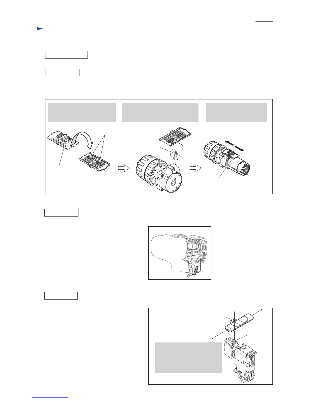
Refer to Fig. 5.
Fig. 5
Do the reverse of the disassembling steps.
Assemble Speed change lever to Gear assembly as drawn in Fig. 5.
[3]-4. Leaf spring
3. Slide Speed change lever to
low gear mode or high gear
mode after assembling.
Compression
spring 4 (2pcs.)
Speed change lever
ass’y
1. Make sure that Compression
springs 4 (2pcs.) are set in place
in Speed change lever ass’y.
Projection of
lever of Gear
assembly
2. Fit the projection of lever of Gear
assembly into Compression spring 4
in Speed change lever ass’y.
Speed change lever ass’y
Low gear mode
High gear mode
Leaf spring
Housing L
Set Leaf spring in place in Housing L. (Fig. 6).
Fig. 6
Fig. 7
ASSEMBLING
Repair
P 4/ 6
[3]-5. F/R change lever
projection
of Switch
Hook F/R change lever with
the projection of Switch,
and insert the ends of F/R change
lever to the holes of Housing L
and R.
hook of
F/R change lever
F/R Change lever can be assembled to Switch as
drawn in Fig. 7.
ASSEMBLING
Page 5
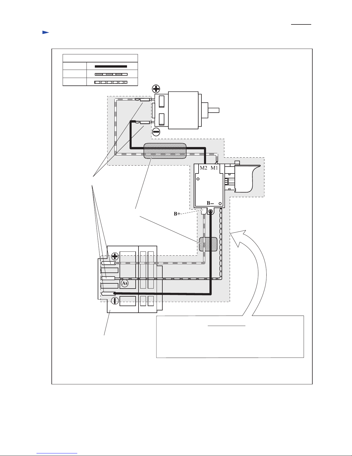
Circuit diagram
Color index of lead wires' sheath
Black
Red
Yellow
DC Motor
Line filters
Flag receptacles
Terminal
Part No. 638862-2: with Line filters and Flag receptacles
Part No. 638887-6: without Line filters and with Flag receptacles
Note: The difference of the above specifications is based on
the regulations by country or area.
Switch unit
Fig. D-1
Switch
P 5/ 6
(Housing L side)
(Housing L side)
(Housing R side)
Page 6
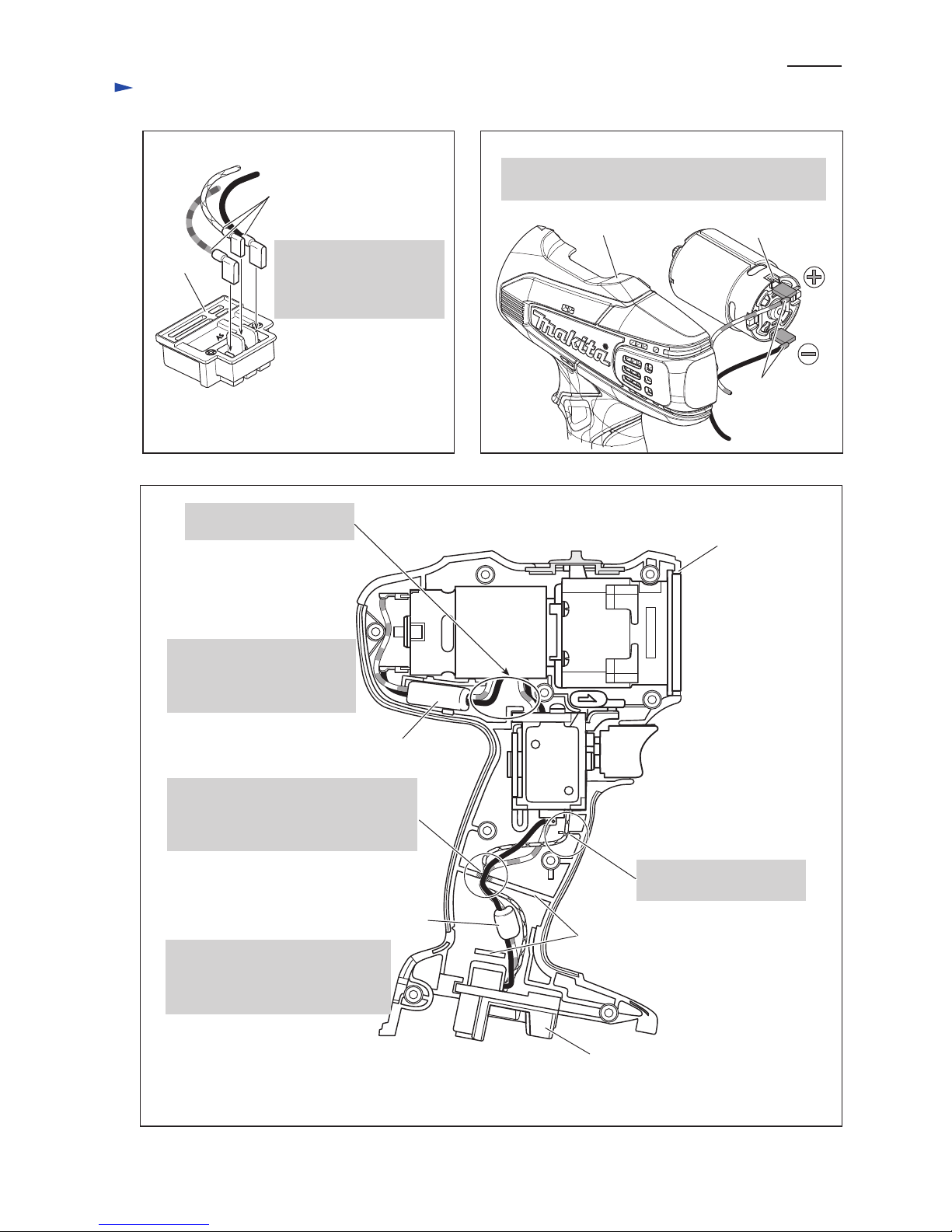
Wire connecting portions
of Flag receptacles
Connect Flag receptacles so that the wire connecting
portions face Housing L side.
Terminal
Connect Flag receptacles
so that the wire connecting
portions face +, - and AS
marks on Terminal.
Red markHousing L
Wire connecting
portions of
Flag receptacles
DC motor
Switch
Housing L
Ribs
Put the slacks of Lead wires
in this space.
Pass Lead wires (black, red)
through ø10-30mm Line filter,
and put the line filter as drawn
right.
Pass Lead wires (black, red) through
ø10-11 mm Line filter, and put
the line filter in the place between
Ribs.
Terminal
Line filter
(Diameter ø10-30 mm)
Line filter
(Diameter ø10-11 mm)
Fig. D-2
Fig. D-3
Fix Lead wires in Lead wire holder here.
Be sure to put Lead wire (yellow) to
the bottom and pile Lead wires (black,.
red) on it.
Fix the Lead wire (yellow)
in Lead wire holder here.
Note: Line fiters are not used for some countries.
Fig. D-4
Wiring diagram
P 6/ 6
 Loading...