

Page 1
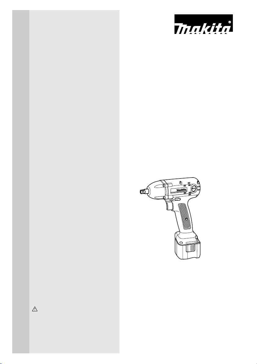
Cordless Impact
Wrench
Equipped with Electric Brake
MODEL BTW072
INSTRUCTION MANUAL
WARNING:
For your personal safety, READ and UNDERSTAND before using.
SAVE THESE INSTRUCTIONS FOR FUTURE REFERENCE.
001278
Page 2
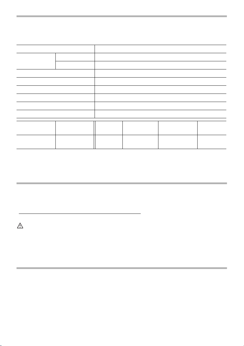
SPECIFICATIONS
Model BTW072
Capacities
Square drive 9.5 mm (3/8”)
No load speed (RPM) 0 - 2,500/min.
Impacts per minute 0 - 3,000
Max. fastening torque 65 N.m (46.8 ft.lbs)
Overall length 166 mm (6-9/16”)
Standard bolt M5 - M12 (3/16” - 1/2”)
High tensile bolt M5 - M10 (3/16” - 3/8”)
Net weight 1.09 kg (2.4 lbs)
Battery
Cartridge
B9017A 9.6 V DC14SA
• Manufacturer reserves the right to change specifications without notice.
• Specifications may differ from country to country.
Voltage
Battery
Charger
Input Output
A.C. only
50 Hz - 60 Hz
D.C.
7.2 V - 14.4 V
Charging
time
30 min.
GENERAL SAFETY RULES USA003-1
(FOR All BATTERY OPERATED TOOLS)
WARNING:
Read and understand all instructions. Failure to follow all
instructions listed below, may result in electric shock, fire and/or
serious personal injury.
SAVE THESE INSTRUCTIONS
Work A re a
1. Keep your work area clean and well lit.
Cluttered benches and dark areas invite accidents.
2
2. Do not operate power tools in explosive
atmospheres, such as in the presence of
flammable liquids, gases, or dust. Power
tools create sparks which may ignite the dust
or fumes.
Page 3

3. Keep bystanders, children, and visitors
away while operating a power tool. Distrac-
tions can cause you to lose control.
Electrical Safety
4. A battery operated tool with integral batteries or a separate battery pack must be
recharged only with the specified charger
for the battery. A charger that may be suit-
able for one type of battery may create a risk
of fire when used with another battery.
5. Use battery operated tool only with specifically designated battery pack. Use of any
other batteries may create a risk of fire.
Personal Safety
6. Stay alert, watch what you are doing, and
use common sense when operating a
power tool. Do not use tool while tired or
under the influence of drugs, alcohol, or
medication. A moment of inattention while
operating power tools may result in serious
personal injury.
7. Dress properly. Do not wear loose clothing or jewelry. Contain long hair. Keep
your hair, clothing, and gloves away from
moving parts. Loose clothes, jewelry, or long
hair can be caught in moving parts.
8. Avoid accidental starting. Be sure switch
is in the locked or off position before
inserting battery pack. Carrying tools with
your finger on the switch or inserting the battery pack into a tool with the switch on invites
accidents.
9. Remove adjusting keys or wrenches
before turning the tool on. A wrench or a
key that is left attached to a rotating part of
the tool may result in personal injury.
10. Do not overreach. Keep proper footing
and balance at all times. Proper footing and
balance enable better control of the tool in
unexpected situations.
11. Use safety equipment. Always wear eye
protection. Dust mask, non-skid safety
shoes, hard hat, or hearing protection must
be used for appropriate conditions.
Tool Use and Care
12. Use clamps or other practical way to
secure and support the workpiece to a
stable platform. Holding the work by hand or
against your body is unstable and may lead
to loss of control.
13. Do not force tool. Use the correct tool for
your application. The correct tool will do the
job better and safer at the rate for which it is
designed.
14. Do not use tool if switch does not turn it
on or off. A tool that cannot be controlled
with the switch is dangerous and must be
repaired.
15. Disconnect battery pack from tool or
place the switch in the locked or off position before making any adjustments,
changing accessories, or storing the tool.
Such preventive safety measures reduce the
risk of starting the tool accidentally.
16. Store idle tools out of reach of children
and other untrained persons. Tools are
dangerous in the hands of untrained users.
17. When battery pack is not in use, keep it
away from other metal objects like: paper
clips, coins, keys, nails, screws, or other
small metal objects that can make a connection from one terminal to another.
Shorting the battery terminals together may
cause sparks, burns, or a fire.
18. Maintain tools with care. Keep cutting
tools sharp and clean. Properly maintained
tools with sharp cutting edge are less likely to
bind and are easier to control.
19. Check for misalignment or binding of
moving parts, breakage of parts, and any
other condition that may affect the tool’s
operation. If damaged, have the tool serviced before using. Many accidents are
caused by poorly maintained tools.
20. Use only accessories that are recommended by the manufacturer for your
model. Accessories that may be suitable for
one tool may create a risk of injury when
used on another tool.
3
Page 4

SERVICE
21. Tool service must be performed only by
qualified repair personnel. Service or main-
tenance performed by unqualified personnel
may result in a risk of injury.
22. When servicing a tool, use only identical
replacement parts. Follow instructions in
the Maintenance section of this manual.
Use of unauthorized parts or failure to follow
Maintenance instructions may create a risk of
shock or injury.
SPECIFIC SAFETY RULES USB025-2
DO NOT let comfort or familiarity with product (gained from
repeated use) replace strict adherence to cordless impact
wrench safety rules. If you use this tool unsafely or incorrectly,
you can suffer serious personal injury.
1. Hold tool by insulated gripping surfaces
when performing an operation where the
cutting tool may contact hidden wiring.
Contact with a “live” wire will also make
exposed metal parts of the tool “live” and
shock the operator.
2. Be aware that this tool is always in an
operating condition, because it does not
have to be plugged into an electrical outlet.
3. Wear ear protectors.
4. Check the socket carefully for wear,
cracks or damage before installation.
5. Hold the tool firmly.
6. Always be sure you have a firm footing.
7. Be sure no one is below when using the
tool in high locations.
8. The proper fastening torque may differ
depending upon the kind or size of the
bolt. Check the torque with a torque
wrench.
SAVE THESE INSTRUCTIONS
WARNING:
MISUSE or failure to follow the safety rules stated in this
instruction manual may cause serious personal injury.
4
Page 5

SYMBOLS USD302-1
The followings show the symbols used for tool.
V .......................volts
................... direct current
................... no load speed
n
˚
.../min................revolutions or reciprocation per
minute
................number of blow
IMPORTANT SAFETY INSTRUCTIONS FOR
CHARGER & BATTERY CARTRIDGE
1. SAVE THESE INSTRUCTIONS- This manual contains important safety and operating instructions for battery charger.
2. Before using battery charger, read all
instructions and cautionary markings on
(1) battery charger, (2) battery, and (3)
product using battery.
3. CAUTION - To reduce risk of injury, charge
only MAKITA rechargeable batteries
marked on the charger label. Other types
of batteries may burst causing personal
injury and damage.
4. Do not expose charger to rain or snow.
5. Use of an attachment not recommended
or sold by the battery charger manufacturer may result in a risk of fire, electric
shock, or injury to persons.
Table 1: RECOMMENDED MINIMUM AWG SIZE FOR EXTENSION CORDS FOR BATTERY CHARGERS
6. To reduce risk of damage to electric plug
and cord, pull by plug rather than cord
when disconnecting charger.
7. Make sure cord is located so that it will
not be stepped on, tripped over, or otherwise subjected to damage or stress.
8. An extension cord should not be used
unless absolutely necessary. Use of
improper extension cord could result in a
risk of fire and electric shock. If extension
cord must be used, make sure:
a. That pins on plug of extension cord
are the same number, size, and shape
as those of plug on charger;
b. That extension cord is properly wired
and in good electrical condition; and
c. That wire size is at least as large as
the one specified in the table below.
USC002-3
Length of Cord (Feet) 25 50 100 150
AWG Size of Cord 18 18 18 16
9. Do not operate charger with damaged
cord or plug - replace them immediately.
10. Do not operate charger if it has received a
sharp blow, been dropped, or otherwise
damaged in any way; take it to a qualified
serviceman.
5
Page 6

11. Do not disassemble charger or battery
cartridge; take it to a qualified serviceman
when service or repair is required. Incorrect reassembly may result in a risk of
electric shock or fire.
12. To reduce risk of electric shock, unplug
charger from outlet before attempting any
maintenance or cleaning. Turning off controls will not reduce this risk.
13. The battery charger is not intended for
use by young children or infirm persons
without supervision.
14. Young children should be supervised to
ensure that they do not play with the battery charger.
15. If operating time has become excessively
shorter, stop operating immediately. It
may result in a risk of overheating, possible burns and even an explosion.
16. If electrolyte gets into your eyes, rinse
them out with clear water and seek medical attention right away. It may result in
loss of your eyesight.
ADDITIONAL SAFETY RULES FOR CHARGER &
BATTERY CARTRIDGE
1. Do not charge Battery Cartridge when
temperature is BELOW 10°C (50°F) or
ABOVE 40°C (104°F).
2. Do not attempt to use a step-up transformer, an engine generator or DC power
receptacle.
3. Do not allow anything to cover or clog the
charger vents.
4. Do not short the battery cartridge:
(1) Do not touch the terminals with any
conductive material.
(2) Avoid storing battery cartridge in a
container with other metal objects
such as nails, coins, etc.
(3) Do not expose battery cartridge to
A battery short can cause a large current
flow, overheating, possible burns and
even a breakdown.
5. Do not store the tool and Battery Cartridge in locations where the temperature
may reach or exceed 50°C (122°F).
6. Do not incinerate the Battery Cartridge
even if it is severely damaged or is completely worn out. The battery cartridge can
explode in a fire.
7. Be careful not to drop, shake or strike battery.
SAVE THESE INSTRUCTIONS
6
water or rain.
Page 7

SYMBOLS
The following show the symbols used for the charger. Be sure that you understand their
meaning before use.
.......... Ready to charge
............. Charging
............. Charging complete
...........Delay charge (Cooling)
........Defective battery
....Conditioning
...........Cooling abnormality
7
Page 8

FUNCTIONAL
DESCRIPTION
2
1. Battery cartridge
2. Button
1
2
1. Battery cartridge
2. Terminal cover
3. Charging lights
4. Battery charger
CAUTION:
• Always be sure that the tool is switched off and the
battery cartridge is removed before adjusting or
checking function on the tool.
001251
Installing or removing battery cartridge
• To remove the battery cartridge, withdraw it from the tool
while pressing the buttons on both sides of the cartridge.
• To insert the battery cartridge, align the tongue on the
battery cartridge with the groove in the housing and slip
1
it into place. Always insert it all the way until it locks in
place with a little click. If not, it may accidentally fall out
of the tool, causing injury to you or someone around you.
• Do not use force when inserting the battery cartridge. If
the cartridge does not slide in easily, it is not being
inserted correctly.
001253
Charging
1. Plug the battery charger into the proper AC voltage
source. Two charging lights will flash in green color
3
repeatedly.
2. Insert the battery cartridge into charger until it stops
4
adjusting to the guide of charger. Terminal cover of
charger can be opened with inserting and closed with
pulling out the battery cartridge.
3. When the battery cartridge is inserted, the charging light
color will change from green to red and charging will
begin. The charging light will keep lighting up lit steadily
during charging. One red charging light indicates
charged condition in 0 - 80% and two red ones indicates
80 - 100%.
4. With finish of charge, the charging lights will change
from two red ones to two green ones.
5. If you leave the battery cartridge in the charger after the
charging cycle is complete, the charger will switch into
its “trickle charge (maintenance charge)” mode which
will last approximately 24 hours.
6. After charging, unplug the charger from the power
source.
8
Page 9

NOTE:
• The battery charger is for charging Makita battery
cartridge. Never use it for other purposes or for other
manufacturer’s batteries.
• When you charge a new battery cartridge or a battery
cartridge which has not been used for a long period of
time, it may not accept a full charge. This is a normal
condition and does not indicate a problem. You can
recharge the battery cartridge fully after discharging it
completely and recharging a couple of times.
• If you charge a battery cartridge from a just operated tool
or battery cartridge which has been left in a location
exposed to direct sunlight for a long time, the charging
light may flash in red color. If this occurs, wait for a while.
Charging will begin after the battery cartridge is cooled
by the cooling fan installed in the charger. When the
temperature on battery is more than approx. 70°C, two
charging lights may flash in red color, and when approx.
50°C - 70°C, one charging light in red color.
• If the charging light flashes alternately in green and red
color, charging is not possible. The terminals on the
charger or battery cartridge are clogged with dust or the
battery cartridge is worn out or damaged.
• Any of the following conditions indicates damage to the
charger and/or battery cartridge. Ask your Makita
Authorized or Factory Service Center to check them.
(1) The charging light does not flash (green) when the
battery charger is plugged into a power source.
(2) The charging light does not light up or flash (red)
when the battery is inserted in the charger port.
(3) Charging is not completed at even more than two
hours after red light comes ON at start of charging.
Conditioning charge
Conditioning charge can extend the life of battery by automatically searching the optimum charging condition for the
batteries in every situations.
The battery employed in the following conditions repeatedly,
will be worn out shortly, and yellow warning light may flash.
1. Recharge of battery with its high temperature
2. Recharge of battery with its low temperature
9
Page 10

3. Recharge of full charged battery
4. Over-discharge of battery (continue to discharge battery
in spite of down of power.)
5. Recharge under broken cooling system
The charging time of such battery is longer than usual.
Trickle charge (Maintenance charge)
If you leave the battery cartridge in the charger to prevent
spontaneous discharging after full charge, the charger will
switch into its “trickle charge (maintenance charge)” mode
and keep the battery cartridge fresh and fully charged.
Tips for maintaining maximum battery life
1. Charge the battery cartridge before completely discharged.
Always stop tool operation and charge the battery cartridge when you notice less tool power.
2. Never recharge a fully charged battery cartridge.
Overcharging shortens the battery service life.
3. Charge the battery cartridge with room temperature at
10°C - 40°C (50°F - 104°F).
Let a hot battery cartridge cool down before charging it.
4. Charge the Nickel Metal Hydride battery cartridge when
you do not use it for more than six months.
Refresh charging
Refreshing adapter (optional accessory) can refresh an inactive battery cartridge.
• Refresh charging should be done once a week.
• When you charge a new battery cartridge or a battery
cartridge that has not been used for a long time, it may
not accept a full charge. In this case, refresh charging
must be done. The battery cartridge my decrease the
tool performance, because the chemical substance of
the battery cartridge is inactive.
10
Page 11

001254
Indicating lamp
(C) E F
orange
Indicating lamp
EF
orange
1
1. Switch trigger
Capacity
80% - 100%
60% - 80%
40% - 60%
10% - 40%
0% - 10%
Capacity
80% - 100%
60% - 80%
40% - 60%
10% - 40%
0% - 10%
001255
Checking the remaining battery capacity
When charging
When the charging begins, the first (far left) indicating lamp
begins to flicker. Then, as charging proceeds, the other
lamps light, one after the other, to indicate the battery capacity.
When using
When the tool is switched on, the lamps will light to indicate
the remaining battery capacity. When the tool is switched off,
the light goes out after approx. 5 seconds. If the battery has
not been used for a long time, or is needed refresh charging,
the orange lamp begins to flicker. Use Makita refreshing
adapter to refresh the battery.
CAUTION:
• A battery cartridge extracted from the charger that has
been unplugged with the battery cartridge inserted does
not work even if it is inserted in the tool. At this time,
recharge it for about five seconds before use.
Switch action
CAUTION:
• Before inserting the battery cartridge into the tool,
always check to see that the switch trigger actuates
properly and returns to the “OFF” position when
released.
To start the tool, simply pull the switch trigger. Tool speed is
increased by increasing pressure on the switch trigger.
Release the switch trigger to stop.
001257
Reversing switch action
This tool has a reversing switch to change the direction of
rotation. Depress the reversing switch lever from the A side
1
AB
for clockwise rotation or from the B side for counterclockwise
rotation.
When the reversing switch lever is in the neutral position, the
switch trigger cannot be pulled.
1. Reversing switch lever
CAUTION:
• Always check the direction of rotation before operation.
11
Page 12

• Use the reversing switch only after the tool comes to a
• When not operating the tool, always set the reversing
001258
The remaining Battery capacity
(C) E F
Auto-stop mechanism
The tool stops automatically (Red color lamp lights on) after
the battery capacity reaches under 20% to prevent the lack
EF
of fastening torque. Charge the battery or use a new fully
charged one.
Auto-stop setting for number of impacts
This tool has a convenient auto-stop mechanism that allows
you to preset the desired number of impacts in terms of the
application. The tool then stops automatically after reaching
the preset number of impacts.
001259
ON
2
3
1
1. Pulling the trigger, insert the battery cartridge. Keep on
complete stop. Changing the direction of rotation before
the tool stops may damage the tool.
switch lever to the neutral position.
pulling the trigger after inserting the battery cartridge.
(The indicating lamp on the back of the tool will flash
about 10 times, then the lamp will keep lighting up lit.)
1. Indicating lamp
2. Switch trigger
3. Battery cartridge
1
2
1. Tool housing
2. Screwdriver
12
001260
2. Hit the tool housing around the grip once with a screwdriver etc. (The indicating lamp will go out.)
Page 13

OFF
001261
3. Release the trigger. (The indicating lamp will keep lighting up lit for 0.5 seconds, then the lamp will go out.)
4. Hit the tool housing preset number of first digit except 0.
(The indicating lamp will light up in green color. Then,
the light goes out.)
Example:
• When the preset number is 12, hit the tool
housing once.
5. Pull the trigger, then release it.
6. Hit the tool housing preset number of second digit
except 0. (The indicating lamp will light up in red color.
Then, the light goes out.)
Example:
• When the preset number is 12, hit the tool
housing two times.
7. Pull the trigger, then release the trigger. (The indicating
lamp will light up.)
8. Remove the battery cartridge. (Presetting has finished.)
(The indicating lamp will go out.)
CAUTION:
• When you change the presetting, do the same
procedure as above 1 - 8.
Confirming the presetting
Switch off the tool and insert the battery cartridge. The indicating lamp will indicate the presetting number. Green lamp
shows the first digit. Red lamp shows the second digit.
Example:
• presetting number is 12.
1. Green color lamp flashes once.
2. Red color lamp flashes two times.
3. The lamp goes out.
13
Page 14

Relation between presetting number and action
Presetting number
00
01 - 99
Indicating lamp
003612
Clockwise rotation
Auto-stop setting does not work.
After impacting [number of impacts
(presetting number x 2) x 0.02]
seconds.
Green color lamp lights on.
Switch off before impacting [number
of impacts (presetting number x 2) x
0.02] seconds.
Red color lamp lights on.
Then, the lamp goes out.
Counterclockwise rotation
Auto-stop setting does not work.
Auto-stop setting does not work.
Indication lamp goes out.
• After impacting preset numbers, the indicating lamp
lights in green color.
• The red color light will light on if the trigger is pulled
before the presetting number of impacts is achieved. It
indicates that the operation is incomplete.
ASSEMBLY
14
CAUTION:
• Always be sure that the tool is switched off and the
battery cartridge is removed before carrying out any
work on the tool.
Selecting correct socket
Always use the correct size socket for bolts and nuts. An
incorrect size socket will result in inaccurate and inconsistent
fastening torque and/or damage to the bolt or nut.
Page 15

1
1. Socket
2. Anvil
001265
Installing or removing socket
To install the socket, push it onto the anvil of the tool until it
2
locks into place.
To remove the socket, simply pull it off.
OPERATION
N·m
Standard
bolt
*1 Number of impacts
*2 Dial setting
High tensile
bolt
*1 Number of impacts
*2 Dial setting
40
(29)
(ft·lbs)
30
(21)
20
(14)
10
M6 (1/4”)
(7)
0
0.5
25
(13)
N·m (ft·lbs)
60
(43)
50
(36)
40
(29)
30
(21)
20
M6 (1/4”)
(14)
10
(7)
0
1.0
50
(25)
M10 (3/8”)
M8 (5/16”)
(25)
M8 (5/16”)
2.0
100
(50)
[*1] Presetting number of impacts is impossible for more than
200 impacts (4 seconds).
[*2] Fastening time includes when you pull the trigger completely.
CAUTION:
• Hold the tool firmly and place the socket over the bolt or
nut. Turn the tool on and fasten for the proper fastening
time and number of impacts (presetting number).
• If the tool is operated continuously until the battery
cartridge has discharged, allow the tool to rest for 15
minutes before proceeding with a fresh battery.
001274
The proper fastening torque may differ depending upon the
kind or size of the bolt, the material of the workpiece to be
(M10)
(M8)
(M6)
1.0
50
fastened, etc. The relation between fastening torque and fastening time is shown in the figures.
NOTE:
(S)
• When fastening screw M8 (5/16”) or smaller, carefully
*1
(*2)
001275
M10 (3/8”)
(M10)
adjust pressure on the switch trigger so that the screw is
not damaged.
• Hold the tool pointed straight at the bolt or nut without
applying excessive pressure on the tool.
(M8)
(M6)
3.0
150
(75)
• Excessive fastening torque may damage the bolt/nut or
socket. Before starting your job, always perform a test
operation to determine the proper fastening time for your
(S)
*1
(*2)
bolt or nut. Especially for the bolt smaller than M8
(5/16”), perform the above test operation to prevent the
trouble on socket or bolt, etc.
The fastening torque is affected by a wide variety of factors
including the following. After fastening, always check the
torque with a torque wrench.
15
Page 16

1. When the battery cartridge is discharged almost completely, voltage will drop and the fastening torque will be
reduced.
2. Socket
• Failure to use the correct size socket will cause a
reduction in the fastening torque.
• A worn socket (wear on the hex end or square end)
will cause a reduction in the fastening torque.
3. Bolt
• Even though the torque coefficient and the class of
bolt are the same, the proper fastening torque will
differ according to the diameter of bolt.
• Even though the diameters of bolts are the same, the
proper fastening torque will differ according to the
torque coefficient, the class of bolt and the bolt
length.
4. The use of the universal joint or the extension bar somewhat reduces the fastening force of the impact wrench.
Compensate by fastening for a longer period of time.
5. Type of materials to be fastened, the manner of holding
the tool and the tool speed will affect the torque.
MAINTENANCE
1
1. Limit mark
16
CAUTION:
• Always be sure that the tool is switched off and the
battery cartridge is removed before attempting to
perform inspection or maintenance.
001145
Replacing carbon brushes
Remove and check the carbon brushes regularly. Replace
when they wear down to the limit mark. Keep the carbon
brushes clean and free to slip in the holders. Both carbon
brushes should be replaced at the same time. Use only identical carbon brushes.
Page 17

1. Brush holder cap
2. Screwdriver
001268
Use a screwdriver to remove the brush holder caps. Take out
1
the worn carbon brushes, insert the new ones and secure
the brush holder caps.
To maintain product SAFETY and RELIABILITY, repairs, any
other maintenance or adjustment should be performed by
2
Makita Authorized or Factory Service Centers, always using
Makita replacement parts.
ACCESSORIES
CAUTION:
• These accessories or attachments are recommended for
use with your Makita tool specified in this manual. The
use of any other accessories or attachments might
present a risk of injury to persons. Only use accessory
or attachment for its stated purpose.
If you need any assistance for more details regarding these
accessories, ask your local Makita service center.
• Protector(clear,red,blue)
• Automatic refreshing adapter
17
Page 18

Memo
18
Page 19

Memo
19
Page 20

MAKITA LIMITED ONE YEAR WARRANTY
Warranty Policy
Every Makita tool is thoroughly inspected and tested before leaving the factory. It is warranted to be free of defects from
workmanship and materials for the period of ONE YEAR from the date of original purchase. Should any trouble develop during
this one year period, return the COMPLETE tool, freight prepaid, to one of Makita’s Factory or Authorized Service Centres.
If inspection shows the trouble is caused by defective workmanship or material, Makita will repair (or at our option, replace)
without charge.
This Warranty does not apply:
• where normal maintenance is required,
• repairs have been made or attempted by others,
• the tool has been abused, misused or improperly maintained,
• alterations have been made to the tool.
IN NO EVENT SHALL MAKITA BE LIABLE FOR ANY INDIRECT, INCIDENTAL OR CONSEQUENTIAL DAMAGES FROM
THE SALE OR USE OF THE PRODUCT. THIS DISCLAIMER APPLIES BOTH DURING AND AFTER THE TERM OF THIS
WARRANTY.
“The Makita Warranty is the only and the entire written warranty given by Makita for the Makita tools. No dealer or his agent
or employee is authorized to extend or enlarge upon this warranty by any verbal or written statement or advertisement.”
MAKITA DISCLAIMS LIABILITY FOR ANY IMPLIED WARRANTIES INCLUDING IMPLIED WARRANTIES OF
“MERCHANTABILITY” AND FITNESS FOR A SPECIFIC PURPOSE,” AFTER THE ONE YEAR TERM OF THIS WARRANTY.
“This Warranty gives you specific rights. The provisions contained in this warranty are not intended to limit, modify, take away
from, disclaim or exclude any warranties set forth in any provincial legislation. To the extent required by law, the provisions in
any provincial or federal legislation with respect to warranties take precedence over the provisions in this warranty.”
884399B237
Makita Corporation
3-11-8, Sumiyoshi-cho,
Anjo, Aichi 446-8502 Japan
 Loading...