

Page 1
T
ECHNICAL INFORMATION
Models No.
Description
BTP140
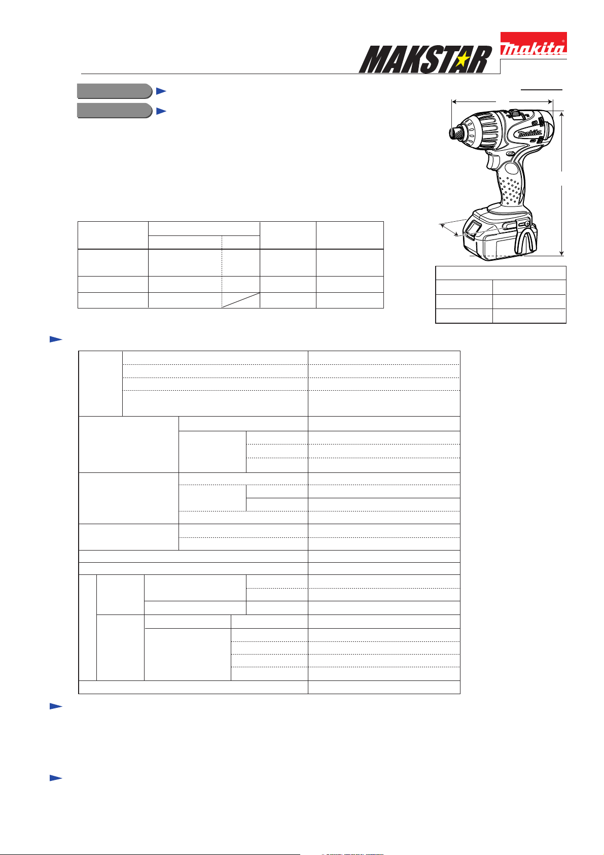
Cordless 4 Mode Impact Driver
CONCEPT AND MAIN APPLICATIONS
Model BTP140 has been developed as the 18V sister tool to Model BTP130.
Uses BL1830, 18V slide-on type Li-ion battery as a power unit,
and features the same high performance and versatility as Model BTP130.
This new product is available in the following variations.
Model No.
BTP140SFE
BTP140*
BTP140RFE BL1830 DC18RA2 Yes
BTP140Z No No No
Specification
Voltage: V 18
Capacity: Ah
Battery
Max. fastening torque:
N.m (in.lbs)
No load speed:
min-1=rpm
Impacts per minute:
min-1=ipm
Torque setting on clutch (screwdriver) mode
Clutch torque range: N.m (in.lbs) 0.5 - 2.0 (4.4 - 17.7)
Capacity
Net weight: kg (lbs) [with BL1830]
Cell
Charging time: min.
Drilling:
mm (")
Fastening
Drill mode
Percussion-drill mode
Screwdriver mode
Impact-driver mode
Battery
type quantity
BL1830 DC18SC
*Model name for USA, Canada, Mexico, Panama
Impact-driver mode
Drill mode
Impact-driver mode 0 - 2,300
Drill mode
Screwdriver mode 0 - 2,300
Impact-driver mode 0 - 3,200
Percussion-drill mode
2 Yes
Small screw M4
Small screw
Standard bolt
High tensile bolt
Coarse-thread
Charger
Soft joint
Hard joint 50 (443)
Lock torque 10 (88.5)
Low
High
Wood 21 (13/16)
Steel
Masonry
Plastic
carrying case
3.0
Li-ion
approx. 45 with DC18SC
approx. 22 with DC18RA
140 (1,240)
10 (88.5)
0 - 700
0 - 2,300
0 - 27,600
16
10 (3/8)
8 (5/16)
M4 - M8
M5 - M14
M5 - M12
22 - 125mm
1.8 (3.9)
W
Dimensions: mm (")
Length (L)
Width (W)
Height (H)
PRODUCT
P 1 /16
L
H
186 (7-3/8)
79 (3-1/8)
246 (9-11/16)
Standard equipment
Belt clip ................................... 1
Plastic carrying case ................ 1
Keyless chuck .......................... 1 (for North American countries only)
Note: The standard equipment for the tool shown above may differ by country.
Optional accessories
Assorted bits, Assorted drill chucks, Adjustable locator, Keyless chuck, Bit piece
Charger DC18SC, Charger DC18RA, Charger DC24SA, Charger DC24SC, Li-ion battery BL1830
Shoulder belt for plastic carrying case
Page 2
P 2 /16
Repair
CAUTION: Remove the saw blade from the machine for safety before repair/ maintenance !
[1] NECESSARY REPAIRING TOOLS
DescriptionCode No. Use for
1R003 Retaining ring pliers for shaft Removing/attaching Retaining ring from/to Shaft
1R045 Gear extractor (large) Disassembling Hammer section
1R212 Tip for retaining ring pliers Modular use with 1R003
1R282 Round bar for arbor 8-50 Modular use with 1R045
1R288 Screwdriver magnetizer Magnetizing screwdriver with which Steel balls are removed.
1R291 Retaining ring S and R pliers Disassembling Bit holder section
1R346 Center attachment for 1R045 Modular use with 1R045
1R351 Anvil holding jig Removing Anvil from Gear case
1R357 Cam A setting jig Assembling Cam A
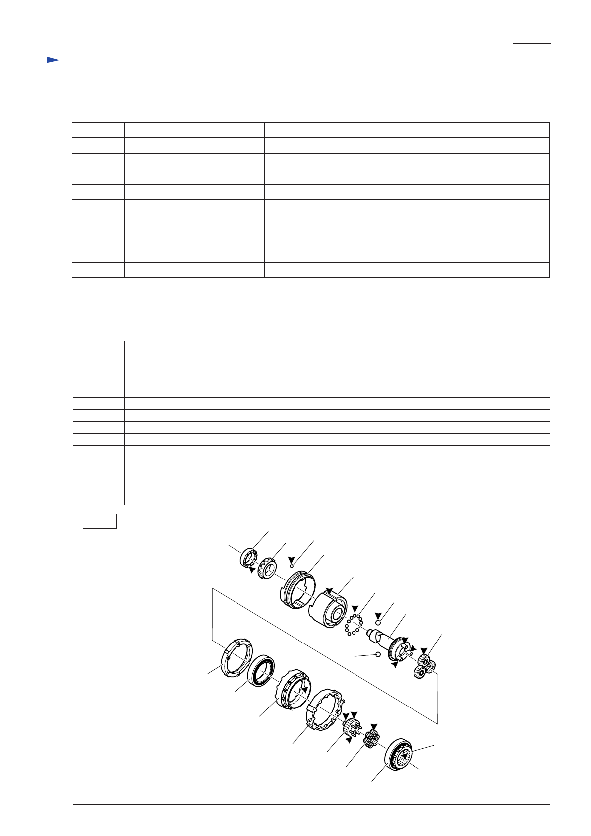
[2] LUBRICATION
Apply Makita grease N. No.2 to the following portions designated with the black triangle to protect
parts and product from unusual abrasion.
Item No. Description Portion to lubricate
40
42
58
59
63
64
68
70
71
72
75
Fig. 1
Cam A Surface that contacts Cam B
Steel ball 3.5 (16 pcs) Whole surface
Hammer Groove that contacts Ring 40
Steel ball 3.5 (23 pcs) Whole surface
Steel ball 5.6 (2 pcs) Whole surface
Spindle complete Three axes for (70) Spur gear 22
Internal gear 50
Spur gear 22 (3 pcs)
Spur gear 7 complete
Spur gear 10 (6 pcs)
Internal gear 38
Inside surface that contacts (70) Spur gear 22
Teeth portion
Teeth portion and six axes for (72) Spur gear 10
Teeth portion
Teeth portion
40
Cam B
42
Ring 40
58
59
63
64
70
Clutch cam
Ball bearing 6805LLB
Clutch change lever
63
68
75
71
72
Ball Bearing 6805LLB
Page 3

P 3 /16
Repair
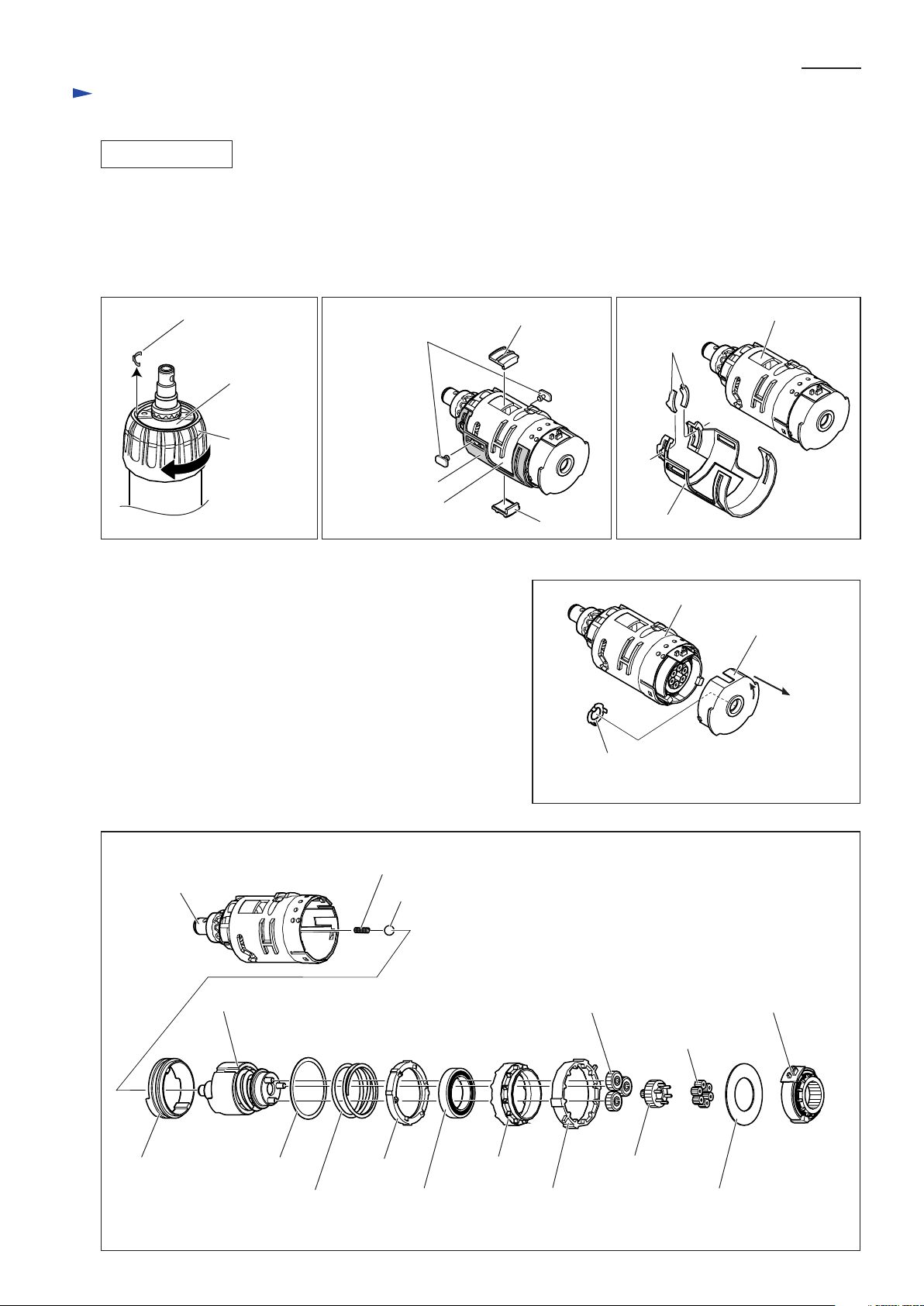
[3] DISASSEMBLY/ASSEMBLY
[3] -1. Impact Assembly
DISASSEMBLING
1) Remove Rear cover by unscrewing two 3x16 Tapping screws and Housing R by unscrewing nine 3x16 Tapping screws.
The machine can now be disassembled as illustrated in Fig. 2.
2) Remove Ring spring 11 from the groove on Anvil. Component parts of Chuck section can now be removed from Anvil.
(Fig. 3)
3) Remove Bumper and two M4x16 Pan head screws. Hammer case can now be removed together with Ball bearing
6802LLB and Retaining ring R-24. (Fig. 4)
Fig. 2
Impact assembly
Housing L
Fig. 3
Chuck section
Compression spring 13
Ring spring 11 Sleeve
Motor section
Steel ball 3.5
groove
Anvil
Tapping screw 3x16 (9 pcs)
Housing R
Rear Cover
Tapping screw 3x16 (2 pcs)
Impact assembly
Anvil
Flat washer 12
Fig. 4
Pan head screw M4x16 (2 pcs)
Bumper
Hammer case Impact assembly
Steel ball 3.5
Two M4 Hex nuts are press-fitted in Gear case of
Impact assembly. Be careful not to get them out
of place when removing the Pan head screws.
Forcing the Pan head screws out of Gear case will
cause the Nuts to fall inside of gear case.
Hex nut M4 Gear case
Page 4
P 4 /16
Repair
[3] -1. Impact Assembly (cont.)
DISASSEMBLING
4) Remove Leaf spring from the space between Gear case and Change ring. Remove Change ring from Gear case
while turning clockwise. (Fig. 5)
5) Remove Pusher U from Gear case, and Pusher L from Change case. Remove two assemblies of Guide and Shoulder
pin-3-6. (Fig. 6)
6) Remove Change case from Gear case. Remove two Plate A's from Change case. (Fig. 7)
Fig. 5 Fig. 6 Fig. 7
Leaf spring
Gear case
Change ring
7) Pull off Motor bracket from Gear case by turning a little bit
counterclockwise. (Fig. 8)
8) Impact assembly can now be disassembled as illustrated in Fig. 9.
assembly of Guide
and Shoulder pin 3-6
Change case
Gear case
Pusher U
Pusher L
Fig. 8
Gear case
Plate A
Change case
Gear case
Motor bracket
Washer 10 comes with Motor bracket
when Motor bracket is removed.
Fig. 9
Ring 40
Anvil
Hammer section
Flat washer 40
Compression Spring 4, removed from Anvil
Steel ball 7.1, removed from Anvil
Spur gear 22 (3pcs)
Clutch cam
Ball bearing 6805LLBCompression spring 41
Internal gear 50
Clutch change lever Flat washer 25
Speed change lever complete
Spur gear 10 (6pcs)
Spur gear 7 complete
Page 5
Repair
[3] -1. Impact Assembly (cont.)
DISASSEMBLING
9) Slide Retaining ring WR-15 a little out of the groove on Anvil using 1R291.
Then remove Retaining ring WR-15 from Anvil using 1R003 to which 2pcs of 1R212 are attached. (Fig. 10)
Note: Retaining ring WR-5 cannot be removed if it is stuck under Cam A.
If so, see Press-fitting Cam A in place on Anvil in page 5.
Fig. 10
Retaining ring WR-15
Retaining ring WR-15
Anvil
1R003
1R212
1R291
P 5 /16
10) Fit the T-shaped end of Anvil in the deep notch in 1R351. (Fig. 11)
11) Remove Anvil from Gear case by pressing down using arbor press. (Fig. 12)
12) The parts around Anvil can now be removed as illustrated in Fig. 13. Two M4 Hex nuts can also removed in this step.
Note: Be careful not to lose small parts such as Steel ball 3.5.
Fig. 11 Fig. 12
Anvil
Anvil
Gear case
T-shaped end
shallow notch
deep notch
1R351
Fig. 13
Arbor press
Anvil
1R351
Gear case
1R351
Cam BCam A
Steel ball 3.5
(16 pcs)
Flat washer 15
Gear case
Ball bearing 6802LLB
Hex nut M4
Anvil
O ring 12.5Nylon washer 15Hammer change lever
Page 6

P 6 /16
Repair
[3] -1. Impact Assembly (cont.)
DISASSEMBLING
Press-fitting Cam A in place on Anvil
Retaining ring WR-5 cannot be removed if it is stuck under Cam A. If so, put off Cam A from Retaining ring WR-5 by
press-fitting Cam A in place using 1R351, 1R357 and arbor press. (Fig. 14)
Fig. 14
1) Fit the T-shaped end of Anvil in the shallow
notches of 1R351.
2) Put 1R357 through Anvil and on Cam A
with the face A on the Cam side.
1R357
face B
face A
Cam A
Gear case
deep notch
face A
face B face A
T-shaped end
of Anvil
shallow notch
face B
3) Press down Cam A using arbor press until it stops
when the face B of 1R357 is flush with the upper end
surface of Anvil.
Arbor press
Anvil
1R357
Retaining ring
WR-15
Cam A
1R351
ASSEMBLING
1) Mount Ball bearing 6802LLB, Nylon washer 15 and two M4 Hex nuts to Gear case. (Fig. 15)
2) Fit O Ring 12.5 in the groove on Anvil, and set the T-shaped end of Anvil in the shallow notch of 1R351. (Fig. 16)
3) Put Gear case through Anvil on 1R351. (Fig. 17)
Fig. 15 Fig. 16
Gear case
Ball bearing 6802LLB
Nylon washer 15
Hex nut M4
O Ring 12.5
Anvil
shallow notch
1R351
Fig. 17
Gear case
Anvil
O Ring 12.5
1R351
Page 7

Repair
[3] -1. Impact Assembly (cont.)
ASSEMBLING
4) Fitting the projection of Hammer in the slit of Gear case,
assemble Hammer change lever to Gear case. (Fig. 18)
5) Put Flat washer 15 through Anvil and into Gear case. (Fig. 19)
6) Put sixteen 3.5 Steel balls in the space between Anvil and
Hammer change lever, and put Cam B through Anvil and on
Hammer change lever. (Fig. 20)
Note: Cam B is not reversible when assembled to Hammer
change lever. Be sure to place as illustrated in Fig. 21.
Fig. 18
Hammer change lever
projection
slit
1R351
P 7 /16
Fig. 19
Flat washer 15
Fig. 20
Cam B
Steel ball 3.5
(16 pcs)
Hammer change lever
When sixteen 3.5 Steel balls are put
in place correctly, there is a space
equivalent to half of the Steel ball.
7) See Fig. 22. Put Cam A through Anvil and on Cam B. Put 1R357 on Cam A with the face B on the Cam side.
Press down Cam A using arbor press until it stops when the face A of 1R357 is flush with the upper end surface of Anvil.
Remove 1R357 from Anvil.
8) Fit Retaining ring WR-15 in the groove on Anvil while expanding Retaining ring WR-15 using 1R291 and 1R003 to
which 2pcs of 1R212 are attached. (Fig. 23)
Fig. 22 Fig. 23
Arbor press
face A
1R357
face B
Fig. 21
Cam B
Correct Wrong
1R212
1R003
face A
face B
1R291
face B face A
Cam A
Anvil
Cam B
Retaining ring WR-15
1R351
Page 8

P 8 /16
Repair
[3] -1. Impact Assembly (cont.)
ASSEMBLING
9) See Fig. 24. Assemble two Plate A's to Change case by sliding in the direction of the black arrows until they stop.
10) Assemble Change case to Gear case by fitting the two projections of Hammer change lever in the space on each side of
Change case. (Fig. 25)
Fig. 24 Fig. 25
Plate A
[A]
[B]
Change case
As illustrated to right, a space is
provided between Plate A and
Change case on each side for
inserting the projection of Hammer
change lever.
11) Hold Gear case with the bit holding side down, and put Ring 40 into Gear case so that the cam portions of Ring 40 is
engaged with the T-shaped end of Anvil. (Fig. 26)
12) Fit Pusher U and Pusher L to Gear case in the openings on Gear case as illustrated in Fig. 27.
Note: Be careful not to confuse Pusher R and Pusher L. A letter "U" is marked on the back of Pusher U while there is
no mark of identification on Pusher L.
Fig. 26
cam positions
Plate A assembled
correctly to Change case
viewed from the side [A]
space
Change case
Plate A
viewed from the side [B]
space
Fig. 27
projections of
Hammer change lever
Plate A
Change case
Pusher U
opening
Gear case
Ring 40
Anvil
13) While pressing Pusher U and Pusher L with fingers, mount two assemblies of Guide pin and Shoulder pin 3-6 to
Ring 40 which is mounted in Gear case in Fig. 25, by inserting the two Shoulder pins into the periphery groove of
Ring 40 through the slits of Gear case and Change case. (Fig. 28)
Fig. 28
You can see the periphery groove
of Ring 40 through the slits of
Gear case and Change case.
periphery groove
T-shaped end of Anvil,
engaged with Ring 40
opening
Pusher L
Pusher U
H-shaped projections
assembly of Guide
and Shoulder pin 3-6
Gear case
Ring 40
assembly of Guide
and Shoulder pin 3-6
Change case
Pusher L
Page 9

P 9 /16
Repair
[3] -1. Impact Assembly (cont.)
ASSEMBLING
14) While pressing Pusher U and Pusher L with fingers, fit the female threads on the inside of Change ring to the male
threads on Pusher U and Pusher L. Turn Change ring counterclockwise until it stops. (Fig. 29)
Note: If Change ring cannot be turned, check whether or not the Pushers are correctly mounted as illustrated in Fig. 28
on page 7.
15) Put Leaf spring in place between Gear case and Change ring. (Fig. 30)
Fig. 29 Fig. 30
Change ring
female threads
male threads
Gear case
Pusher L
16) Assemble Ball bearing 6802LLB and Retaining ring R-24 to Hammer case, and secure Hammer case to gear case with
two M4x16 Pan head screws. Put Compression spring 4, then Steel ball 7.1 into the hole of Spindle. (Fig. 31)
Note: Be careful not to get two M4 Hex nuts out of place when tightening the Pan head screws. (Fig. 4 in page 2)
17) Grasping the pins on Spindle complete with pliers, assemble Hammer section to Gear case with the raised portions
fitting in the groove on Hammer. (Fig. 32)
Fig. 31 Fig. 32
Pan head screw M4x16 (2 pcs)
Anvil
Pusher U
Steel ball 7.1
Leaf spring
raised portions groove on Hammer
Change ring
Gear case
pin on Spindle complete
Hammer case
18) Put Flat washer 40 and Compression spring 41 into Gear case. Then insert Clutch cam with the six raised portions on
the Clutch cam's periphery fitting in the corresponding grooves on the inside surface of Gear case.
Put Internal gear 50 into Gear case. (Fig. 33)
Note: Clutch cam is not reversible when assembled to Gear case. Be sure to place so that the cam side faces towards
Internal gear 50. (Fig. 33)
19) Assemble Clutch change lever to Gear case as illustrated in Fig. 34.
Fig. 33 Fig. 34
Flat washer 40
raised portions
There are six
projections on
the cam side.
raised portions
Compression spring 4
Compression spring 41
Clutch cam
Internal gear 50
Ring 40 Hammer section
Clutch change lever
Change case
Slide the two projections on Clutch change lever
along the slits on gear case until they stops.
Then put them through the slits on Change case.
pliers
projections
Page 10

Repair
[3] -1. Impact Assembly (cont.)
ASSEMBLING
20) See Fig. 35.
Put three 22 Spur gears through the pins on Spindle complete. Put Flat washer 25 on Internal gear 50.
Engage Spur gear 7 complete with three 22 Spur gears.
Mount Speed change ring complete to Gear case.
Put six 10 Spur gears through the six pins on Spur gear 7 complete.
Note: Be sure that every gear is engaged with adjacent gear(s).
Fig. 35
Flat washer 25Gear case
P 10 /16
Spur gear 22
(3 pcs)
21) Insert the notch on Motor bracket through the projection on Gear case until Motor bracket is set a little bit apart from
Gear case. (Fig. 36)
22) By turning Motor bracket, fit the projection on Motor bracket to the groove on gear case. Insert Motor bracket into
Gear case until it stops. Then secure Motor bracket to Gear case by turning clockwise. (Fig. 37)
Fig. 36 Fig. 37
projection notch
Spur gear 7 complete
*includes Ball bearing 6805LLB and Internal gear 38
groove
*Speed change
ring complete
Gear case
projection
Spur gear 10
(6 pcs)
Speed change ring complete
Motor bracket
Page 11

P 11 /16
Repair
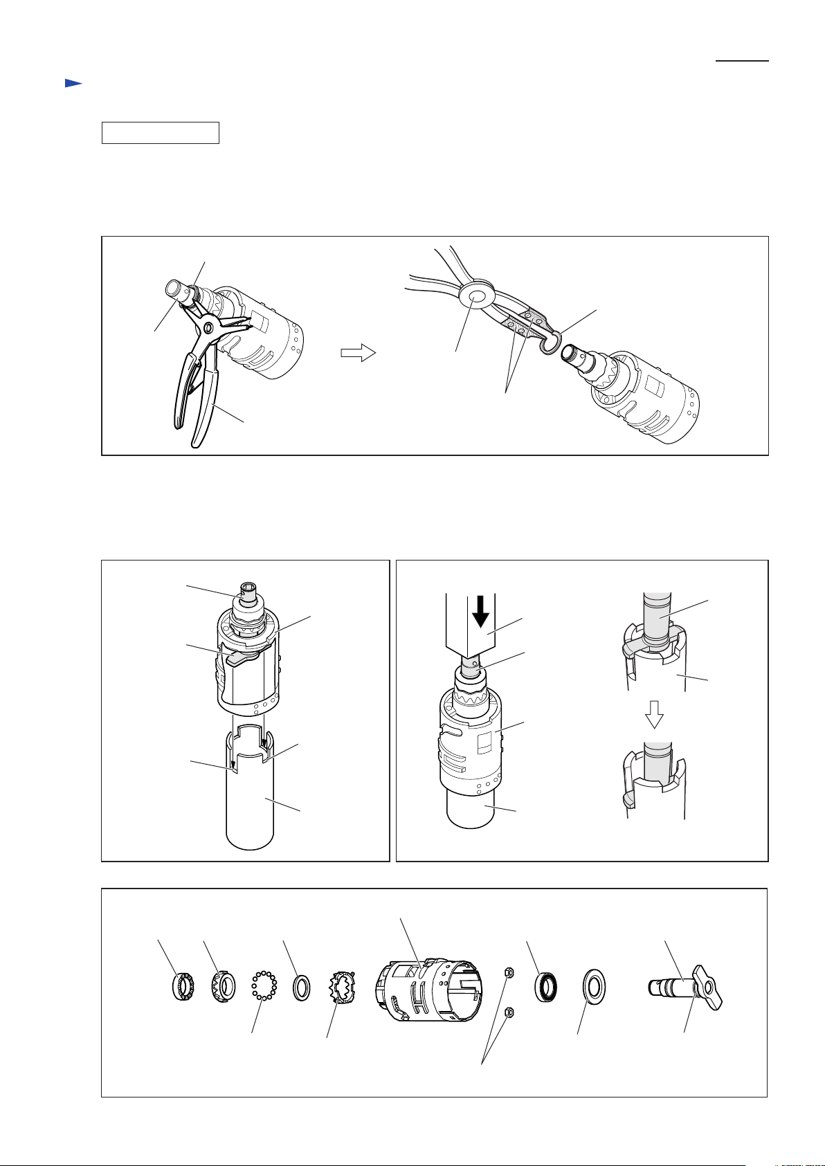
[3] -2. Hammer Section
DISASSEMBLING
1) Take out Hammer section from the machine. (See Figs. 2 to 9.)
2) Install the following repair tools on Hammer section as illustrated in Fig. 38: 1R045; 1R346; 1R282
3) Hold Hammer section as illustrated in Fig. 39. Press down Hammer to the full by turning the handle of 1R045 in the
direction of the black arrow. Then adjust the opening for Steel ball insertion to the top of cam groove on Spindle by
turning the handle in the opposite direction. Two 5.6 Steel balls can now be removed from Spindle using tweezers or
a slotted screwdriver magnetized with 1R288.
4) Hold Hammer section as illustrated in Fig. 38, and release 1R045 from Hammer section by turning the handle.
Caution: Do not hold gear extractor as illustrated in Fig. 39 when releasing the Hammer section.
Failure to follow this instruction could cause most of twenty-four 3.5 steel balls to fall out of Hammer.
Fig. 38 Fig. 39
tighten
Spindle
loosen
1R045
top of cam groove
on Spindle
1R346
1R282
5) Remove Spindle complete, Cup washer 24 and Compression spring 24 from Hammer. (Fig. 40)
6) Remove Flat washer 24 and twenty-three 3.5 Steel balls from Hammer. (Fig. 41)
Fig. 40 Fig. 41
opening for Steel
ball insertion
Steel ball 5.6
Hammer
Compression
spring 24
Hammer
ASSEMBLING
Do the reverse of the disassembling steps.
(Refer to Figs. 41, 40, 39.)
Note: Make sure that twenty-three 3.5 Steel balls
are prepared before mounting. (Fig. 42)
Spindle complete
Cup washer 24
Fig. 42
There is a space equivalent to two 3.5 Steel balls in Hammer
when twenty-three 3.5 Steel balls are correctly mounted.
Steel ball 3.5: 23 pcs
Hammer
Steel ball 3.5 (23 pcs)
Flat washer 24
Hammer
Page 12

Repair
[3] -3. Motor Section
DISASSEMBLING
1) Take out Motor section by disassembling the the product
as illustrated in Fig. 2 on page 2.
2) Shift the tail of Torsion spring from Carbon brush onto the
notch on Brush holder to remove the suppressing force of
Torsion spring. And disconnect Carbon brush from
Commutator by pulling them off halfway. (Fig. 43)
It is not necessary to remove Carbon brush completely.
3) Separate Armature-Yoke unit assembly from Brush holder
complete. (Fig. 44)
4) Remove Armature from Yoke unit. (Fig. 45)
Fig. 44 Fig. 45
P 12 /16
Fig. 43
Carbon brush
Torsion spring
put on the notch
of Brush holder
Yoke unit Armature
Brush holder complete
ASSEMBLING
1) Assemble Motor section.
Note 1:
Yoke unit is not reversible when assembled to Armature. Be sure to assemble with the notch of Yoke unit on the
drive-end of Armature. (Fig. 46) If assembled wrong, Motor section could not be assembled to Housing (L).
Note 2:
Yoke unit is a strong magnet. When assembling Armature to Yoke unit, be sure to hold the commutator portion
as illustrated to left in Fig. 47. If you hold the Armature core as illustrated to right, your fingers could be pinched
between Yoke unit and the fan of Armature that is pulled strongly by the magnet force.
Fig. 46
Fig. 47
Put Armature-Yoke unit assembly
as illustrated below.
Yoke unit
Pull down Yoke unit
towards the work bench.
Notch
[Wrong][Correct] [Wrong][Correct]
Your fingers could be
pinched and injured.
Page 13

Repair
[3] -3. Motor Section (cont.)
ASSEMBLING
2) Assemble Armature-Yoke unit assembly to Brush holder complete as illustrated in Fig. 48.
3) Assemble Motor section to Impact assembly. (Fig. 49)
Note: Make sure that the gear on Armature is engaged with six 10 Spur gears in Impact assembly.
4) Slide Plate C of Mode change lever assembly towards Lever until it stops. (Fig. 50)
Fig. 48 Fig. 50Fig. 49
P 13 /16
Yoke unit
Armature
Brush holder
complete
5) Set Impact assembly to drill mode by turning Change case as illustrated in Fig. 51.
Note: Be careful not to put the projection of Clutch change lever out of the slit of
Change case when turning Change case.
6) Assemble Mode change lever assembly (including Plate B and Plate C) to Impact assembly as illustrated in Fig. 52.
Fig. 51
projection of
Clutch change lever
Change case
gear on Armature shaft
Impact assembly
Motor section
Lever
Plate C
Mode change
lever assembly
Clutch change lever
in Drill mode
Fig. 52
[Speed change ring complete]
two small bosses
Gear case
ends of Change case
space B
space A
one large boss
Motor bracket
Fit the width A of Mode change lever to the space A on gear case.
width A: from rib A1 to rib A2
space A: between the ends of Gear case
Put rib B in the space B on Speed change ring complete.
space B: between the two small bosses and one large boss
[Mode change lever assembly]
(viewed from top)
rib A1
rib B
Mode change lever*
width A
rib A2
Plate B
Plate C
*The portions drawn in broken lines
are positioned on the back of plate C.
Page 14

Repair
[3] -4. Switch Section
P 14 /16
ASSEMBLING
Mount F/R Change lever to Switch by fitting the prong
portion of F/R Change lever to the boss on Switch as
illustrated in Fig. 53., and assemble them to Housing L.
Fig. 53
prong portion
F/R Change lever
boss
Switch
[3] -6. Inner Section (Motor Section and Impact Assembly)
ASSEMBLING
1) While holding Mode change lever assembly so that
it does not fall off Gear case, mount Inner Section
(Motor section and Impact assembly) to Housing L
by fitting the notch of Yoke unit to the projection of
Housing L. (Fig. 54)
2) See Fig. 55.
After installation of Inner section, make sure that;
A) The flat portion of Brush holder complete is at
90 degrees to the surface of Housing L.
B) Yoke unit is put in four ribs on Housing L.
C) The top of the projection of Gear case faces
towards Switch.
Fig. 54
notch of Yoke unit
Mode change lever assembly
Yoke unit
Fig. 55
Brush holder complete viewed from rear
flat portion of
Brush holder complete
edge surface of
Housing L
90 degrees
projection
Housing L
A) Brush holder complete
B) ribs to hold Yoke unit
Yoke
unit
Gear case
Housing L
Brush holder complete
Switch
B) ribs to hold Yoke unit
C) projection of Gear case
Page 15

Circuit diagram
Fig. 56
Color index of lead wires' sheath
Black
Red
Orange
Blue
P 15 /16
Brush holder complete
LED Job light
Connector
Switch
Light
circuit
Terminal
Page 16

Wiring diagram
Fig. 57
Wiring of Lead Wires of Light Circuit
P 16 /16
Lead wires (red, black)
of Light circuit
Lead wire holder
pin
boss
rib for holding Impact assembly
LED
Light circuit
Terminal
*The Lead wires (red, black) of Light circuit
must be tight in the circled area.
*Be careful not to route Lead wires (red, black)
on the rib for holding Impact assembly.
Do not cross the Lead wires (red, black)
in the circled area.
Fix the Lead wires (red, black) with these
Lead wire holders, and route between the pin
and the boss.
Put Light circuit in place
so that the orange Lead wire
faces towards the Terminal side.
Switch side
Lead wire
(orange)
Terminal side
Wiring of Lead Wires of Switch and Brush Holder Complete
Assemble each Connecting terminal
to Switch at approx. 20
vertical.
approx. 20
Connector
With these Lead wire holders,
fix the Lead wires connected
to each Connector.
Put the following lead wires between the rib
and Light circuit.
*Lead wires (red, black) from Terminal
to Connector
*Lead wire (blue) from Switch to Connector
degrees
degrees to the
Brush holder complete
Lead wire holder
Connector
Lead wire holder
Switch
Be careful not to route
the lead wires on the
wall of Housing L in the
circled area.
Light circuit
rib
 Loading...