

Makita BSS500Z, BSS500, BSS500RFE, BSS500RF, BSS501Z Technical Information
...
T
ECHNICAL INFORMATION
Model No.
Description
BSS500, BSS501
Cordless Circular Saw 136mm (5-3/8")
CONCEPT AND MAIN APPLICATIONS
Models BSS500 and BSS501 have been added to the lineup of
MAKSTAR Cordless Circular Saw, featuring compact and
lightweight design for high maneuverability and easy handling.
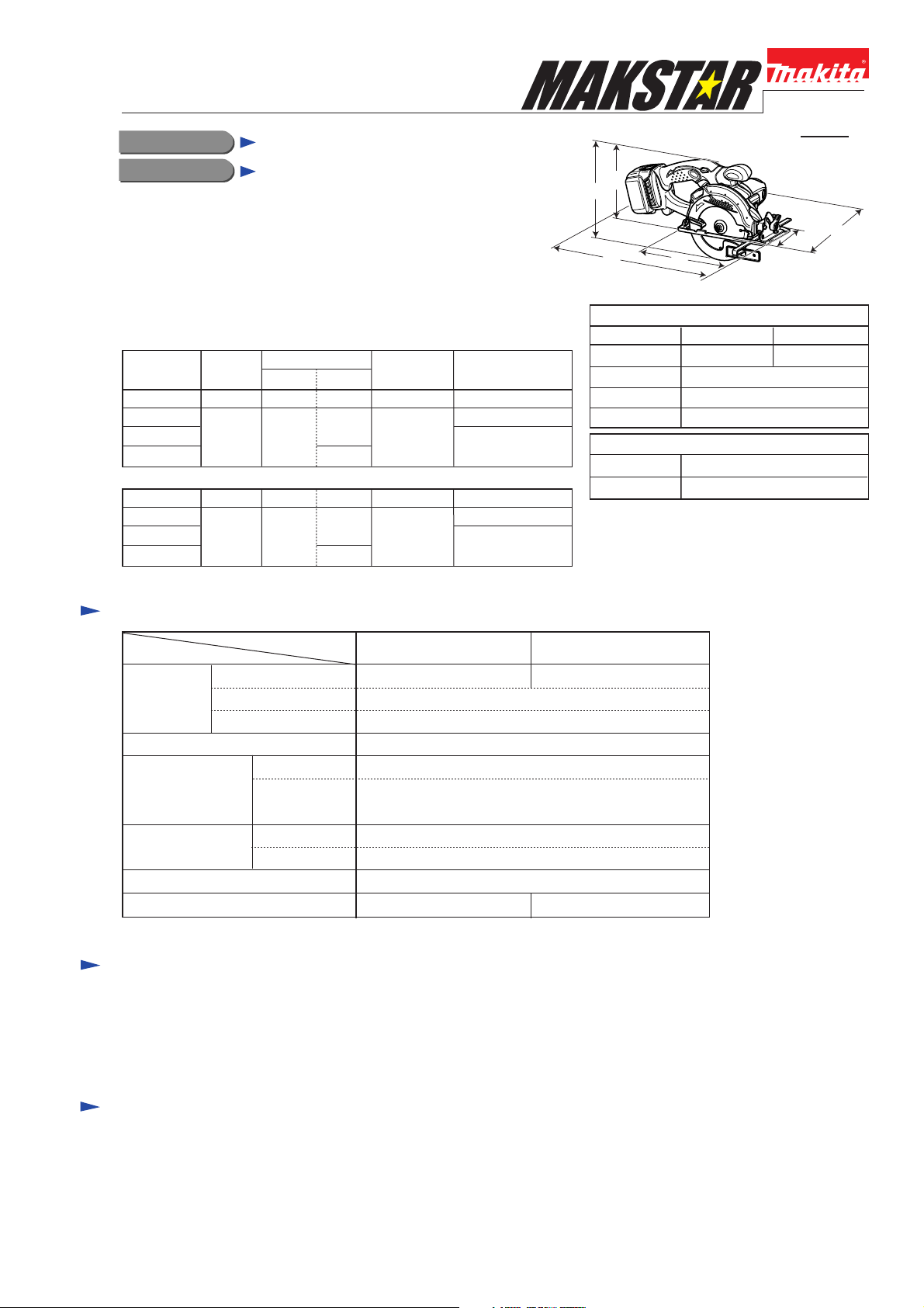
PRODUCT
P 1 /14
H2
H1
W1
W2
L1
(The image illustrated above is Model BSS500.)
L2
These products are available in the following variations.
BSS500
Model No.
BSS500Z
BSS500
BSS500RFE
BSS500RF
BSS501
BSS501Z
BSS501
BSS501RFE
BSS501RF
The items listed below in "Standard Equipment" also come with the above items.
Charger
Battery
type quantity
No No
BL1430DC18RA
No No No All countries
BL1830DC18RA
No
2
1
No
2
1
Plastic
carrying case
No All countries
North America
Yes
Yes
All countries except
North America
North America
All countries except
North America
Offered to
Specification
Specifications
Voltage: V
Battery
No load speed: rpm= min.-1
Size of blade:
mm (")
Max. cutting
capacities: mm (")
Electric brake
Net weight: kg (lbs)
*with Battery BL1430 **with Battery BL1830
Capacity: Ah
Cell
Diameter
Hole diameter
at 0
at 45 degrees
Model
degree
3.0
Li-ion
3,600
136 (5-3/8)
North American countries: 15.88 (5/8)
Other countries: 20 (13/16)
51 (2)
35 (1-3/8)
Yes
2.5 (5.5)* 2.6 (5.7)**
Length (L1)
Width (W1)
Height (H1)
Height (H2)
Length (L2)
Width (W2)
BSS501BSS500
1814.4
Dimensions: mm (")
BSS500 BSS501
359 (14-1/8) 364 (14-3/8)
183 (7-1/4)
201 (7-7/8)
145 (5-3/4)
Base Size: mm (")
213 (8-3/8)
109 (4-1/4)
Standard equipment
TCT Saw blade 136mm, 16T ............................ 1
Hex wrench 5 ..................................................... 1
Guide rule .......................................................... 1
Dust nozzle (for European countries only) ....... 1
Note: The standard equipment for the tool shown above may differ by country.
Optional accessories
Fast charger DC18RA
Charger DC18SC
Charger DC24SA (for North America only)
Charger DC24SC (for all countries except North America)
Li-ion battery BL1430 (for BSS500)
Li-ion battery BL1830 (for BSS501)
TCT Saw blade for wood 136mm, 16T
Dust nozzle
Repair
CAUTION: Remove the battery, SAW BLADE from the machine for safety
before repair/ maintenance !
[1] NECESSARY REPAIRING TOOLS
Code No. Description Use for
1R003
1R027
1R028
1R031
1R032
1R037
1R263
1R269
1R278 Round bar for arbor 4-50
1R281 Round bar for arbor 7-50
1R291
1R356 Bearing plate 10mm (for arbor press)
1R212 Tip for Retaining ring pliers
Retaining Ring S Pliers ST-2N
Bearing setting pipe 18-10.2
Bearing setting pipe 20-12.2
Bearing setting pipe 28-20.2
Bearing setting plate 8.2
Bearing setting plate 20.2
Bearing extractor (2 pcs)
Bearing extractor
Retaining ring S and R pliers Removing/installing Retaining ring
Wrench for bearing retainer1R316
90 degree set square1R208
Removing Retaining ring WR-26
Assembling Ball bearing 6900ZZ and Helical gear 15 to Gear shaft
Assembling Helical gear 35 to Gear shaft
Supporting Bearing box section when removing Helical gear 23,
Sleeve 10, and Ball bearing 6900ZZ from Spindle
Supporting Gear shaft when assembling Helical gear 35,
Ball bearing 6900ZZ and Helical gear 15 to Gear shaft
Removing Helical gear 35, Ball bearing 6900ZZ and Helical gear 15
from Gear shaft
Removing Bearing box section
Removing Ball bearing 604ZZ and 696ZZ
Removing Ball bearing 604ZZ
Removing Helical gear 15 and Ball bearing 6900ZZ
Removing/installing Bearing retainer 14-23
Removing Ball bearing 604ZZ
adjustment for accuracy of 90 degree/45 degree cut
Removing Retaining ring WR-26
P 2 /14
[2] LUBRICATION
Apply the following grease to protect parts and product from unusual abrasion:
Makita grease N. No.2 to the following portions designated with the black triangle
Machine oil to the following portions designated with the gray triangle
Item No.
19
51
Fig. 1
Description
Handle R
Thickness ring
Helical gear 23
3g to the gear room for Helical gear 23 and Helical gear 15
3g to the gear room located on the opposite side for Helical gear 35
and Pinion gear of Armature shaft
Surface that contacts Safety cover complete
Portion to lubricate Lubricant
19
(viewed from the opposite side)
19
Helical gear 15
Helical gear 35
Safety cover complete
51
Repair
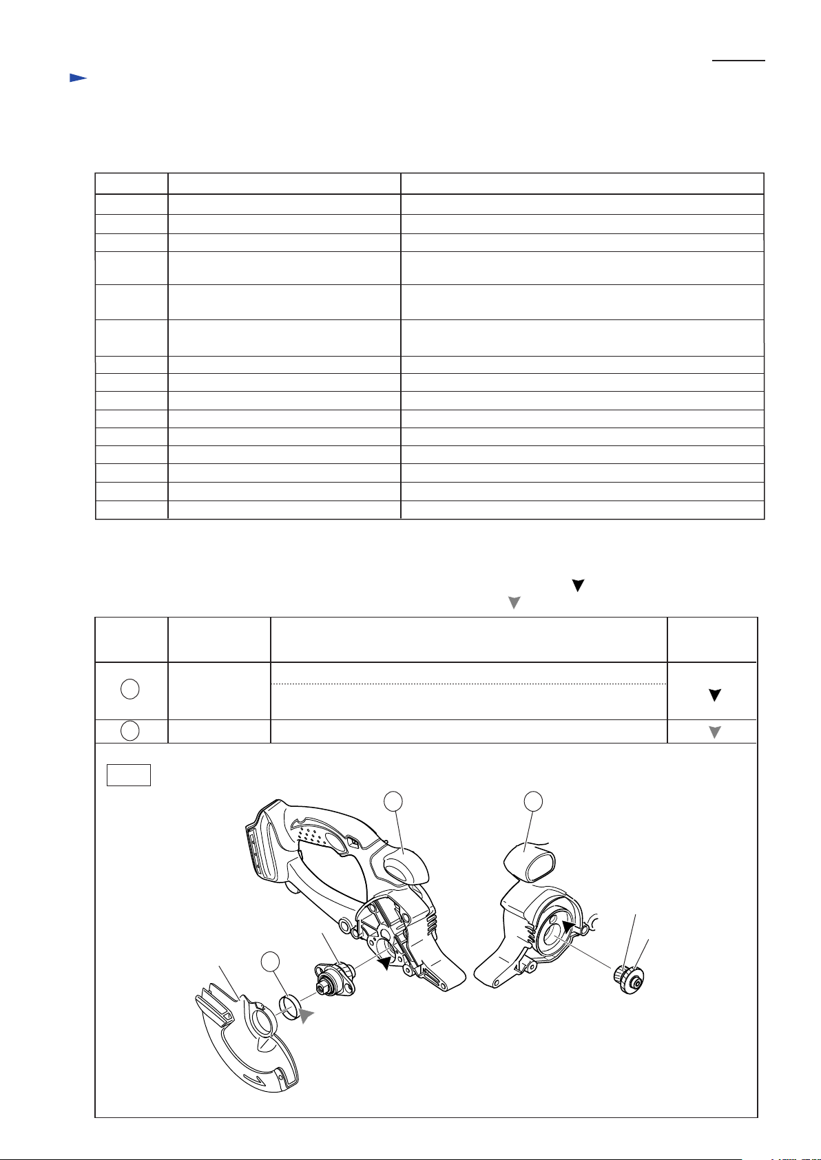
[3] DISASSEMBLY/ASSEMBLY
[3] -1. Base
DISASSEMBLING
Base is joined to Motor section and Saw section with the following screws and nuts:
*at Hinge portion: Pan head screw M5, Hex lock nut M5-8
*at Depth guide portion: Flat head square neck bolt M6x75, Hex nut M6
Remove them in the order of Fig. 2, 3, 4.
Fig. 2
Turn Safety cover in the direction of the arrow
to obtain enough space for you to remove
Rubber sleeve 6.
Keeping Safety cover in the position,
remove Sleeve 4 and Rubber sleeve 6 from Blade case
by unscrewing Tapping screw 4x25.
Safety cover
Rubber sleeve 6
Sleeve 4
Tapping screw 4x25
P 3 /14
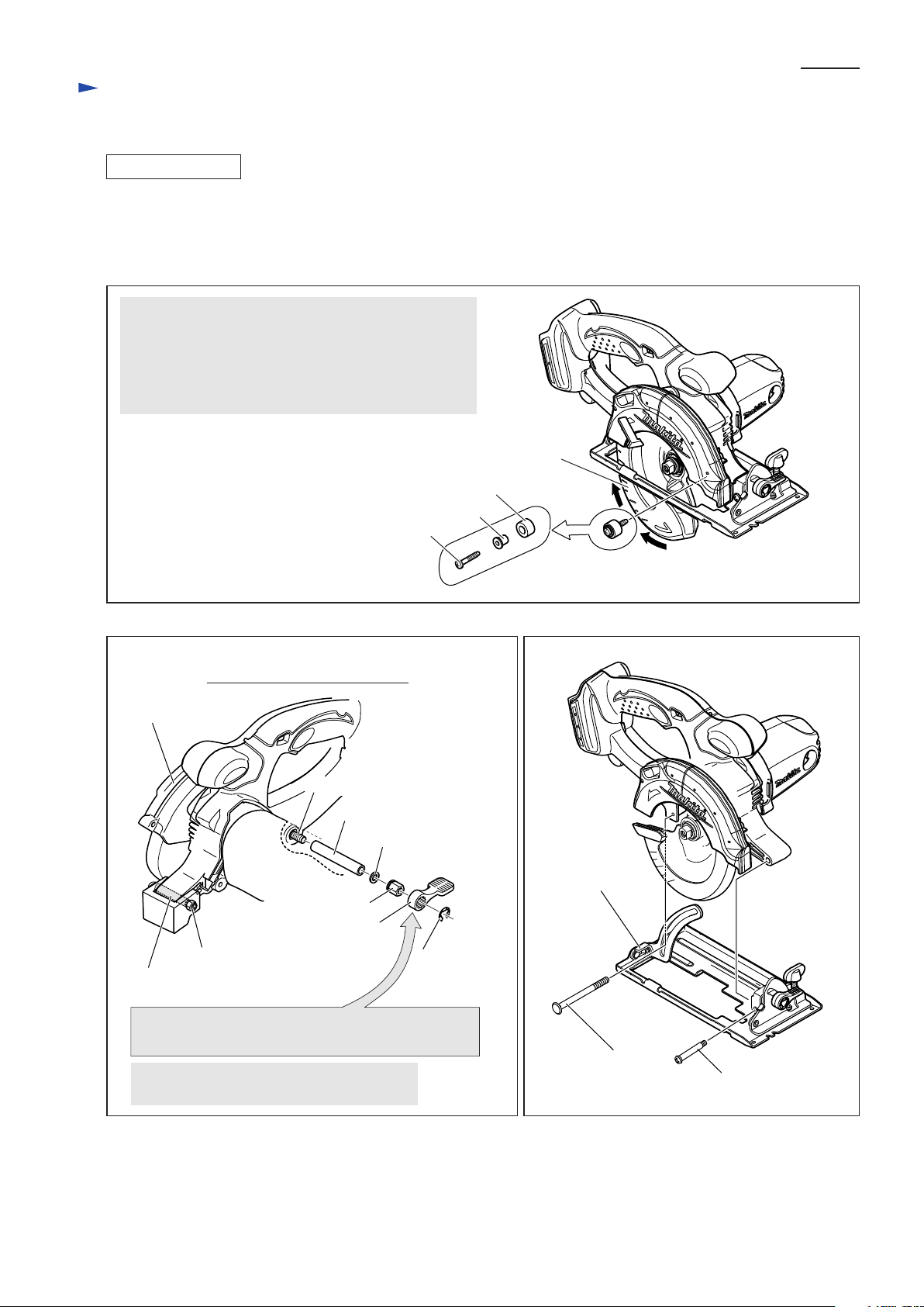
Fig. 3
Handle and Motor housing
viewed from Motor housing side
Safety cover
Flat head square neck bolt M6x75
Pipe 6
Flat washer 6
Hex nut M6
Lever 40
Hex lock nut M5-8
Pan head screw M5
For easy removal of Hex nut M6, loosen Hex nut M6
using Lever 40 as a wrench before removing Lever 40.
Remove Hex lock nut M5-8 from Pan head
screw M5.
Stop ring E-8
Fig. 4
Base
Flat head square
neck bolt M6x75
Pan head screw M5
Repair
[3] DISASSEMBLY/ASSEMBLY
[3] -1. Base (cont.)
ASSEMBLING
1) Do the Reverse of the disassembling Steps.
2) After assembling Base to the machine, adjust the following portion for smooth adjustment of cut depth.
A. Pan head screw M5 in the Hinge portion of Base
Must be tightened so that the Machine can move along
Depth guide smoothly without rattling. (Fig. 3 and 4)
B. Lever 40
Must be installed so that it can be locked at an angle of
between 0 and 30 degrees from the Centerline towards
Switch side when the Cut depth is set to the Maximum.
(Fig. 5)
Also do Adjustment for Accuracy of 90 degree and
45 degree Cut. (See page 11 for details.)
Fig. 5
Base
Depth guide
30 degrees
Center line of Handle
Lever 40
P 4 /14
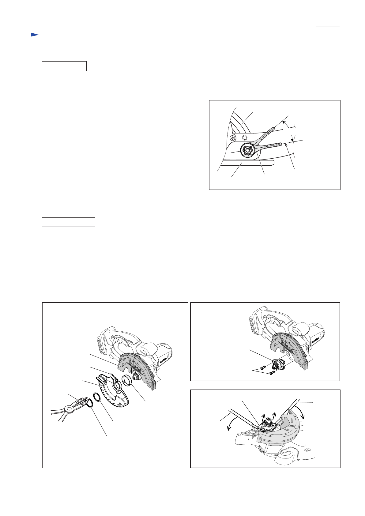
[3] -2. Safety Cover Complete and Bearing Box Section
DISASSEMBLING
1) Remove Rubber sleeve. (Fig. 2)
2) By removing Retaining ring WR-26 with 1R212, the following parts can be removed (Fig. 6):
Flat washer 26, Safety cover, Tension spring 4, Thickness ring.
Note : Safety cover complete can be separated from Blade case by unhooking the end of Tension spring 4 from
Blade case.
3) By unscrewing two M5x16 Countersunk head screws, Bearing box section can be removed by hand. (Fig. 7)
If cannot be removed by hand, lever off using a pair of 1R263 as illustrated in Fig. 7A.
Note: It is recommended to use cordless impact driver for removing the screws because threadlocker is
applied to them.
Fig. 6
Blade case
Tension spring 4
Safety cover
1R212
Thickness ring
Fig. 7
Bearing box
Countersunk head
screw M5x16
Fig. 7A
Bearing box section
1R263
Flat washer 26
Retaining ring WR-26
1R263
Repair
[3] DISASSEMBLY/ASSEMBLY
[3] -2. Safety Cover Complete and Bearing Box Section (cont.)
DISASSEMBLING
P 5 /14
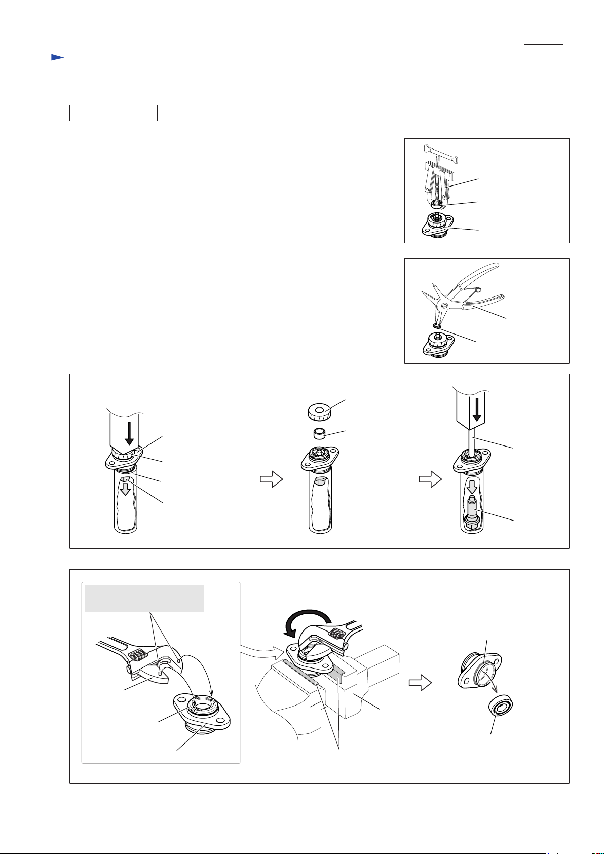
4) Remove Ball bearing 696ZZ from Bearing box section with 1R269. (Fig. 8)
5) Remove Retaining ring S-10 with 1R291. (Fig. 9)
6) Remove Spindle by doing the steps below (Fig. 10):
1. Put Bearing box section on 1R031 with Helical gear 23 side up.
2. Remove Helical gear 23 and Sleeve 10 by pressing the end face of
Spindle using arbor press.
3. Apply 1R281 to the end face of Spindle, and press it using arbor press.
Spindle can now be removed from Bearing box section.
Important: Ball bearing 6900DDW in Bearing box section will always
be damaged in these steps.
Do not forget to replace with new one.
7) Attach a pair of 1R041 to vise. Fix Bearing box section in vise.
Remove Bearing retainer 14-23 from Bearing box by turning counter clockwise with 1R316. Damaged Ball bearing 6900DDW can now be
removed. (Fig. 11)
Fig. 10
Helical gear 23
Fig. 8
1R269
Ball bearing 696ZZ
Bearing box section
Fig. 9
1R291
Retaining ring S-10
Fig. 11
Fit these pins in the groove
of Bearing retainer 14-23.
1R316
Bearing retainer
14-23
Bearing box
Bearing box section
Helical gear 23
1R031
Spindle
1R041
Sleeve 10
1R281
Spindle
O ring 26
Vise
Ball bearing 6900DDW,
damaged in the previous step
 Loading...