

Page 1
T
Models No.
ECHNICAL INFORMATION
BPT351 (LXTP01*1)
PRODUCT
P 1/ 15
Description
Cordless Pin Nailer
*1 Model number for North and Central American countries
CONCEPT AND MAIN APPLICATIONS
Model BPT351 has been developed as a 18V Cordless Pin Nailer
with more working capacity than that of 14.4V Model BPT350.
Its features and benefits are the same as BPT350
except for 18V Li-ion battery.
This model is available in the following variations.
Model No.
BPT351RFE
(LXTP01)
BPT351RFX No
BPT351Z
(LXTP01Z)
BPT351ZX
All models also include the accessories listed below in "Standard equipment".
Charger
DC18RA
No No No No
Battery
Type Quantity
BL1830 2
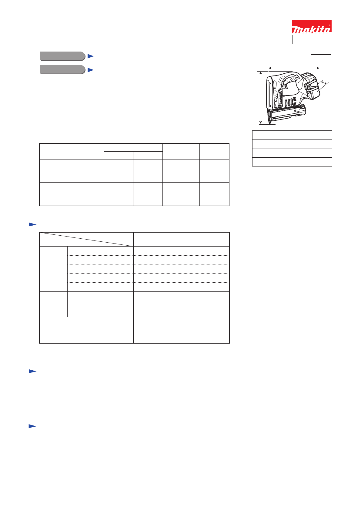
Specification
Specifications
Voltage: V 18
Battery
Pin nails
(23Ga)
Magazine capacity: pcs.
Weight according to
EPTA-Procedure 01/2003: kg (lbs)
*2 with battery BL1815
*3 with battery BL1830
Length: mm (")
Diameter: mm (") 0.6 (1/32)
Model No.
(11/16, 1, 1-3/16, 1-3/8)
1.9*
Plastic
carrying case
Yes
BPT351 (LXTP01)
1.3/ 3.0Capacity: Ah
24/ 54Energy capacity: Wh
Li-ionCell
22 with DC18RACharging time: min.
18, 25, 30, 35
130
2/ 2.1*3 (4.2*2/ 4.6*3)
Systainer
case
No
Yes
No
Yes
H
Dimensions: mm (")
Length (L)
Width (W)
Height (H)
L
W
249 (9-3/4)
79 (3-1/8)
227 (8-15/16)
Standard equipment
Safety goggles ......................... 1
Nose adapter ............................ 1
Hex wrench 3 .......................... 1
Belt clip ................................... 1
Note: The standard equipment for the tool shown above may vary by country.
Optional accessories
Pin nails; 18mm (11/16"), 25mm (1"), 30mm (1-3/16"), 35mm (1-3/8")
Fast Charger DC18RA
Li-ion Battery BL1815
Li-ion Battery BL1830
Page 2
P 2/ 15
Repair
CAUTION: Repair the machine in accordance with “Instruction manual” or “Safety instructions”.
[1] NECESSARY REPAIRING TOOLS
DescriptionCode No. Use for
783201-2
1R220 Ratchet head 9.5
1R222 Socket adapter
1R228
1R254 Torque wrench shaft 2-6N.m
134873-0 Bit adapter
1R266 Spring pin extractor M2
1R268
[2] LUBRICANT AND ADHESIVE APPLICATION
Apply the following lubricants to protect parts and product from unusual abrasion.
Apply the following adhesive.
Item No. Description Portion to lubricate Lubricant
11
59 DC motor Pinion gear
61 Internal gear 69 Teeth that engages with Spur gear 27
64
66 Spur gear 55 complete
67 Plane bearing 10 Inside surface that contacts 64 Spur gear 7 complete
89 Cam block Portion that contacts 66 Spur gear 55 complete
Hex. wrench 3 (standard equipment)
1/4" Hex. shank bit for M4
Spring pin extractor M3
screwing / unscrewing Hex socket head bolt and M3x4 Pan head screw
disassembling magazine section
LUBRICANT
Rail Grooves of both sides where Hammer slides
Guide bolt Shaft surface except thread portion13
Spur gear 7 complete
Teeth that engages with the lower gear
of 66 Spur gear 55 complete
Teeth
Pin and cam portions
Amount
Molybdenum disulfide
lubricant
a little
Makita grease N No.2
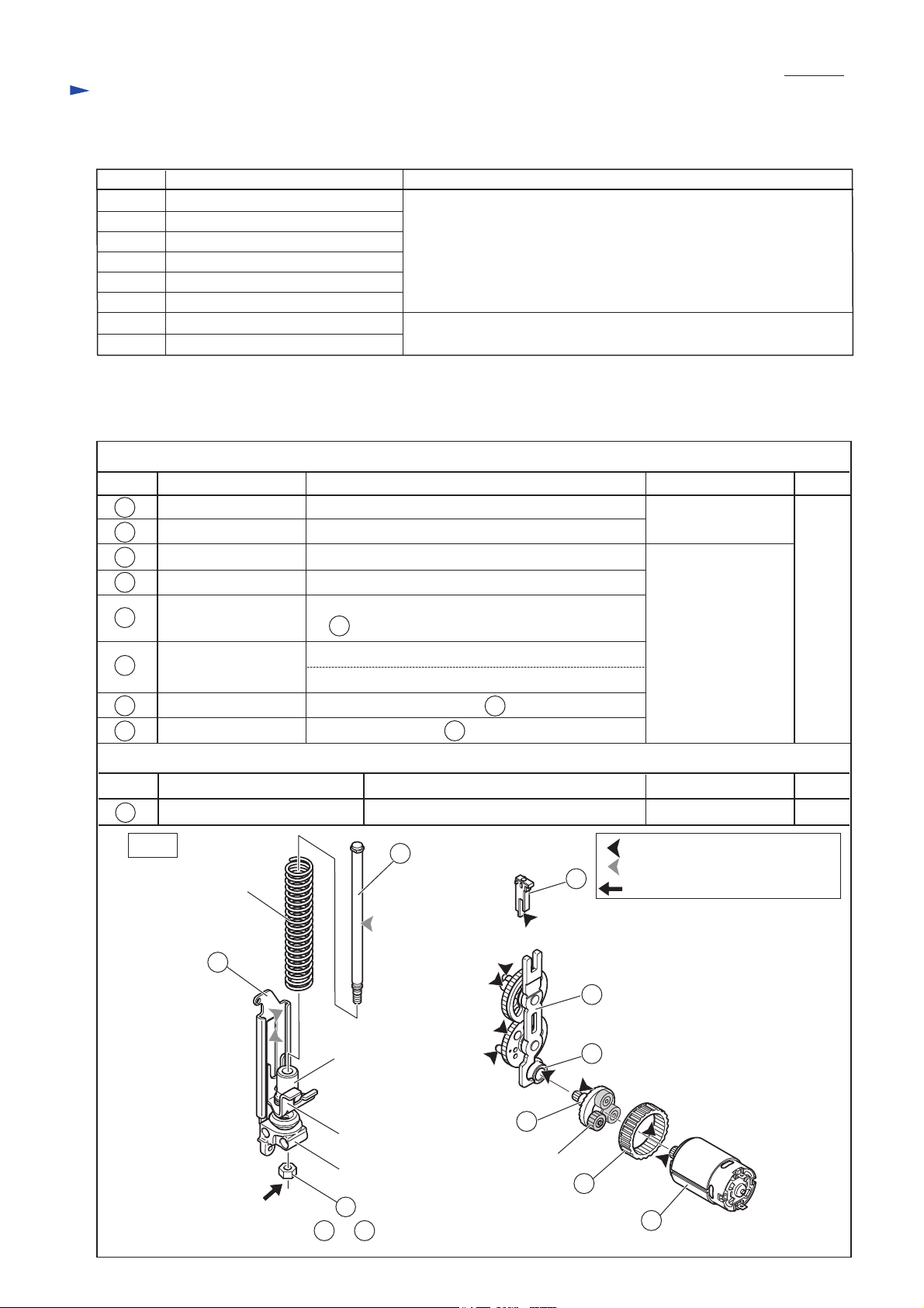
Item No. Description
34
Compression spring 17
M6 Hex nut
Fig. 1
11
Screw to with Loctite 272 put on the thread.
Thread
Spring holder
Hammer
Holder
34
13
34
ADHESIVE
Portion to apply adhesive
13
64
Spur gear 27
(3pcs.)
89
61
Adhesive
: Makita grease N No.2
: Molybdenum disulfide lubricant
: Loctite 272
66
67
59
Amount
a littleLoctite 272
Page 3

Repair
[3] DISASSEMBLY/ASSEMBLY
[3] -1. Replacing Driver
(1) Remove four Bind PT3x16 Tapping screws and Front cover. (Fig. 2)
(2) Remove Upper plate as drawn in Fig. 3.
(3) Remove Pin 4 for connecting Driver and Hammer. (Fig. 4)
(4) Remove Driver as drawn in Fig. 5.
Fig. 2 Fig. 3 Fig. 4 Fig. 5
Front cover
Bind PT3x16
Tapping screw
(4pcs.)
Slide Upper plate
upward.
Slide Driver upward.
Hammer
Pin 4
Driver
P 3/ 15
Note: A few of pin nails often remain in the tool, and if so, it is impossible to insert Driver into Driver guide.
(5) Remove two M4x6 Hex socket head bolts and Driver guide cover. Remove the jammed pin nails. (Fig. 6)
(6) Slide the new Driver into the groove of Driver guide. (Fig. 7)
Note: If M4x10 Hex socket head bolt(s) are loosened, the stroke of Driver guide may tilt.
In that case, slide Driver into the groove of Driver guide before securing M4x10 Hex socket head bolt(s),
and then secure M4x10 Hex socket head bolt(s).
(7) Insert Pin 4 for connecting Driver and Hammer.
(8) Set Driver guide cover in place with two M4x6 Hex socket head bolts.
(9) Slide the side ends of Upper plate into the guides of Housing set. (Fig. 8)
(10) Assemble Front cover to Housing set with four Bind PT3x16 Tapping screws.
Fig. 6 Fig. 7
Jammed pin nail
M4x10 Hex
socket head bolt
Driver guide cover
M4x6 Hex socket head bolt
Driver
Fig. 8
Upper plate
The guides on Housing set
Page 4

P 4/ 15
Repair
[3] DISASSEMBLY/ASSEMBLY
[3] -2. Replacing Switch, LED circuit and Terminal
(1) Do the steps (1), (2), (3) and (4) of the previous page.
(2) Insert Battery and pull the trigger to locate Hammer at
lowest position to release tension of Compression spring 17.
Remove Battery after this procedure is finished.
Go to the next step without changing spring position
in case Switch or DC motor is disorder.
(3) Separate housing R by removing Tapping screws and Pan head
screws drawn in Fig. 9 while holding trigger section
to prevent spring from jumping out.
(4) Switch, LED circuit and Terminal now can be removed.
[3] -3. Replacing Motor
(1) Remove Front cover and Housing R as drawn in Fig. 2 and Fig. 9.
(2) Remove M4x6 Hex socket head bolt. Pull out Upper rail complete, and then separate Magazine ass'y from Housing L
by removing two M4x10 Hex socket head bolts. (Fig. 10)
(3) Dismantle Housing R by removing 8 pcs. of Bind PT3x16 Tapping screws, 2 psc of M4x14 Pan head screw and
a M4x35 PAn head screw. Now DC motor can be removed provided Compression spring 17 has no tension.
(4) When Motor or Switch is out of order, Hammer of Spring section often stops in the halfway position and
Compression spring 17 remains compressed. It is impossible to remove DC motor from Housing L.
In this condition, remove 2pcs. of Bin PT3x16 Tapping screw (Fig.11), and insert slotted screwdriver into the gap
between Housing L and Rail of Spring section, and then lever up Spring section with the slotted screwdriver
as drawn in Fig. 12.
Note • Cover Spring section with cloth in order not to pinch your finger.
• Hold Spring section by hand to prevent Compression spring 17 from jumping out.
(5) Remove Motor from Housing L.
Fig. 9
Bind PT3x16 Tapping
screw for Housing L and R
(8pcs.)
Housing R
M4x14 Pan head screw (2pcs.)
Hold trigger section so
as not to spring out.
Housing L
(The reverse
of Housing R)
M4x35 Pan
head screw
Fig. 10
M4x10 Hex socket
head bolt (2pcs.)
Housing R
Fig. 11 Fig. 12
Spring section
Holder
Cushion
Guide bolt
Hammer
M4x6 Hex socket head bolt
Hammer stops in
the halfway position
Compression
Rail
spring 17
Cover Spring section with cloth and hold them by hand.
Holder
Housing L
Upper rail complete
Compression spring 17
Bind PT3x16 Tapping screw (2pcs.)
Housing L
Rail
Slotted screwdriver
Page 5

Repair
[3] DISASSEMBLY/ASSEMBLY
[3] -4. Trigger Section
DISASSEMBLING
(1) Remove Front cover and Housing R. (Fig. 2 and Fig. 9)
(2) Remove the parts around trigger section in the following order. (Fig. 13)
1. Safety trigger 2. Light switch arm 3. Link plate 4. Torsion spring 4 5. Pin 2.5 (3pcs.) 6. Pin 3
(3) Disassemble guide plate in order of Figs. 14, 15 and 16.
Fig. 13
1. Safety trigger
2. Light switch arm
3. Link plate
4. Torsion spring 4
Fig. 14
Two Torsion springs 3
(One is hooked with the other.
Refer to Figs. 33 and 34.)
P 5/ 15
5. Pin 2.5
Disconnect the hooks.
6. Pin 3
Fig. 15 Fig. 16
Swing arm
Guide plate
Turn swing arm.
Trigger
Trigger
(Projection to hook
the short end of Tortion
spring 3: Refer to Fig. 33.)
Guide plate can be pulled out
from Trigger.
[3] -5. Spring Section
DISASSEMBLING
(1) Install Battery BL1430. Slide Sliding door section of Magazine to make anti-fire mechanism invalid.
Pull Trigger in a blink and release it until Hammer reaches the lowest position. (Fig. 17)
Note: Be sure to remove Battery BL1430 after the above step.
(2) After removing Housing R and Front cover, separate Spring section from Housing L by removing Two Bind
PT3x16 Tapping screws . (Fig. 18)
Fig. 17 Fig. 18
Housing R Housing L
Spring holder
Rail
Housing L
Compression
spring 17
Hammer
Cushion
Spring section
Compression
spring 17
Guide bolt
Hammer
Cushion
Holder
Bind PT3x16
Tapping screw
Page 6

Repair
[3] DISASSEMBLY/ASSEMBLY
[3] -5. Spring Section (cont.)
DISASSEMBLING
(3) Disassemble the Spring section in order of Fig. 19, 22. Spring section is removed as drawn in Fig. 23.
Fig. 19 Fig. 20
Guide bolt
P 6/ 15
Wrench 8
Turn guide bolt counterclockwise
while gripping holder by a gloved
hand and remove M6 hex nut,
Holder with Rail and
Flat washer 6 from Guide bolt.
Fig. 21 Fig. 22
Compression
spring 17
Spring holder
Rail
Holder
M6 Hex nut
Flat washer 8
Cushion
Flat washer 6
Guide bolt
Guide bolt
Cushion
Hammer
Cushion is fit into the groove of
Guide bolt firmly. Therefore, twist
Cushion to pull it off from the groove.
Spring holder
Turn compression spring 17 counterclockwise
while holding Spring holder with gloved
hands.
Spring holders is removed from Compression
spring 17.
Fig. 23
M6 Hex. nut
Spring holder
Holder
Rail Cushion
Flat washer 6
Compression spring 17
After removing Guide bolt and Flat washer 8, remove Spring
holder of the opposite side in the same way drawn in Fig. 21.
Note: When inserting Spring holder into Compression spring 17,
turn Compression spring 17 clockwise and twist Spring
holder to set in place.
Hammer
Flat washer 8
Spring holder Guide bolt
Page 7

Repair
[3] DISASSEMBLY/ASSEMBLY
[3] -6. Spring section (cont.)
ASSEMBLING
(1) Take the reverse steps of the disassembling procedure for Spring section.
(2) Fix Spur gear 55 complete with Flat washer 4 and Bind PT3x16 Tapping screw.
Install Spring section in Housing L while adjusting Roller position of Spur gear 55 complete
to under the hook portion of hammer (Fig. 24).
(3) Fix Spring section with Bind PT3x16 Tapping screw and mount driver guide, driver, and driver guide cover
to Housing R. (Fig. 25)
P 7/ 15
Fig. 24
Bind PT3x16 Tapping screw
Flat washer 4
Roller portion of
Spur gear 55
Hook portion of
Hammer
Spring section
Fig. 25
Hook portion
of Hammer
Roller
(The position
is lower than
that of the hook
portion of hammer)
Spring section
Bind PT3x16
Tapping screw
Page 8

P 8/ 15
Repair
[3] DISASSEMBLY/ASSEMBLY
[3] -5. Motor and Gear Section
ASSEMBLING
(1) Assemble Cam block section to Spur gear 55 complete. (Fig. 26) Usually, there is no need to disassemble Cam block
section for repair.
Note: Put Makita grease N No.2 to the inner and the outer surface of Internal gear 69,
the pins of Spur gear 7 complete and the teeth of Spur gear 55 complete.
(2) Mount the following parts on Housing L (Fig. 27);
Spur gear 55 complete, Cam block section, Lock arm section and two Leaf springs
Note: When disassembling Lock arm section, do not remove M3x4 Pan head screw. It becomes easy to set gear
section in place.
Regarding two Leaf springs, install them in the space for Internal gear 69 as drawn in Fig. 28.
(3) Face the rim portion of Internal gear 69 oposit side of DC motor and assemble Internal gear section (Fig. 29).
(4) Install Anti back plate to Spur gear 7 complete with the direction described in Fig. 30
and mount them in Housing L. (Fig. 31) Be sure to put Roller portion of Spur gear 55 complete under
the hook of Hammer.
Fig. 26
Cam block section (with Push pin,
Spring pin 2-8 and Compression spring 2.4
Spur gear 55
complete
Fig. 28
Lock arm section
(with Pin 5 and
M3x4 Pan head
screw )
Leaf spring
for Internal
gear 69
Fig. 27
Space of Housing L for
Internal gear 69
Distance A
Distance B
Leaf spring
Center line
Leaf spring
Distance A= Distance B
Fig. 29
Internal gear 69
Rim portion
Lock arm
Pin 5
Flat washer 12
Spur gear 27 (3pcs.)
Cam block
Spur gear
55 complete
DC motor
Spur gear 7
complete
Fig. 30
Spur gear 7
complete
Housing L
Tails of Anti back plate
Caution: If using the tool on condition that Roller portion of Spur gear 55 complete is put on the hook of Hammer
by mistake, DC motor runs without transmitting the torque to gear section.
Fig. 31
Hook of Hammer
Roller portion of
Spur gear 55 complete
Internal gear 69
DC Motor
Anti back plate
Rim portion of
Internal gear 69
Spur gear 55 complete
Put Plane bearing 10 on
Spur gear 55 complete.
Install Plane bearing 10
into the hook of
Plane
bearing 10
Spur gear 55 complete.
Hook of Spur gear 55 complete
Page 9

Repair
[3] DISASSEMBLY/ASSEMBLY
[3] -6. Switch Mechanism
ASSEMBLING
(1) Insert Guide plate and Compression spring 4 into Trigger. (Fig. 32)
(2) Hook the short end of Torsion spring 3 with Swing arm, and then insert the
Torsion spring 3 into Swing arm. (Fig. 33)
(3) Insert Swing arm into Guide plate so that Pin 2.5 can be passed through
the grooves of Guide plate in the next step. (Figs. 32 and 33)
(4) Pass Pin 2.5 through the holes of Trigger and the grooves of Guide plate
while setting two Torsion springs 3 as drawn in Figs. 14 and 33 and secure
Pin 2.5 with two Stop rings E-2.0.
Fig. 33
short end of
Torsion spring 3
for Swing arm
long end of Torsion
spring 3 for hooking
the other Torsion
spring 3
Swing arm
Trigger
Guide plate
Stop ring E-2.0
Swing arm
Housing R side
Torsion spring 3
Guide plate
Fig. 32
Guide plate
The groove
of Guide plate
to pass Pin 2.5
Inserting position of Guide plate and
Compression spring 4 to Trigger
Viewed from the upper side of
the assembled Trigger Section
Torsion spring 3
Compression
spring 4
Trigger
Housing R side
Stop ring E-2.0
Compression
spring 4
P 9/ 15
Torsion spring 3 between
Stop ring E-2.0
Housing L side
: The components of Trigger set
(5) Hook one Torsion spring 3 with the other (Ref. Fig. 33) as drawn in Fig. 34.
Note: Torsion spring 3 for Swing arm is different from Torsion spring 3 for Guide plate and Switch arm.
(6) Hook the projection of Trigger with the notch of Lock arm. (Figs. 34 and 35)
(7) Install Trigger section in Housing L while compressing Compression spring 4 to put it on the rib of Housing L as
drawn in Fig. 35.
(8) After putting Switch arm in Guide plate, insert Pin 2.5 through the holes of Guide plate and Switch arm.
Pay attention to the direction of Switch arm. Refer to Fig. 36.
(9) Install Torsion spring 4 for Guide plate and Switch arm (Ref. Fig. 33) as drawn in Fig 37.
Fig. 34 Fig. 35
Projection of Trigger
(for Lock arm)
Pin 2.5
Long end of Torsion spring 3
(come from inside of Swing arm)
Trigger and Stop ring E-20
(Hook the shot end to
the projection of Trigger.
Refer to Fig. 14.)
long end of Torsion
spring 3
(located out of
Trigger)
Trigger
Pin 2.5
Housing L side
Compression
spring 4
Projection of Trigger hooked with notch of Lock arm
Stop ring E-2.0
Rib of Housing L
for compression
spring 4
Fig. 36
Switch arm
Pin 2.5
Note: Switch arm has to be assembled
so as to contact Push pin.
Otherwise, the machine does not
run even if Switch trigger is pulled.
Guide plate
Fig. 37
(1) Put short end of Torsion spring 4
on Guide plate.
(2) Put short end of
Torsion spring 4
on Guide plate.
Page 10

Repair
P 10/ 15
[3] DISASSEMBLY/ASSEMBLY
Fig. 38
[3] -6. Switch Mechanism (cont.)
ASSEMBLING
(7) Insert the remaining two Pins 2.5 firmly into Housing set L until they stop
as drawn in Fig. 38.
(8) Install Link plate to Housing L with Pin 3 through Link plate. (Fig. 39)
(9) Insert the projection of Light switch arm into Compression spring 2
firmly. And then insert the axis of Light switch arm into hole of Housing
L and push Compression spring 2 to the emboss of Housing L. (Fig. 40)
(10) Set Torsion spring 4 in place. Install Safety trigger and Torsion spring 4
to Housing L with Pin 3 as drawn in Fig. 41.
All the components are assembled as drawn in Fig. 42.
(11) Fasten the two positions with two Bind PT3x16 tapping screws as drawn
in Fig. 43 before assembling Housing R to Housing L.
Note: Avoid loosening M3x4 Pan head screw that fastens Lock arm and Pin 5
as much as possible.
If loosening is inavoidable, pretighten M3x4 Pan head screw with Loctite 242 put on the thread and finish the all
reassembling work. After that, check the trigger’s smooth action and finally tighten the screw when the smooth
action can be obtained.
Fig. 40
Axis of
Light switch arm
Compression spring 2
Fig. 39
Fig. 43
Pin 2.5
(Ref. Figs. 34 and 35)
Pin 2.5 (2pcs.)
Pin 3
Link plate
Hole of Housing L
for Light switch arm
Fig. 41 Fig. 42
Pin 3
Torsion spring 4
Safety trigger
Emboss of Housing L
Bind PT3x16
tapping screw
(2pcs.)
M3x4 Pan
head screw
Page 11

Repair
[3] DISASSEMBLY/ASSEMBLY
[3] -7. Magazine
DISASSEMBLING
(1) Loosen M4x6 Hex socket head bolt three turns, then pull out Upper rail section
from Magazine . (Fig. 44)
(2) Remove large Compression spring 3 that is put on Nail guide holder. (Fig. 45)
(3) Remove Stopper with small Compression spring 3 from Pusher. (Fig. 45)
(4) Pusher is just inserted into the slit of Shoulder pin 5-7. Therefore, Pull Pusher
out straight from the slit side of Shoulder pin 5-7. (Fig. 45)
(5) Loosen M4x10 Pan head screw three turns so that Upper rail section has a
clearance to push down three Nail stoppers and remove their hooks from Nail
guide holder in the next step.
Note: Do not remove the screw. This is because the complete removing will
cause the removal of Slide door cap and all the small Springs in
the magazine section.
Fig. 46Fig. 45
Action (3) Action (4)
Pusher
Pusher
P 11/ 15
Fig. 44
M4x6
Hex
socket
head bolt
Magazine
Upper rail section
Stopper
Compression
spring 3
Action (2)
Shoulder pin 5-7
Compression spring 3 put on the rod of Nail guide holder
(6) Remove three Nail stoppers in order. Push each Nail stopper with Slotted screwdriver to remove the hook from
the slot of each Nail stopper. (Fig. 47)
Nail guide holder is removed.
(7) Use 1R266 to remove Spring pin 2-8. (Fig. 48) Use 1R267 to remove Spring pins 3-10 and 3-18. (Fig. 49)
Fig. 47
Slotted
screwdriver
Nail stopper (3pcs.)
Leaf spring
Upper rail complete
three hooks of Nail stoppers
M4x10 Pan
head screw
three slots of Nail guide holder to hook the Nail stopper
Fig. 48 Fig. 49
Spring pin 2-8
Spring pin 3-18 Spring pin 3-10
Page 12

Repair
[3] DISASSEMBLY/ASSEMBLY
[3] -7. Magazine (cont.)
Points of ASSEMBLING
• Be sure to check that Nail stoppers work properly as drawn in Figs. 50 and 51.
Fig. 50
Nail guide holder
Nail stoppers are
in Nail guide holder.
Pusher
Nail guide holder
P 12/ 15
When Nail guide holder
is pushed into Magazine,
Nail stoppers rise to
Pusher side.
Pusher
Any Nail stoppers must not be stuck in the groove of Nail guide holder.
Check if all Nail stoppers come back to original position with spring tension
when you release Nail guide holder.
Fig. 51
When pushing down Nail guide holder against workbench and
pressing the designated points of Nail stoppers, Nail stoppers
have to be returned back without any interferes.
If Leaf spring under Nail stoppers is not completely seated on
the bottom, some Nail stoppers are caught in the bottom side.
When the above trouble happens, pull and return the nail stoppers
several times, and then find out the nail stoppers’ smoothest
position.
Action of Nail guide holder
Pressure to Nail guide holder
• When installing Slide door cap into Upper rail complete,
press Slide door cap fully in the direction of an arrow drawn in
Fig. 52 and tighten M4x10 Pan head screw at the same time.
• While facing the slot of Shoulder pin 5-7 to the magazine side
as drawn in Fig. 45, install Pusher to Upper rail complete.
Workbench
Fig. 52
Slide door
cap
Lever
Upper rail
complete
Page 13

P 13/ 15
Repair
[3] DISASSEMBLY/ASSEMBLY
[3] -8. Fastening Torque
Item No. Description Fastening Torque
29 2.5 N.m
27 4.0 N.m
12 4.0 N.mM4x10 Hex socket head bolt for assembling Driver guide and Holder
51
57 Pan head screw M3x4 for assembling Pin 5 and Lock arm 1.0 N.m
Fig. 53
Driver guide cover
M4x14 Hex socket head bolt for assembling Driver guide and Magazine
M4x6 Hex socket head bolt for assembling Driver guide and Driver guide cover
Hex socket head bolt M3x10 for assembling Magazine and Lower rail 1.0 N.m
51
Pin 5
Lock arm
12
29
27
Driver guide
57
Spacer
Magazine
Circuit diagram
Fig. D-1
Color index of lead wires' sheath
Black
White
Red
Orange
Switch put under ON-OFF Switch
(for Upper dead point detection)
COM
NO
Switch
(for ON-OFF)
COM
NO
Red marking
for distinction
of + Terminal
NO
Switch
(for LED circuit)
COM
Lower rail
DC motor
Terminal
LED
circuit
Page 14

Wiring diagram
Fig. D-2
P 14/ 15
Wiring to Switch
Flag connector
Housing L side
Connect Flag connector to Switch at direction described above.
Fig. D-3
Lead wire (orange)
Wiring to DC motor
Red marking for distinction of + Terminal
Terminal with
Red marking
Flag connector
Housing set (L) side
Lead wire (red)
Lead wire (black)
Terminal without red marking
Connect Flag connectors with Lead wires at direction described above.
Connect Flag connector with lead wire (red) to Terminal with red marking.
Fig. D-4
Wiring to Terminal
Lead wires (black)
Lead wires (orange)
Mark of Poles
Flag connector
Flag connector with lead wires (black) has to be connected to - Terminal
so that the lead wires pass over the mark of - poles.
Flag connector with lead wires (orange) has to connected to + Terminal
so that the lead wires face the opposite side against the mark of + poles.
Terminal
Page 15

Wiring diagram
Fig. D-5
P 15/ 15
Lead wire (red)
to + Terminal of
DC motor
Guide Lead wire (red) of Upper dead point
detection switch to DC motor while passing
the wire between boss A and lead wire
holder A.
Fix lead wire (black) of ON-OFF switch
with lead wire holder A.
Pass the following lead wires between rib
and inner wall of Housing L.
*Lead wire (orange) for connecting
ON-OFF switch with terminal
*Lead wire (orange) for connecting
Switch for LED circuit with Terminal
*Lead wire (red) for connecting
LED circuit with Switch for LED circuit
*Lead wire (red) for connecting
Start point regulator and DC motor
Boss A
Lead wire
holder A
Lead wire (black) for connecting ON-OFF switch
and Upper dead point detection switch
Lead wire
holder A
Switch put under ON-OFF Switch
(for Upper dead point detection)
Switch (for ON-OFF)
Switch (for ON-OFF) put on
Upper dead point detection switch
See Fig. D-5.
See Fig. D-6.
Terminal
See Fig. D-7.
LED circuit
Fig. D-6 Fig. D-7
Lead wire holder B
Lead wire (red) of
Upper dead point
detection switch
LED lead wire (red)
[It is thinner than
Lead wire (red) of
Upper dead point
detection switch.]
Rib
Lead wire holder B
to Terminal
Light switch arm
Switch for LED circuit
DC motor
to Switch for
LED circuit
Rib B
Rib A
Wall of Housing L
Pile lead wire (red) of Upper dead point detection switch
on LED lead wire (red), and then pass these lead wires
between lead wire holder B and the wall of Housing L.
LED circuit
Lead wires (red and black) of LED circuit pass
between Rib A and Rib B so as not to put them
on the LED circuit.
 Loading...