

Makita BFS441Z, BFS441RFE, BFS441ZX, BFS441RFX, BFS451Z Technical Information
...
OFFICIAL USE
for ASC & Sales Shop
T
ECHNICAL INFORMATION
Models No.
Description
BFS441 , BFS451
Cordless Screwdriver
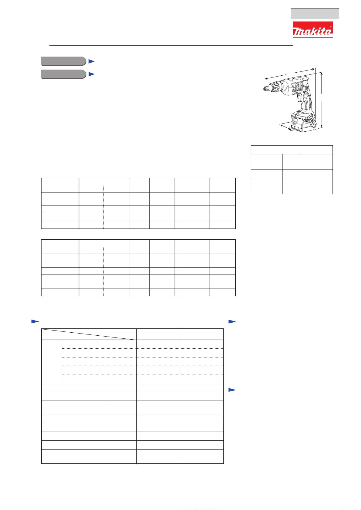
CONCEPT AND MAIN APPLICATIONS
Models BFS441 and BFS451 are pistol grip Cordless Screwdrivers
with variable speed control switch, compact and lightweight body,
well balanced tool design for easy handling and maneuverability,
featuring the following main benefits:
● Best possible tool body for screwdriving
● Compatible with both 1.3Ah and 3.0Ah batteries
● Single LED job light with afterglow function
This model is available in the following variations.
BFS441
Model No.
BFS441Z
BFS441ZX
BFS441RFE
BFS451
Model No.
Battery
Type Quantity
No No NoNoNo No
No No YesNoNo No
BL1430 DC18RA NoYes
BL1430 DC18RA YesNo
Battery
Type Quantity
Battery
cover
2 1
2 1BFS441RFX
Battery
cover
Charger
Charger
carrying case
carrying case
Plastic
Plastic
Systainer
case
Systainer
case
PRODUCT
P 1/14
L
H
W
(The image above is BFS441.)
Dimensions: mm (")
Length (L)
Width (W)
Height (H)
*2: with Magnetic connect bit 60
*3: with Magnetic connect bit 76
*4: with BL1415 or BL1815
*5: with BL1430 or BL1830
281 (11-1/8)*2
296 (11-5/8)*3
80 (3-1/8)
224 (8-7/8)*
241 (9-1/2)*5
4
BFS451Z
BFS451ZX
BFS451RFE
All models also include the accessories listed below in "Standard equipment".
No No NoNoNo No
No No YesNoNo No
DC18RA NoYes
BL1830
BL1830 DC18RA YesNo
2
2 1BFS451RFX
1
Specification
Specification
Voltage: V
Capacity : Ah
Battery Cell
Energy capacity: Wh
Charging time (approx.): min. 15/ 22 with DC18RA
Driver bit: mm (")
Capacities: mm (")
[drywall]
Electric brake Yes
Reverse switch
Variable speed control by trigger
LED job light
Weight according to
EPTA-Procedure 01/2003*
*6: With Battery
Model BFS451BFS441
6: kg (lbs)
14.4 18
1.3/ 3.0
Li-ion
19/ 44 24/ 54
0 - 4,000No load speed: min.-1 = rpm
6.35 (1/4) HexShank
4 (5/32)Diameter
Yes
Yes
Yes
1.4/ 1.6
(3.2/ 3.6)
1.5/ 1.7
(3.3/ 3.8)
Standard equipment
Phillips bit 2-25 ............................ 2
Magnetic connect bit
6.35-60 or 6.35-76 ........................ 1
Belt clip
Note: The standard equipment for
the tool shown above may vary
by country.
........................................ 1
Optional accessories
Phillips bit 1-25
Phillips bit 2-25
Phillips bit 3-25
Magnetic connect bit 6.35-60
Magnetic connect bit 6.35-76
Battery BL1415 for BFS441
Battery BL1430 for BFS441
Battery BL1815 for BFS451
Battery BL1830 for BFS451
Fast charger DC18RA
Charger DC24SC
except North American countries)
Charger DC18SD
Automotive charger DC18SE
(for all countries
P 2/14
Repair
CAUTION: Repair the machine in accordance with “Instruction manual” or “Safety instructions”.
[1] NECESSARY REPAIRING TOOLS
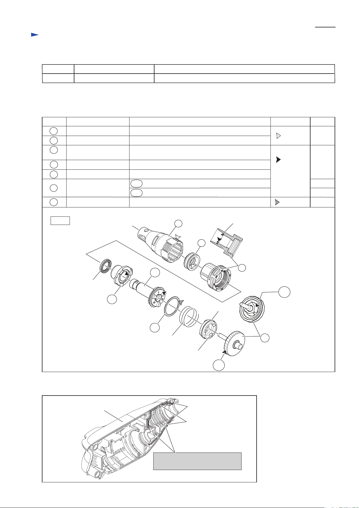
[2] LUBRICANT AND ADHESIVE APPLICATION
Fig. 1
Code No. Description Use for
1R269 Bearing extractor (small) removing Ball bearing 608ZZ
Item No.
Apply the following lubricants to protect parts and product from unusual abrasion. (Fig. 1)
Description Lubricant
VG32
3g
a little
a little
a little
a littleVG100
AmountPortion to lubricate
7
4
3
10
11
Clutch cam
X ring 14
Apply adhesive ThreeBond 1215 to the ribs surrounding gear room of Housing (L) complete. (Fig. 2)
Steel ball 4
18
18A
18A
18B
18B
Compression
spring 25
3
Locator complete Thread portion
4
Makita
grease
FA No.2
Internal surface
Internal surface
7 Locator base Internal surface of Dust seal 13 that Spindle 125S
complete contacts
10
Spindle 125S complete Surface that Clutch cam contacts
11 Flat washer 25 Surface that Compression spring 25 contacts
17 Bearing complete
Gear complete
Teeth portion
Concave for Steel ball 4
17
18
Dust seal sleeve
Dust seal 13
Fig. 2
Housing (L) complete
Apply 1g “ThreeBond 1215”
on the ribs surrounding gear room.
ribs
Apply the bond up to
the end of the ribs.
P 3/14
Repair
[3] DISASSEMBLY/ASSEMBLY
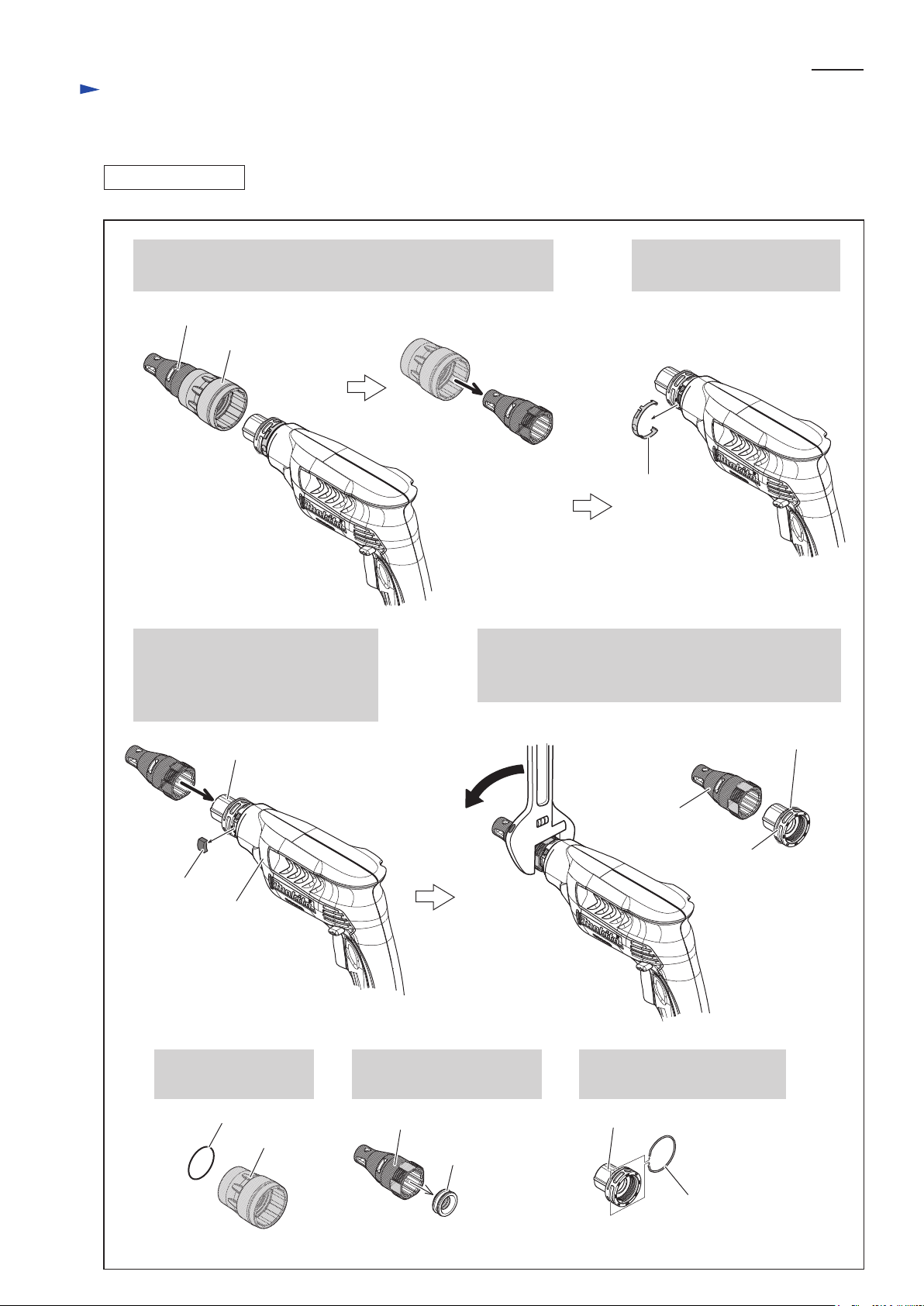
[3]-1. Locator Section
DISASSEMBLING
1. Pull off Locator complete and Lock ring from Housing,
then remove Locator complete from Lock ring.
Locator complete
Lock ring
Leaf spring
Fig. 3
2. Remove Leaf spring with
slotted screwdriver.
3. Remove Rubber plate from
Housing (L) complete.
4. Mount Locator complete back
to Locator base complete.
Rubber plate
Remove Seal ring 30
from Lock ring
Remove Dust seal sleeve
from Locator complete.
Remove ring spring 33
from Locator base complete.
Housing (L) complete
Locator base complete
5. Grip flat portion of Locator complete with
adjustable wrench, then turn it clockwise
to remove Locator base complete from Housing.
Locator base
complete
Ring spring 33
Locator
complete
Locator complete
Dust seal sleeve
Lock ring
Ring spring 33
Seal ring 30
Locator base complete
P 4/14
Repair
[3] DISASSEMBLY/ASSEMBLY
[3]-1. Locator Section
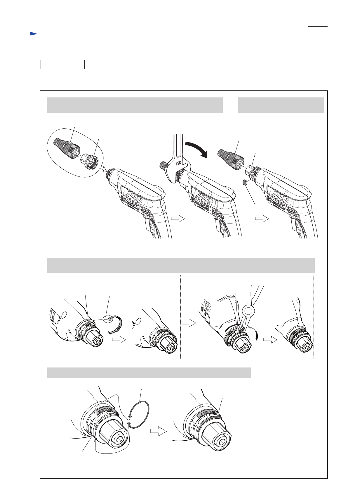
ASSEMBLING
Rubber plate
1) Assembling of Locator base complete, Locator complete, Leaf spring and related parts. (Fig. 4)
1. Mount Locator complete to Locator base complete and fix them
to Housing set by tightening counterclockwise with adjustable wrench.
2. Remove Locator complete again,
then put Rubber plate in place.
Locator base complete
Locator base complete
Locator complete
3. Fit the tab of Leaf spring to Housing top as described below, then fix the other tab of Leaf spring to
Housing bottom with pliers.
4. Fix Ring spring 33 in the groove on Locator base complete as described below.
tab of
Leaf spring
Locator complete
Ring spring 33
Ring spring 33
Fig. 4
Locator base
complete
protrusion on
Housing top
protrusion on
Housing bottom
P 5/14
Repair
[3] DISASSEMBLY/ASSEMBLY
[3]-1. Locator Section
ASSEMBLING
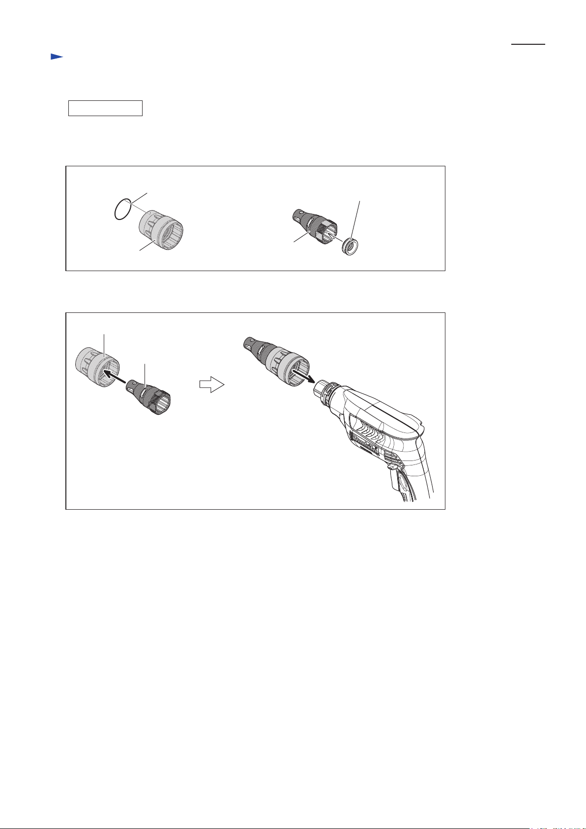
2) Make sure to put Seal ring 30 in Lock ring and Dust seal sleeve in Locator complete
before mount them on Housing. (Fig. 5)
Dust seal sleeve
Seal ring 30
Lock ring
Locator complete
Fig. 5
Locator complete
Lock ring
Fig. 6
3) Insert Locator complete into Lock ring and mount them on Housing. (Fig. 6)
 Loading...