

Page 1
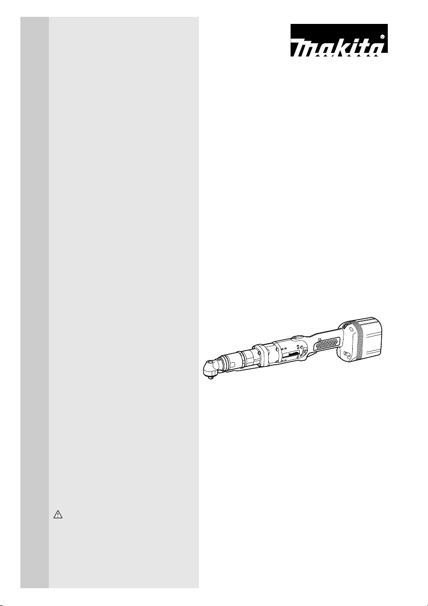
Cordless Angle Nut
Runner
MODEL BFL300F
MODEL BFL400F
INSTRUCTION MANUAL
WARNING:
For your personal safety, READ and UNDERSTAND before using.
SAVE THESE INSTRUCTIONS FOR FUTURE REFERENCE.
005735
Page 2

SPECIFICATIONS
Model BFL300F BFL400F
Fastening
torque
Square drive 9.5 mm (3/8”) 9.5 mm (3/8”)
No load speed (RPM) 400 /min. 260 /min.
Dimensions
(With Battery Cartridge BH1427)
Net weight
(With Battery Cartridge BH1427)
Standard battery cartridge BH1427
• Manufacturer reserves the right to change specifications without notice.
• Specifications may differ from country to country.
Hard joint 16 - 30 N • m (142 - 266 in • lbs) 25 - 40 N • m (221 - 354 in • lbs)
Soft joint 16 - 30 N • m (142 - 266 in • lbs) 25 - 40 N • m (221 - 354 in • lbs)
506 mm x 73 mm x 104 mm
(19-15/16” x 2-7/8” x 4-1/8”)
2.3 kg (5.1 lbs.) 2.4 kg (5.3 lbs.)
510 mm x 73 mm x 104 mm
(20-1/16” x 2-7/8” x 4-1/8”)
GENERAL SAFETY RULES GEA002-1
WARNING:
Read all instructions. Failure to follow all instructions listed below
may result in electric shock, fire and/or serious injury. The term
“power tool” in all of the warnings listed below refers to your mainsoperated (corded) power tool or battery-operated (cordless) power
tool.
SAVE THESE INSTRUCTIONS
Work area safety
1. Keep work area clean and well lit. Cluttered
and dark areas invite accidents.
2. Do not operate power tools in explosive
atmospheres, such as in the presence of
2
flammable liquids, gases or dust. Power
tools create sparks which may ignite the dust
or fumes.
3. Keep children and bystanders away while
operating a power tool. Distractions can
cause you to lose control.
Page 3

Electrical safety
4. Power tool plugs must match the outlet.
Never modify the plug in any way. Do not
use any adapter plugs with earthed
(grounded) power tools. Unmodified plugs
and matching outlets will reduce risk of electric shock.
5. Avoid body contact with earthed or
grounded surfaces such as pipes, radiators, ranges and refrigerators. There is an
increased risk of electric shock if your body is
earthed or grounded.
6. Do not expose power tools to rain or wet
conditions. Water entering a power tool will
increase the risk of electric shock.
7. Do not abuse the cord. Never use the cord
for carrying, pulling or unplugging the
power tool. Keep cord away from heat, oil,
sharp edges or moving parts. Damaged or
entangled cords increase the risk of electric
shock.
8. When operating a power tool outdoors,
use an extension cord suitable for outdoor use. Use of a cord suitable for outdoor
use reduces the risk of electric shock.
Personal safety
9. Stay alert, watch what you are doing and
use common sense when operating a
power tool. Do not use a power tool while
you are tired or under the influence of
drugs, alcohol or medication. A moment of
inattention while operating power tools may
result in serious personal injury.
10. Use safety equipment. Always wear eye
protection. Safety equipment such as dust
mask, non-skid safety shoes, hard hat, or
hearing protection used for appropriate conditions will reduce personal injuries.
11. Avoid accidental starting. Ensure the
switch is in the off-position before plugging in. Carrying power tools with your finger
on the switch or plugging in power tools that
have the switch on invites accidents.
12. Remove any adjusting key or wrench
before turning the power tool on. A wrench
or a key left attached to a rotating part of the
power tool may result in personal injury.
13. Do not overreach. Keep proper footing
and balance at all times. This enables bet-
ter control of the power tool in unexpected situations.
14. Dress properly. Do not wear loose clothing or jewellery. Keep your hair, clothing,
and gloves away from moving parts.
Loose clothes, jewellery or long hair can be
caught in moving parts.
15. If devices are provided for the connection
of dust extraction and collection facilities,
ensure these are connected and properly
used. Use of these devices can reduce dust-
related hazards.
Power tool use and care
16. Do not force the power tool. Use the correct power tool for your application. The
correct power tool will do the job better and
safer at the rate for which it was designed.
17. Do not use the power tool if the switch
does not turn it on and off. Any power tool
that cannot be controlled with the switch is
dangerous and must be repaired.
18. Disconnect the plug from the power
source and/or the battery pack from the
power tool before making any adjustments, changing accessories, or storing
power tools. Such preventive safety mea-
sures reduce the risk of starting the power
tool accidentally.
19. Store idle power tools out of the reach of
children and do not allow persons unfamiliar with the power tool or these instructions to operate the power tool. Power
tools are dangerous in the hands of untrained
users.
20. Maintain power tools. Check for misalignment or binding of moving parts, breakage of parts and any other condition that
may affect the power tools operation. If
damaged, have the power tool repaired
3
Page 4

before use. Many accidents are caused by
poorly maintained power tools.
21. Keep cutting tools sharp and clean. Prop-
erly maintained cutting tools with sharp cutting edges are less likely to bind and are
easier to control.
22. Use the power tool, accessories and tool
bits etc. in accordance with these instructions and in the manner intended for the
particular type of power tool, taking into
account the working conditions and the
work to be performed. Use of the power tool
for operations different from those intended
could result in a hazardous situation.
Battery tool use and care
23. Ensure the switch is in the off position
before inserting battery pack. Inserting the
battery pack into power tools that have the
switch on invites accidents.
24. Recharge only with the charger specified
by the manufacturer. A charger that is suit-
able for one type of battery pack may create a
risk of fire when used with another battery
pack.
25. Use power tools only with specifically
designated battery packs. Use of any other
battery packs may create a risk of injury and
fire.
26. When battery pack is not in use, keep it
away from other metal objects like paper
clips, coins, keys, nails, screws, or other
small metal objects that can make a connection from one terminal to another.
Shorting the battery terminals together may
cause burns or a fire.
27. Under abusive conditions, liquid may be
ejected from the battery, avoid contact. If
contact accidentally occurs, flush with
water. If liquid contacts eyes, additionally
seek medical help. Liquid ejected from the
battery may cause irritation or burns.
Service
28. Have your power tool serviced by a qualified repair person using only identical
replacement parts. This will ensure that the
safety of the power tool is maintained.
- WARNING- To reduce the risk of injury, user must read instruction manual.
ADDITIONAL SAFETY RULES FOR POWER
TOOL
DO NOT let comfort or familiarity with product (gained from
repeated use) replace strict adherence to drill safety rules. If
you use this power tool unsafely or incorrectly, you can suffer
serious personal injury.
1. Hold power tools by insulated gripping
surfaces when performing an operation
where the cutting tool may contact hidden
wiring or its own cord. Contact with a “live”
wire will make exposed metal parts of the tool
“live” and shock the operator.
4
2. Always be sure you have a firm footing.
Be sure no one is below when using the
tool in high locations.
3. Hold the tool firmly.
4. Keep hands away from rotating parts.
GEB002-1
Page 5

5. Do not leave the tool running. Operate the
tool only when hand-held.
6. Do not touch the drill bit or the workpiece
immediately after operation; they may be
extremely hot and could burn your skin.
7. Some material contains chemicals which
may be toxic. Take caution to prevent dust
inhalation and skin contact. Follow material supplier safety data.
SAVE THESE INSTRUCTIONS
WARNING:
MISUSE or failure to follow the safety rules stated in this
instruction manual may cause serious personal injury.
SYMBOLS USD301-1
The followings show the symbols used for tool.
V .......................volts
................... direct current
....................no load speed
n
˚
.../min................revolutions or reciprocation per
minute
IMPORTANT SAFETY INSTRUCTIONS FOR
BATTERY CARTRIDGE
1. Before using battery cartridge, read all instruc-
tions and cautionary markings on (1) battery
charger, (2) battery, and (3) product using battery.
2. Do not disassemble battery cartridge.
3. If operating time has become excessively
shorter, stop operating immediately. It may
result in a risk of overheating, possible burns
and even an explosion.
4. If electrolyte gets into your eyes, rinse them out
with clear water and seek medical attention right
away. It may result in loss of your eyesight.
5. Do not short the battery cartridge:
(1) Do not touch the terminals with any con-
ductive material.
(2) Avoid storing battery cartridge in a con-
tainer with other metal objects such as
nails, coins, etc.
(3) Do not expose battery cartridge to water or
rain.
A battery short can cause a large current flow,
overheating, possible burns and even a breakdown.
ENC005-1
5
Page 6

6. Do not store the tool and battery cartridge in
locations where the temperature may reach or
exceed 50°C (122°F).
7. Do not incinerate the battery cartridge even if it
8. Be careful not to drop or strike battery.
SAVE THESE INSTRUCTIONS
Tips for maintaining maximum battery life
1. Charge the battery cartridge before completely
discharged.
Always stop tool operation and charge the battery cartridge when you notice less tool power.
2. Never recharge a fully charged battery cartridge.
Overcharging shortens the battery service life.
3. Charge the battery cartridge with room tempera-
ture at 10°C - 40°C (50°F - 104°F). Let a hot battery cartridge cool down before charging it.
4. Charge the Nickel Metal Hydride battery car-
tridge when you do not use it for more than six
months.
is severely damaged or is completely worn out.
The battery cartridge can explode in a fire.
6
Page 7

FUNCTIONAL
DESCRIPTION
1
2
3
1. Battery cartridge
2. Red part
3. Button
1
1. Switch trigger
CAUTION:
• Always be sure that the tool is switched off and the
battery cartridge is removed before adjusting or
checking function on the tool.
005736
Installing or removing battery cartridge
• Always switch off the tool before insertion or removal of
the battery cartridge.
• To remove the battery cartridge, withdraw it from the tool
while sliding the button on the front of the cartridge.
• To insert the battery cartridge, align the tongue on the
battery cartridge with the groove in the housing and slip
it into place. Always insert it all the way until it locks in
place with a little click. If you can see the red part on the
upper side of the button, it is not locked completely.
Insert it fully until the red part cannot be seen. If not, it
may accidentally fall out of the tool, causing injury to you
or someone around you.
• Do not use force when inserting the battery cartridge. If
the cartridge does not slide in easily, it is not being
inserted correctly.
005737
Switch action
CAUTION:
• Before inserting the battery cartridge into the tool,
always check to see that the switch trigger actuates
properly and returns to the “OFF” position when
released.
To start the tool, simply pull the switch trigger. Release the
switch trigger to stop.
A
1
1
1. Reversing switch lever
B
005738
Reversing switch action
CAUTION:
• Always check the direction of rotation before operation.
• Use the reversing switch only after the tool comes to a
complete stop. Changing the direction of rotation before
the tool stops may damage the tool.
• When not operating the tool, always set the reversing
switch lever to the neutral position.
7
Page 8

2
1. Lamp
2. LED indicator
This tool has a reversing switch to change the direction of
rotation. Depress the reversing switch lever from the A side
for clockwise rotation or from the B side for counterclockwise
rotation.
When the reversing switch lever is in the neutral position, the
switch trigger cannot be pulled.
005739
Lighting up the lamps
CAUTION:
• Do not look in the light or see the source of light directly.
Pull the switch trigger to light up the lamp. The lamp keeps
1
on lighting while the switch trigger is being pulled. The light
automatically goes out 10 seconds after the switch trigger is
released.
NOTE:
• Use a dry cloth to wipe the dirt off the lens of lamp. Be
careful not to scratch the lens of lamp, or it may lower the
illumination.
8
Page 9

LED indicator / Beeper
Led indicator / Beeper on the tool shows the following functions.
Function Status
Auto-stop
fastening
Delayed re-start
Warning against
insufficient
fastening
Warning for
battery cartridge
capacity
Checking the
remaining battery
capacity,
Autostop
Check the LED
indicator, light
and beeper
operation
Anti-reset of
controller
Overheat
Operation error of
the switch trigger
Motor malfunction
This function works when the tool
has reached the preset fastening
torque and normal tightening has
been completed. This helps
overtightening to be avoided.
For approximately one second
after auto-stop fastening, the tool
does not start even if the switch
trigger is pulled.
Insufficient fastening has been
performed when the switch
trigger has released before
reaching the preset fastening
torque.
This indicates the appropriate
time to replace the battery
cartridge when the battery power
becomes low.
This function works when the
battery power is almost used up.
At this time, tool stops
immediately.
This function works to check the
proper operation of the LED
indicator, light and beeper when
a battery cartridge has been
inserted into the tool.
This function works when an
abnormal drop of the battery
voltage occurs for some reason,
and the tool stops.
This function works if the
temperature of the controller or
motor increases to a high level
and the tool stops.
This function works to avoid the
tool's immediate start upon
insertion of battery cartridge into
the tool with the switch trigger
being pulled.
This indicates the abnormal
condition of the motor. The tool
does not operate.
Status of the LED indicator/beeper
LED indicator Beeper
Lights up in green
for approximately
one second.
–
Lights up in red.
Flickers in red
slowly.
Lights up in red.
Lights up first in
green, next red.
(And then the light
comes on.)
Flickers in red and
green alternatively.
Flickers in red
quickly.
Flickers in red and
green alternatively.
Flickers in red and
green
alternatively.
A long beep
A series of long
beeps
A long beep
A series of very
short beeps
A series of short
beeps
A series of short
beeps
A series of short
beeps
A series of short
beeps
003814
Action to be taken
–
Retighten the screw
Replace the battery
with fully charged
one
Replace the battery
with fully charged
one
–
Replace the battery
with fully charged
one
Remove the battery
cartridge
immediately and
cool the tool down.
Release the switch
trigger.
Ask Makita service
centers.
9
Page 10

1
1. Screw
1
005750
Adjusting the fastening torque
When you wish to drive machine screws, wood screws, hex
bolts, etc. with the predetermined torque, adjusting the fastening torque as follows.
1. First remove the battery cartridge from the tool.
2. Loosen and remove the screw that secures ring.
3. Rotate the ring in the front of the tool by hand so that a
hole can be seen below the ring.
005740
7
2
3
4
1. Angle head
2. Ring
3. Scale
4. Compression spring
5. Yellow line
6. Hole for adjusting grip
7. Adjusting grip
6
5
005741
4. Place the battery cartridge in place and pull the switch
trigger. Release it so that the adjusting ring rotates and
becomes visible in the hole. And then remove the battery
cartridge.
5. Use an optional adjusting grip to adjust the fastening
torque. Insert the pin of the adjusting grip into the hole in
the front of the tool. And then, turn the adjusting grip
clockwise to set a greater fastening torque, and counterclockwise to set a smaller fastening torque.
6. Align the edge of the adjusting ring with your desired
number on the fastening torque scale.
7. Insert the battery cartridge and be sure that a fastening
torque has been set up by using a fastening torque
tester.
8. Rotate the ring so that the hole for adjusting grip is covered, hold and then secure the ring with screw.
NOTE:
• Numbers on the fastening torque scale is a guideline to
set up your desired fastening torque.
10
Page 11

ASSEMBLY
1
2
3
1. Socket
2. Hole
3. Pin
CAUTION:
• Always be sure that the tool is switched off and the
battery cartridge is removed before carrying out any
work on the tool.
Selecting correct socket
There are different types of sockets for some models
depending on applications. Choose and install a correct
socket for your application.
005742
Installing or removing socket
To install the socket, push it onto the square drive of the tool
with one hand by depressing a pin on the square drive with
another hand until it locks into place. To remove the socket,
simply pull it off depressing the pin on the square drive.
OPERATION
Hold the tool firmly and place the socket over the bolt or nut.
Then switch the tool on. When the clutch cuts in, the motor
will stop automatically. Then release the switch trigger.
NOTE:
• Hold the tool with its square drive pointed straight at the
bolt or nut, or the bolt or nut will be damaged.
• Use of a low temperature conditioned battery cartridge
may sometimes give warning for battery cartridge
capacity by warning lamp and beeper which makes the
tool stop immediately. In this case, the range of fastening
capacity may be inferior to those shown in the above
even if a charged battery cartridge is used.
11
Page 12

MAINTENANCE
CAUTION:
• Always be sure that the tool is switched off and the
battery cartridge is removed before attempting to
perform inspection or maintenance.
To maintain product SAFETY and RELIABILITY, repairs, any
other maintenance or adjustment should be performed by
Makita Authorized or Factory Service Centers, always using
Makita replacement parts.
ACCESSORIES
CAUTION:
• These accessories or attachments are recommended for
use with your Makita tool specified in this manual. The
use of any other accessories or attachments might
present a risk of injury to persons. Only use accessory
or attachment for its stated purpose.
If you need any assistance for more details regarding these
accessories, ask your local Makita service center.
• Protector (Yellow,Blue,Red,Clear)
• Various type of Makita genuine batteries and chargers
• Automatic refreshing adapter
• Adjust grip
• Switch lever set
• Spindle complete 12.7
12
Page 13

Cut
Makita Canada Inc.
1950 Forbes Street,
Whitby, Ontario
L1N 7B7
Fold
Stamp
Timbre
13
Page 14

Your answers to the following questions are appreciated.
1. This product was purchased from?
Hardware/lumber Store
2. Use of the product is intended for?
Construction trade
5. Any comments?
Industrial Supply
Other ( )Tool Distributor
Home maintenance
Other ( )Industrial maintenance
3. How did you first learn of Makita Power Tools?
4. Most favored points are?
Certificate of Warranty
Mail to Makita
Date Purchased Model No.
Month Day Year 20
Serial No.
Magazine/Newspaper
Store display
Design
Price
Catalog
Other ( )From dealer
Makita Brand
Powe rFeatures
Other ( )Size
Initial Last Name
Street Address
City Province
AGE:
Under 19 20-29 30-39 40-49 Over 50
Occupation:
Dealer's Name & Address:
Paste Paste Paste Paste Paste Paste
14
Paste Paste Paste Paste Paste Paste Paste Paste
Male Female Marr iedSingle
Postal Code
Paste Paste Paste Paste Paste Paste
Page 15

Factory Service Centres
Head Office: 1950 Forbes St., Whitby, Ontario, L1N 7B7
Regional Office: 11771 Hammersmith Way, Richmond
Regional Office: 6389 boul. Couture, St. Leonard, Quebec
Dartmouth: 202 Brownlow Avenue
Ville St. Laurent: 1140 Rue Bégin, Ville St. Laurent, Quebec
Les Saules: 1200 St. Jean Baptiste, Unit 106, Les Saules,
Nepean: 210 Colonnade Road, Unit 11, Nepean,
Whitby: 1950 Forbes St., Whitby, Ontario, L1N 7B7
London: 317 Adelaide St. S., Unit 117, London,
Mississauga: 6350 Tomken Rd., Unit 8, Mississauga,
Calgary: #8-6115 Fourth St. S.E., Calgary
Edmonton: 11614-149 Street, Edmonton, Alberta,
Richmond: 11771 Hammersmith Way, Richmond, B.C.,
Winnipeg: 1670 St. James Street, Winnipeg, Manitoba,
Saskatoon: 206A-2750 Faithful Avenue Saskatoon,
For the authorized service centre nearest you please refer to the local yellow pages directory under “tools” or contact our customer service department (Tel) 1-800-263-3734
(905) 571 - 2200 1-800-263-3734
(604) 272 - 3104 1-800-663-0909B.C. V7A 5H6
(514) 323 - 1223 1-800-361-7049H1P 3J5(Montreal)
(902) 468 - 7064 1-888-625-4821Dartmouth, N.S., B3B 1T5
(514) 745 - 5025 1-888-745-5025H4R 1X1(Montreal)
(418) 871 - 5720 1-800-663-5757Quebec, G2E 5E8(Quebec)
(613) 224 - 5022 1-888-560-2214Ontario, K2E 7M1(Ottawa)
(905) 571 - 2200 1-800-263-3734
(519) 686 - 3115 1-800-571-0899Ontario, N5Z 3L3
(905) 670 - 7255 1-888-221-9811Ontario, L5T 1Y3
(403) 243 - 3995 1-800-267-0445Alberta, T2H 2H9
(780) 455 - 6644 1-888-455-6644T5M 3R3
(604) 272 - 3104 1-800-663-0909V7A 5H6
(204) 694 - 0402 1-800-550-5073R3H 0L3
(306) 931 - 0111 1-888-931-0111Saskatchewan, S7K 6M6
CUSTOMER RECORD
When you need service...
• Explain the problem in a letter
• Enclose the letter with the tool
• Package carefully and send prepaid
to the nearest Makita factory or
authorized service centre
DATE
PURCHASED:
DEALER’S NAME
& ADDRESS:
MODEL NO.:
SERIAL NO.:
15
Page 16

MAKITA LIMITED ONE YEAR WARRANTY
Warranty Policy
Every Makita tool is thoroughly inspected and tested before leaving the factory. It is warranted to be free of defects from
workmanship and materials for the period of ONE YEAR from the date of original purchase. Should any trouble develop during
this one year period, return the COMPLETE tool, freight prepaid, to one of Makita’s Factory or Authorized Service Centres.
If inspection shows the trouble is caused by defective workmanship or material, Makita will repair (or at our option, replace)
without charge.
This Warranty does not apply:
• where normal maintenance is required,
• repairs have been made or attempted by others,
• the tool has been abused, misused or improperly maintained,
• alterations have been made to the tool.
IN NO EVENT SHALL MAKITA BE LIABLE FOR ANY INDIRECT, INCIDENTAL OR CONSEQUENTIAL DAMAGES FROM
THE SALE OR USE OF THE PRODUCT. THIS DISCLAIMER APPLIES BOTH DURING AND AFTER THE TERM OF THIS
WARRANTY.
“The Makita Warranty is the only and the entire written warranty given by Makita for the Makita tools. No dealer or his agent
or employee is authorized to extend or enlarge upon this warranty by any verbal or written statement or advertisement.”
MAKITA DISCLAIMS LIABILITY FOR ANY IMPLIED WARRANTIES INCLUDING IMPLIED WARRANTIES OF
“MERCHANTABILITY” AND FITNESS FOR A SPECIFIC PURPOSE,” AFTER THE ONE YEAR TERM OF THIS WARRANTY.
“This Warranty gives you specific rights. The provisions contained in this warranty are not intended to limit, modify, take away
from, disclaim or exclude any warranties set forth in any provincial legislation. To the extent required by law, the provisions in
any provincial or federal legislation with respect to warranties take precedence over the provisions in this warranty.”
884551-237
Makita Corporation
3-11-8, Sumiyoshi-cho,
Anjo, Aichi 446-8502 Japan
 Loading...