

Page 1
T
ECHNICAL INFORMATION
Models No.
BFL300F, BFL400F, BFL401F
NEW TOOL
P 1 / 13
Description
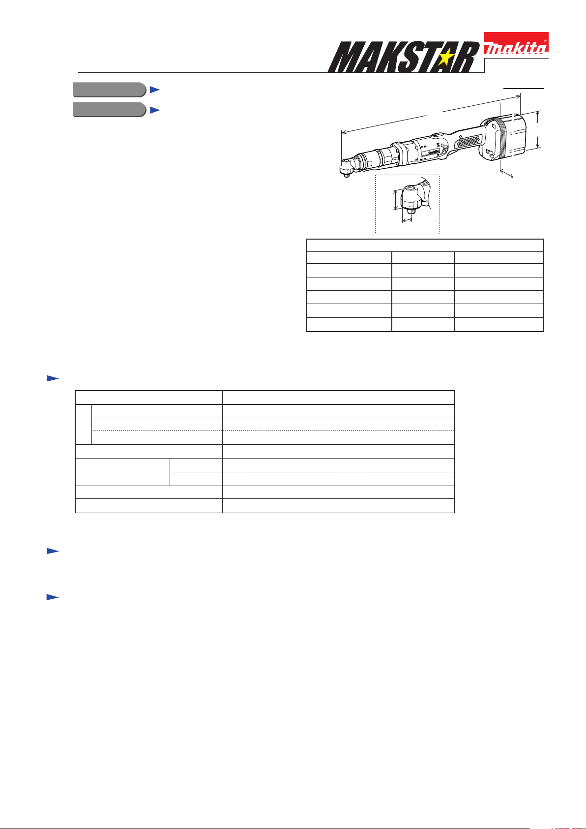
Cordless Angle Screwdriver 14.4V
CONCEPT AND MAIN APPLICATIONS
Models BFL300F and BFL400F have been developed
as specialist tools for industrial assembly applications,
featuring high torque capacity of 30N.m (BFL300F)/
40N.m (BFL400F).
Their brief advantages are;
*High precision fastening
*DC brushless motor for increased no load speed
*14.4V, 2.7Ah Ni-MH battery equipped with new type
battery cells for more efficient energy supply to motor
Model BFL401F is a sister tool designed for Italy.
These models do not include battery and charger.
Specification
HH
Model No.
Length (L)
Width (W)
Height (H)
Head height (HH)
Center height (CH)
L
CH
Dimensions: mm (")
BFL300F
506 (20) 510 (20-1/16)
73 (2-7/8)
104 (4-1/8)
31.5 (1-1/4)
16 (5/8)
*Battery is optional.
BFL400F/ BFL401F
104 (4-1/8)
34 (1-5/16)
H
W
73 (2-7/8)
18 (11/16)
BFL300F
Voltage: V
Capacity: Ah
Battery
Cell
Capacity 9.5mm (3/8") Square drive*
Fastening torque: N.m
No load speed: min.-1=rpm
Net weight: kg (lbs)
*Note: 12.7mm (1/2") with optional Spindle G complete
Hard joint
Soft joint
16 - 30 25 - 40
16 - 30 25 - 40
400 260
2.3 (5.1) 2.4 (5.3)
Ni-MH
BFL400F/ BFL401FModel No.
14.4
2.7
Standard equipment
No (however, with Protector for some countries, and with Torque adjust tool for some countries)
Optional accessories
Ni-MH battery BH1427
Chargers DC24SA, DC14SA, DC14SC
Automatic refreshing adapter ADP03
Switch lever set (paddle switch)
Spindle G complete (12.7mm square drive)
Protectors Red, Blue, Yellow, Clear
Torque adjust tool
Page 2
Repair
Warning: Always be sure to disconnect battery cartridge from the machine before starting repair.
Note: See the instruction manual for safety instructions, safety rules and operating instructions.
-- Contents --
[1] Necessary Repair Tools ..................................................................................... III - 1
[2] Grease and Adhesive ......................................................................................... III - 1
[3] Disassembling/ Assembling .............................................................................. III - 2
[3] -1. Disassembling/ Assembling of Job Light Section ................................... III - 2, 3
[3] -2. Disassembling/ Assembling of Bearing Retainer .................................... III - 3
[3] -3. Disassembling/ Assembling/ Adjustment of Angle Head Section ........... III - 3, 4
[3] -4. Disassembling/ Assembling of Clutch Case Section ............................... III - 4, 5
[3] -5. Disassembling/ Assembling of Clutch Section ........................................ III - 5
[3] -6. Disassembling/ Assembling of Gear Case Section .................................. III - 5 -7
[3] -7. Disassembling/ Assembling of Switch Section ........................................ III - 7, 8
[1] NECESSARY REPAIR TOOLS
(Code No.) (Tool Name)
1R004 Retaining Ring Pliers ST-2
1R005 Retaining Ring Pliers RT-2N
1R006 Retaining Ring Pliers RT-2E
1R008 Tips for Retaining Ring Pliers
1R033 Bearing setting Plate 10.2
1R219 Torque Wrench Shaft 7-23N.m
1R220 Ratchet Head 9.5
1R222 Socket Adapter
(Code No.) (Tool Name)
1R223 Torque Wrench Shaft 20-90N.m
1R269 Bearing Extractor
1R291 Retaining Ring S and R Pliers
1R341 Spanner Head
134844-7 Socket 27-50 Ass'y
134848-9 Socket 27-50 Ass'y
765025-8 Torque Adjust Tool
P 2 / 13
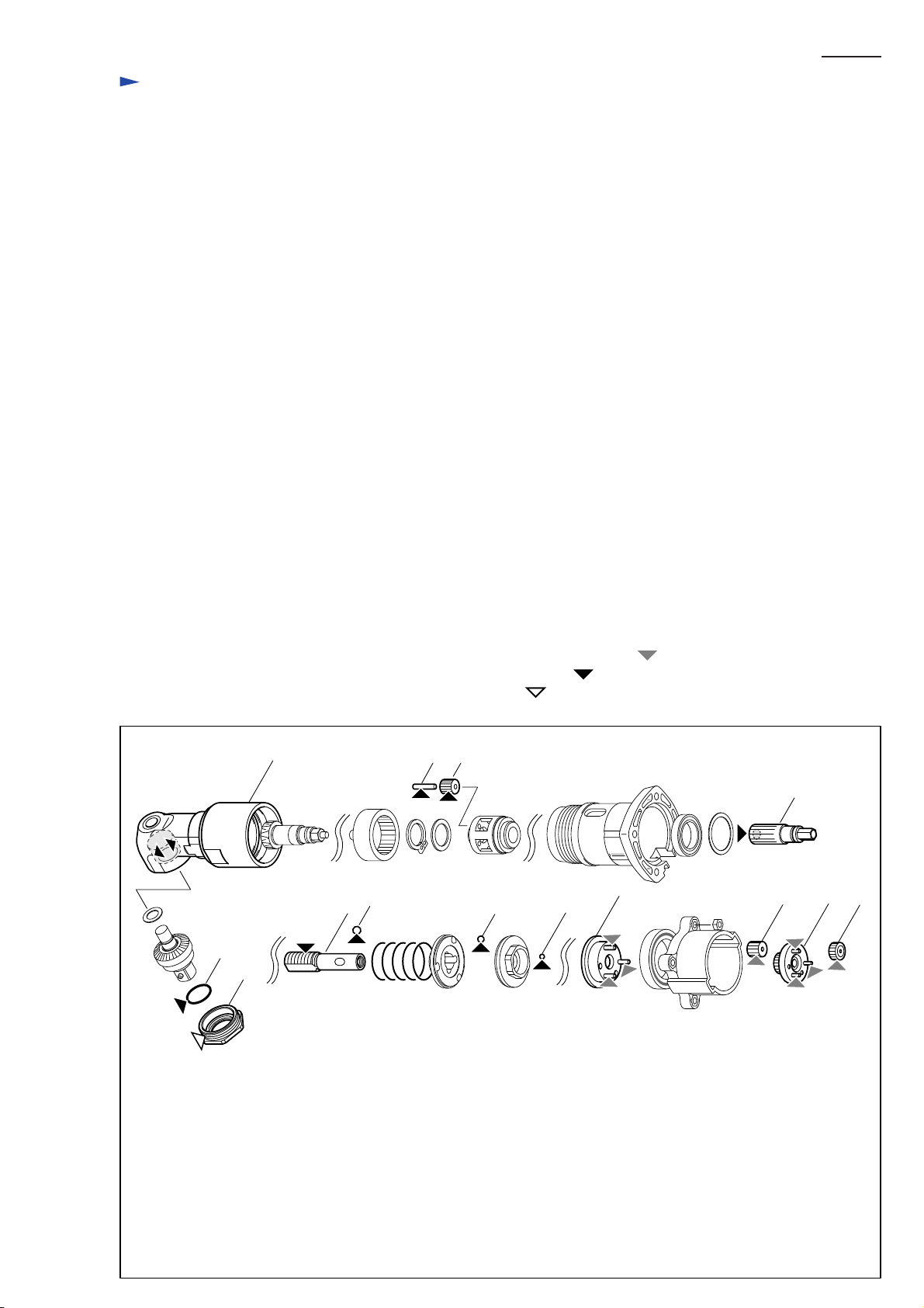
[2] LUBRICATION AND ADHESIVE
See the parts breakdown below.
Apply 2.0g of Makita Grease N. No.2 to the portions designated with the mark of .
Apply Makita seal lubricant to the portions designated with the mark of .
Apply Loc-Tite 603 to the portions designated with the mark of .
Fig. 1
63
64
10
39
40
2221
48
43 45
31
51 52 53
The portions to lubricate with Makita
Seal Lubricant No. 101
10. Gear room of Angle Head Complete
21. Pin 3 (5 pcs)
22. Teeth of Spur Gear 14
31. Hole on Spur Gear 21
39. Threads on Spindle
40. Steel Ball 5.0 (3 pcs)
43. Steel Ball 4 (3 pcs)
45. steel ball 3 (13 pcs)
63. O Ring 15
The portions to lubricate with Makita Grease N No.2
48. Three gear shafts of Carrier Complete (A)
51. Spur Gear 13 (3 pcs)
52. Spur Gear 20 Complete
53. Spur Gear 15 (3 pcs)
The portions to apply Loc-Tite 603
36. Threaded portion of Bearing Retainer 15-26
Page 3
P 3 / 13
[3] DISASSEMBLING/ ASSEMBLING
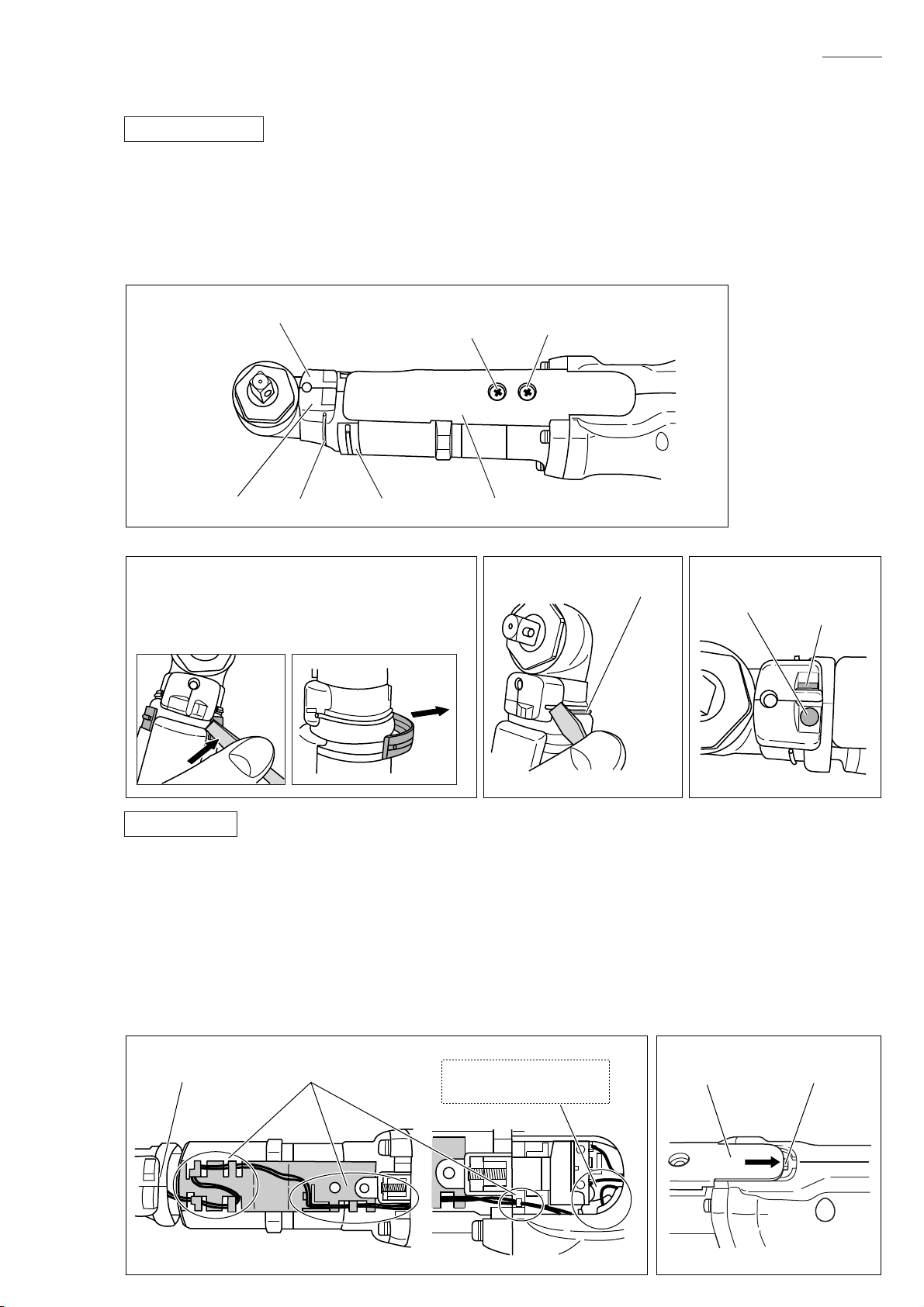
[3] -1. Disassembling/ Assembling of Job Light Section
DISASSEMBLING
*Shown in Fig. 2 are the parts of Job light section.
1) Remove Lead cover (on which Ring spring 36 is installed) and Ring spring 29 using a slotted screwdriver. (Figs. 3, 4)
2) Remove Light covers (R) and (L) while pushing the portion designated with the gray circle to unlock the tab on
Light cover (R) from the slot in (L). (Fig. 5)
3) Separate Switch cover from the tool by removing two M4x8 Pan head screws.
4) Remove Lead wires and LED circuit from Lead wire holders and Light cover (R), and disconnect Connector. (Fig. 6)
Fig. 2
Light cover (L)
Light cover (R)
Fig. 3 Fig. 4 Fig. 5
Push the end face of Lead cover using a slotted
screwdriver till it is lifted up as illustrated to left
below. Now Lead cover can be removed by pulling
in the direction o the arrow as illustrated to right.
Ring spring 29
Pan head screw M4x8
(for fixing Ring 38)
Lead cover Switch cover
Pan head screw M4x8
(for fixing Switch cover)
Ring spring 29
Push here.
tab
ASSEMBLING
1) Fix Lead wires securely with Lead wire holders, and then install LED circuit on Light cover (R).
At this time, put the sag of Lead wires in place as illustrated to right in Fig. 6.
2) Push the tab on Light cover into the cut in Housing before fastening screws. And then fasten Switch cover with two
M4x8 Pan head screws. Be careful not to pinch the Lead wires at this time. (Figs. 2, 7)
3) Install Light covers (R) and (L) while locking the tab on Light cover (R) in the slot in (L), then Ring spring 29. (Fig. 5)
Ring spring 29 can be easily installed by fixing one end on the groove in Light cover, then pushing toward Light cover
while expanding the other end. (Fig. 8)
4) Being careful not to pinch the Lead wires from LED circuit, install Lead cover (on which Ring spring 36 is installed)
as illustrated in Fig. 9.
Fig. 6 Fig. 7
LED circuit Lead wire holders Switch cover tab
Put the sag of Lead wires
in this portion.
Page 4
P 4 / 13
[3] -1. Disassembling/ Assembling of Job Light Section (cont.)
Fig. 8 Fig. 9
Lead cover
Ring spring 36
Lead wire
Ring spring 29
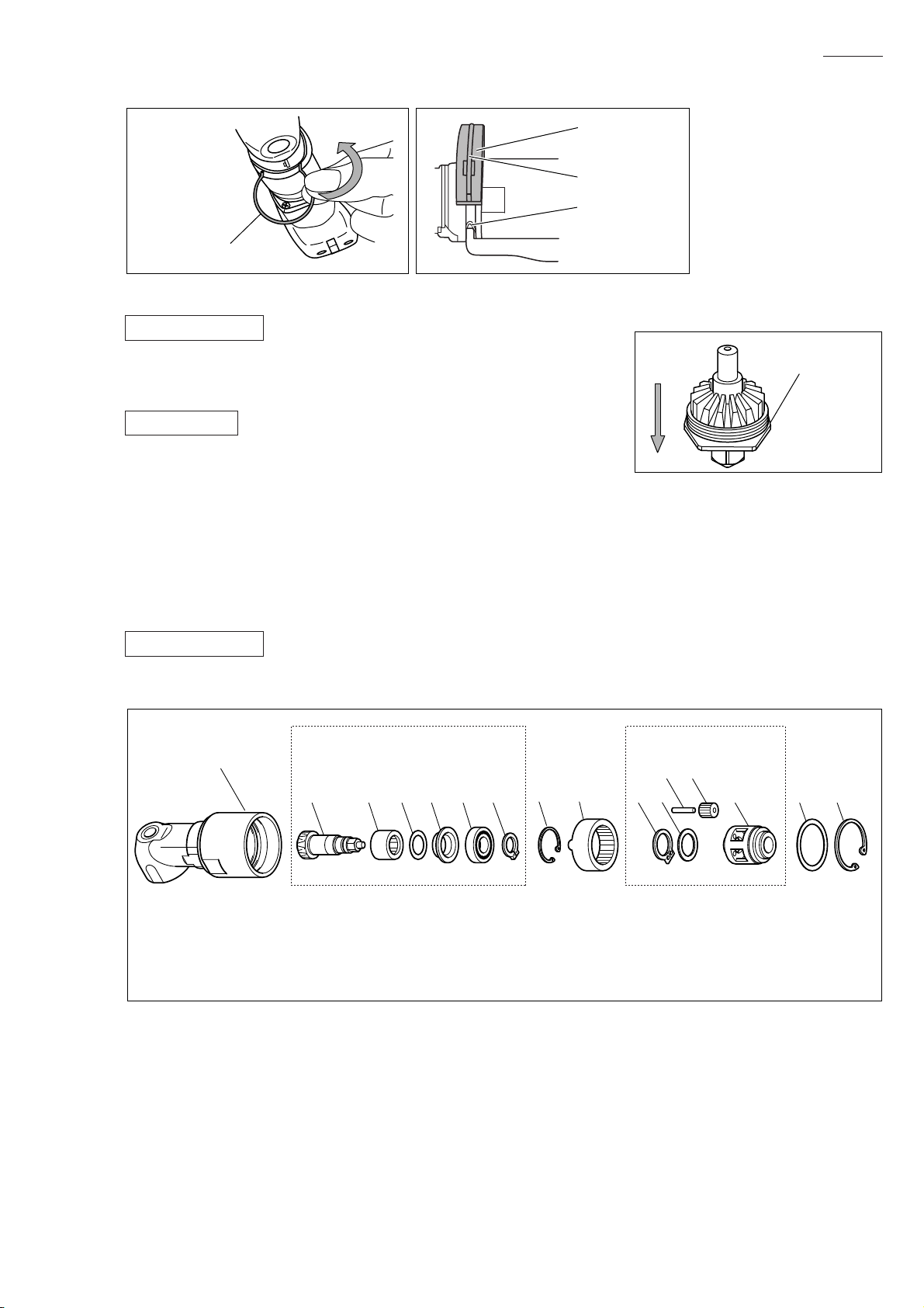
[3] -2. Disassembling/ Assembling of Bearing Retainer
DISASSEMBLING
Turn Bearing retainer clockwise using a 27mm spanner for BFL300F/ 32mm
spanner for BFL400F and BFL401F. Now Bearing retainer can be removed
by pushing it down as illustrated in Fig. 10.
ASSEMBLING
1) After applying Makita seal lubricant No.101 to O ring 15, put O ring 15 and
Bearing retainer in place on Spindle complete.
2) Put 2g of Makita seal lubricant No.101 in the gear room of Angle head complete.
At this time, be careful not to put the grease on the threaded portion of Angle head complete.
3) Apply Loctite 603 to the threaded portion of Bearing retainer, and screw it into Angle head complete.
At this time, remember to put Flat washer 5 in place.
4) Fasten Bearing retainer to the recommended torque of 30 - 50N.m by turning counterclockwise with the following tools;
1R219, 1R220, 1R222, 134844-7 (for BFL300F), 134848-9 (for BFL400F/ BFL401F)
Fig. 10
Bearing retainer
[3] -3. Disassembling/ Assembling/ Adjustment of Angle Head Section
DISASSEMBLING
*Shown in Fig. 11 are the parts of Angle head section.
Fig. 11
10
10) Angle head complete
11) Spiral bevel gear 9
12) Needle bearing 1212
13) Thin washer 12
14) Spacer
1) Remove Light covers (R) and (L), Ring spring 29, Lead cover and Switch cover. (Refer to [3] -1.)
2) Fix Angle head by clamping its two flats using adjustable wrench or vise, and remove Hex nut M36-41 by turning
in the direction of the arrow with 1R223 and 1R341. (Figs. 12, 13)
Caution: When clamping Bearing retainer, be very careful not to deform it by overtightening.
3) Remove Angle head complete by turning counterclockwise.
4) Remove Retaining ring R-32 using 1R006 or the like, then Flat washer 26, Internal gear 50 and Carrier section.
5) Remove Retaining ring S-14 from Carrier section using 1R291 or the like. Now the following parts can be replaced;
Flat washer 14, Pin 3 (5pcs), Spur gear 14 (5pcs)
Note: Pin 3 can be pulled out easily by using a magnet.
6) Remove Retaining ring R-22 located inside Angle head complete using 1R005 or the like.
7) Remove Spiral bevel gear 9 section by hitting the end face of Angle head complete. (Fig. 14)
8) Remove Retaining ring S-10 from Spiral bevel gear 9 section using 1R004, 1R008 or the like.
Now the following parts can be replaced by removing Ball bearing 6900LLB with 1R269 or the like:
Spiral bevel gear 9, Spacer, Thin washer 12, Needle bearing 1212
Spiral bevel gear 9 section Carrier section
21 22
11 12 13 14 15 16 17 18 19 20 23 24 25
15) Ball bearing 6900LLB
16) Retaining ring S-10
17) Retaining ring R-22
18) Internal gear 50
19) Retaining ring S-14
20) Flat washer 14
21) Pin 3 (5pcs)
22) Spur gear 14 (5pcs)
23) Carrier
24) Flat washer 26
25) Retaining ring R-32
Page 5

[3] -3. Disassembling/ Assembling/ Adjustment of Angle Head Section (cont.)
Fig. 12 Fig. 13 Fig. 14
P 5 / 13
two flats
Angle head complete
ASSEMBLING
1) Assemble Needle bearing 1212, Thin washer 12 and Spacer to Spiral
bevel gear 9.
Caution: Spacer is not reversible when assembled to Spiral bevel gear 9.
Be sure to place as illustrated in Fig. 11.
2) Press-fit Ball bearing 6900LLB to Spiral bevel gear 9 using arbor press
and 1R033. Assemble Retaining ring S-14 to Spiral bevel gear 9
to complete assembling of Spiral bevel gear 9 section.
And then insert Spiral bevel gear 9 section into Angle head complete.
3) Assemble Retaining ring R-22 to Spiral bevel gear 9.
4) Put Internal gear 50 in Angle head complete so that the protrusions on
Internal gear 50 fit in the matching holes on Angle head complete.
(Fig. 15)
5) Assemble Spur gear 14 and Pin 3 (5 pcs each) to Carrier, and then Thin washer 14 and Retaining ring S-14 to complete
Carrier section.
6) Insert Carrier section into Angle head complete, and apply 1.5g of Makita seal lubricant No.101 to Spur gear 14.
7) Install Flat washer 26 and Retaining ring R-32.
No.1R223
No.1R341
Adjustable wrench
Fig. 15
protrusion
Internal gear 50
matching hole
Angle head complete
ADJUSTMENT
1) Fasten Angle head complete and Hex nut M36-41 to Clutch case section to the full by hand.
2) Turn Angle head complete counterclockwise to adjust to a desired angle.
3) Being very careful not to turn Angle head complete, fix it securely by turning Hex nut M36-41 clockwise with 1R223
and 1R341 to the recommended torque of 30 -50N.m.
4) Make sure that Lead wires are fixed in place with Lead wire holders as illustrated in Fig. 6.
Then, being careful not to pinch Lead wires, install Lead cover.
[3] -4. Disassembling/ Assembling of Clutch Case Section
DISASSEMBLING
*Shown in Fig. 16 are the parts of Clutch case
section.
1) Remove Angle head section. (Refer to [3]-1, 3.)
2) Remove Compression spring 2 and Switch lever.
3) Clutch case, Clutch assembly and Compression
spring 5 can be removed by removing four
M4x22 Pan head screws.
4) Remove Retaining ring R-26 using 1R006
or the like.
5) Push out Spur gear 21, and then, after removing
Flat washer 21 using slotted screwdriver or
the like, push out Ball bearing 6803ZZ.
6) Remove Retaining ring S-10 using 1R004 and
1R008 or the like, then Ball bearing 6000DDW
using 1R269 or the like.
Now Spur gear 21 can be replaced.
7) Remove Hex nut M36-41 by turning
counterclockwise. Remove Ring 38, and now
Clutch case can be replaced.
Fig. 16
28
69 70 71
28) Clutch case
29) Ball bearing 6803ZZ
30) Flat washer 21
31) Spur gear 21
32) Ball bearing 6000DDW
33) Retaining ring S-10
29 30 31 32 33 34 35
34) Retaining ring R-26
35) Compression spring 5
69) P.H. Screw M4x22 (4pcs)
70) Compression spring 2
71) Switch lever
Page 6

[3] -4. Disassembling/ Assembling of Clutch Case Section (cont.)
ASSEMBLING
1) Press-fit Ball bearing 6000DDW to Spur gear 21 using arbor press and 1R033 or the like,
then install Retaining ring S-10 on Spur gear 21.
2) Into Clutch case, insert first Ball bearing 6803ZZ, next Flat washer 21, and third Spur gear 21.
Then install Retaining ring R-26.
Remark: Remember to place Compression spring 5 between Clutch case and Clutch assembly.
3) Put an appropriate amount of Makita seal lubricant in the hole on Spur gear 21. (Fig. 1)
[3] -5. Disassembling/ Assembling of Clutch Section
Note: When repairing Clutch section, it is recommended to entirely replace Clutch assembly with fresh one.
However, if required to replace component parts of Clutch assembly, follow the disassembling/assembling
procedure described below
P 6 / 13
DISASSEMBLING
1) Remove Clutch case section, and take Clutch section out of
the machine. (Refer to [3]-1, 3, 4.)
2) Insert Torque adjust toll into the hole of Adjust ring complete,
and turn it counterclockwise to remove Lock nut M12.
Decrease in the pressure of Compression spring 19 allows
you to remove Lock nut M12 by turning it clockwise by
hand. (Fig. 17)
3) Remove Adjust ring complete, Flat washer and Compression
spring 19 from Spindle.
4) While shifting the positions of Cam A and Cam D, replace
Steel ball 3.0 (13 pcs.), Steel ball 4.0 (3 pcs.)
and Steel ball 5.0 (3 pcs.).
Steel balls can be removed easily by using a magnet.
ASSEMBLING
1) Apply Makita seal lubricant No. 101 to Steel ball 5.0
(3 pcs.), Steel ball 4.0 (3 pcs.) and Steel ball 3.0
(13 pcs.), and set these Steel balls in place on the Cams.
(Fig. 18)
2) Apply Makita seal lubricant No. 101 to the male threads
on Spindle, and then assemble Compression spring 19,
Flat washer and Adjust ring complete to Spindle,
and then secure Lock nut M12 to Spindle by turning it
counterclockwise using Torque adjust tool, etc.
Fig. 18
Fig. 17
Adjust ring complete
Flat washer
Cam D
Cam A
Compression spring 19
Steel ball 3.0 (13 pcs)
Lock nut M12
Turn Torque adjust tool
counterclockwise.
Steel ball 5.0 (3 pcs)
Cam A
Threads on Spindle
[3] -6. Disassembling/ Assembling of Gear case Section
DISASSEMBLING
1) Remove Switch lever, Switch cover and Compression spring 2. (Refer to [3] -1.)
2) Remove four M4x22 Pan head screws to separate Clutch case from the machine.
3) Remove seven M3x20 Pan head screws to separate Housing (L) from (R).
4) Remove switch unit from Gear case.
5) Separate Gear case section from Motor control unit by lifting up them, then turning
Motor bracket counterclockwise. (Fig. 19)
6) Pull off Motor bracket from Rotor, and then pull off Rotor from Motor control unit.
7) Remove Lock washer located in Gear case by turning counterclockwise with pliers
or slotted screwdriver. (Fig. 20)
8) Remove Spur gears, Internal gear, Carrier complete and Ball bearing 6805LLB.
Cam D
Steel ball 4.0 (3 pcs)
Page 7

[3] -6. Disassembling/ Assembling of Gear Case Section (cont.)
Fig. 20Fig. 19
P 7 / 13
Gear case section
Turn Motor bracket counterclockwise, and then
Separate Gear case section from Motor control unit.
ASSEMBLING
1) After applying Makita grease N No.2 to teeth of all Spur gears, shafts of Carrier complete and shafts of Spur gear 20
complete, assemble Ball bearing 6805LLB and Carrier complete (A) to Gear case. (Fig. 1)
And then assemble Internal gear 47 and Spur gears from the opposite side.
2) Install Rotor on Motor control unit as described below;
Fix Motor control unit on table or the like, and insert Rotor slowly into Motor control unit till it touches the surface of
the table. Then lift up Motor control unit gradually till it stops. (Fig. 21)
Caution: 1. Because Rotor is a strong magnet, be sure to remove metal chips or debris from it before installation,
and be very careful not to pinch your fingers between Rotor and metal parts, etc.
2. Be careful not to shock the printed wiring board of Motor control unit.
3) Install Lock washer on Gear case. Then put Motor bracket on Gear case, and turn it clockwise to lock in place.
4) Assemble Gear case section and Motor control unit to Housing (R) so that the lead wires of Motor control unit and the
Switch unit installation portion on Gear case face the side of the LED - Trigger switch line. (Fig. 22)
When assembling, fit the boss on Housing (R) in the notch in Motor control unit. (Fig. 23)
Fig. 21
Motor bracket
Motor control unit
Fig. 22
Lock washer
Gear case section
Turn Lock washer counterclockwise using pliers
or slotted screwdriver, and
Remove from Gear case section.
Fix Motor control unit, and insert Rotor.
Lift up Motor control unit till it stops.
5) Set Switch unit in place on Gear case.
6) Assemble the following parts to Housing (R) in numerical
order:
1. Controller of Motor control unit
2. Terminal
3. LED circuit
4. Assembly of Gear case section and Motor control unit
Put lead wires in place while taking care not ot pinch them.
After putting Switch section in place, install Plate and Lens.
Then fasten Housing (L) to (R) with seven M3x20 Pan head
screws. (Fig. 24)
Caution: When disconnecting connectors, do not pull lead
wires. (Fig. 25)
Gear case Motor control unit
Switch unit
installation portion Lead wires
Fig. 23
Motor control unit
notch
boss
Housing (R)
Page 8

[3] -6. Disassembling/ Assembling of Gear Case Section (cont.)
Fig. 24
Plate
Lens
Fix lead wires with lead wire holders.
P 8 / 13
Fix lead wires with lead wire holders.
Fig. 25
LED circuit Switch unit in Trigger Switch unit for
Switch unit for Clutch Buzzer circuit Terminal
rotation reverse
Terminal
Color of Lead Wires
Blue, Black
Yellow, White
Yellow, Blue
Purple, Yellow
Red, White
Positive: Red, Negative: Black
[3] -7. Disassembling/ Assembling of Switch Section
Although Switch section can be disassembled, you can also use Switch assembly to entirely replace Switch section.
DISASSEMBLING
1) Remove Clutch case section and Housing (L).
(Refer to [3] -1, 6.)
2) Remove Switch unit in Trigger while expanding
the ribs. (Fig. 26)
3) Switch unit for rotation reverse can be replaced by
removing PT3x16 Tapping screw, then removing
Cover.
Now the following parts can also be replaced:
F/R Change lever, Leaf spring, Switch lever (A),
Compression spring (A)
Fig. 26
ribs
Switch unit in Trigger
Page 9

[3] -7. Disassembling/ Assembling of Switch Section (cont.)
P 9 / 13
ASSEMBLING
Put Leaf spring in place on F/R Change lever, and Compression
spring 4 on Switch lever (A).
Put F/R Change lever, Switch lever and Switch unit for rotation
reverse in place. At this time, fit the protrusion on F/R Change
lever in Switch lever (A). (Fig. 27)
Then, while pushing these parts with Cover, fasten with PT3x16
Tapping screw.
Fig. 28
protrusion on F/R Change lever
Switch lever (A)
Page 10

Circuit diagram
Fig. 28
P 10/ 13
Motor control unit
Terminal
Stator
Controller
Main switch
Switch unit B
(for rotation
reverse)
Switch unit A
(for Trigger)
Buzzer
circuit
Color index of lead wires' sheath
Black
White
Red
Yellow
Orange
Blue
= Tape
= Connector
LED PWB
(for display)
Switch unit C
(for clutch)
LED
circuit
(for job
light)
Page 11

Wiring diagram
[1] Wiring Around Controller
Fig. 29
P 11/ 13
rib (A)
Route the lead wires from
Switch unit (for rotation
reverse) between rib (A)
and rib (C).
rib (B)
Route the lead wires from
Switch unit (for Trigger)
between rib (B) and rib (C).
rib (C)
Route the lead wires (orange,
white, blue) from Controller
to Stator between the two pins.
pin
Switch
Place Connectors and the sag
of lead wires in the space
between ribs (A)- (B)- (C)
and pins- rib (D)- boss.
rib (D)
Connector
boss
Controller
Put the lead wires from
Controller to Buzzer on
the groove in Controller.
groove
Install Receptacles on
Terminal as illustrated
to right.
Lead wire (black)
Lead wire (red)
Buzzer
circuit
Put Connector and the lead
wires from Controller to
Buzzer between the ribs
on Controller.
Connector
rib
Terminal
Receptacles
Terminal
Page 12

Wiring diagram
[2] Wiring Around Stator
Fig. 30
P 12/ 13
Connector (to LED circuit)
Place Connectors and the sag
of lead wires in the space
between rib (E) and the inside
wall of Housing.
inside wall of Housing
Route the following lead wires from Controller
between rib (E) and the inside wall of Housing;
*wires to LED circuit
*wires to switch unit (for Clutch)
At this time, place the lead wires so that the tape
is positioned beside Printed wiring board.
tape
Switch unit (for Clutch)
Connector
rib (E)
Printed wiring board
pin
Route the three lead wires
(orange, white, blue) from
Controller to Stator between
the pin and Stator.
lead wire holder
First, put the following lead wires from Controller
in place;
*wires to LED circuit
*wires to switch unit (for Clutch)
Then, with the lead wire holder, fix the lead
wires (orange, white, blue) from Controller to
Stator.
Stator
rib (G)rib (F)
Route the six lead wires (orange, black, white,
yellow, blue, red) from Controller to Stator
between rib (F) and rib (G).
Page 13

Wiring diagram
[3] Wiring the Lead Wires from LED Circuit on Lead Holder
Fig. 31
Make the lead wires so that
they cannot be pulled to
disconnect LED circuit from
Controller when Switch
cover is installed.
tab
P 13/ 13
LED circuit
tab
Hook the lead wires
on the five tabs of
Lead holder.
Remark:
Do not place the lead
wires over the tabs.
Route the lead wires
under the pin.
pin
Route the lead wires
beside rib (K) and
Switch unit (for Clutch).
rib (K)
Route the lead wires between
rib (H) and rib (I), and then
rib (I) and rib (J).
rib (H)
rib (I)
rib (J)
tab
Put Connector and the sag
of the lead wires in the space
between Housing and rib (L).
rib (L)
Switch unit (for Clutch)
Connector
 Loading...