

Page 1
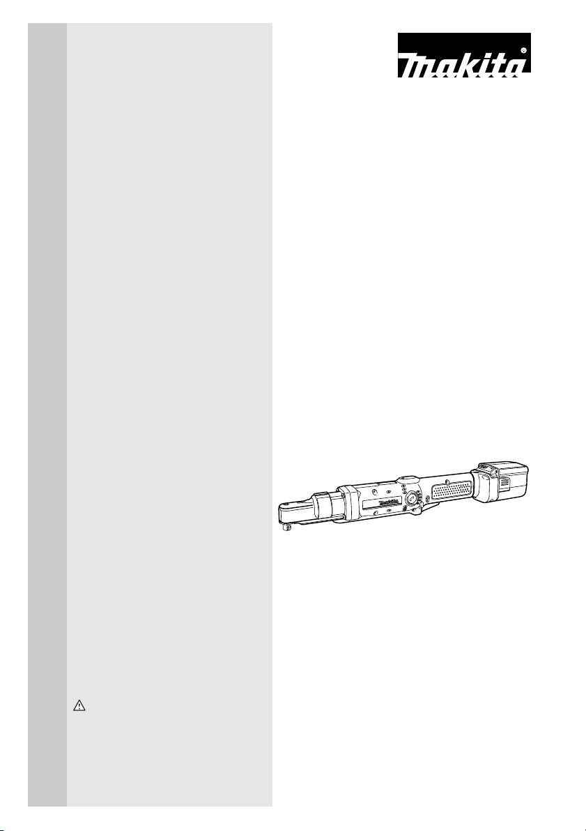
Cordless Angle Nut
Runner
MODEL BFL080F
MODEL BFL081F
MODEL BFL120F
MODEL BFL121F
MODEL BFL200F
INSTRUCTION MANUAL
WARNING:
For your personal safety, READ and UNDERSTAND before using.
SAVE THESE INSTRUCTIONS FOR FUTURE REFERENCE.
003614
Page 2

SPECIFICATIONS
Model BFL080F BFL120F BFL081F BFL121F BFL200F
Hard
Fastening
torque
Square drive 9.5 mm (3/8”) 9.5 mm (3/8”) 9.5 mm (3/8”) 9.5 mm (3/8”) 9.5 mm (3/8”)
No load speed
(RPM)
Dimensions
Net weight
2 - 8 N • m
(17.7 - 70.9 in • lbs)
joint
Soft
2 - 7.5 N • m
(17.7 - 66 in • lbs)
joint
450/min. 250/min. 700/min. 410/min. 220/min.
430 x 65 x 74 mm
(17” x 2-9/16” x 2-15/16”)
(With Battery Cartridge
454 x 65 x 74 mm
(17-7/8” x 2-9/16” x 2-15/16”)
(With Battery Cartridge
1.5 kg (3.3 lbs.) (With Battery
Cartridge BH9020A)
1.7 kg (3.7 lbs.) (With Battery
Cartridge BH9033A)
5 - 12 N • m
(44.3 - 106 in • lbs)
5 - 12 N • m
(44.3 - 106 in • lbs)
BH9020A)
BH9033A)
• Manufacturer reserves the right to change specifications without notice.
• Specifications may differ from country to country.
2 - 8 N • m
(17.7 - 70.9 in • lbs)
2 - 7.5 N • m
(17.7 - 66 in • lbs)
430 x 71 x 92 mm (17” x 2-13/16” x 3-5/8”)
(With Battery Cartridge BH1220)
(With Battery Cartridge BH1220C)
454 x 71 x 92 mm (17-7/8” x 2-13/16” x 3-5/8”)
(With Battery Cartridge BH1233)
(With Battery Cartridge BH1233C)
1.7 kg (3.7 lbs.) (With Battery Cartridge BH1220)
1.6 kg (3.6 lbs.) (With Battery Cartridge BH1220C)
2.0 kg (4.4 lbs.) (With Battery Cartridge BH1233)
1.9 kg (4.2 lbs.) (With Battery Cartridge BH1233C)
5 - 12 N • m
(44.3 - 106 in • lbs)
5 - 11.5 N • m
(44.3 - 102 in • lbs)
413 x 74 x 92 mm
(16-1/4” x 2-15/16” x 3-5/8”)
421 x 74 x 107 mm
(16-5/8”” x 2-15/16” x 4-1/4”)
8 - 20 N • m
(70.9 - 177 in • bs)
8 - 18 N • m
(70.9 - 160 in • bs)
GENERAL SAFETY RULES USA003-1
(FOR All BATTERY OPERATED TOOLS)
WARNING:
Read and understand all instructions. Failure to follow all
instructions listed below, may result in electric shock, fire and/or
serious personal injury.
2
Page 3

SAVE THESE INSTRUCTIONS
Work Are a
1. Keep your work area clean and well lit.
Cluttered benches and dark areas invite accidents.
2. Do not operate power tools in explosive
atmospheres, such as in the presence of
flammable liquids, gases, or dust. Powe r
tools create sparks which may ignite the dust
or fumes.
3. Keep bystanders, children, and visitors
away while operating a power tool. Distrac-
tions can cause you to lose control.
Electrical Safety
4. A battery operated tool with integral batteries or a separate battery pack must be
recharged only with the specified charger
for the battery. A charger that may be suit-
able for one type of battery may create a risk
of fire when used with another battery.
5. Use battery operated tool only with specifically designated battery pack. Use of any
other batteries may create a risk of fire.
Personal Safety
6. Stay alert, watch what you are doing, and
use common sense when operating a
power tool. Do not use tool while tired or
under the influence of drugs, alcohol, or
medication. A moment of inattention while
operating power tools may result in serious
personal injury.
7. Dress properly. Do not wear loose clothing or jewelry. Contain long hair. Keep
your hair, clothing, and gloves away from
moving parts. Loose clothes, jewelry, or long
hair can be caught in moving parts.
8. Avoid accidental starting. Be sure switch
is in the locked or off position before
inserting battery pack. Carrying tools with
your finger on the switch or inserting the battery pack into a tool with the switch on invites
accidents.
9. Remove adjusting keys or wrenches
before turning the tool on. A wrench or a
key that is left attached to a rotating part of
the tool may result in personal injury.
10. Do not overreach. Keep proper footing
and balance at all times. Proper footing and
balance enable better control of the tool in
unexpected situations.
11. Use safety equipment. Always wear eye
protection. Dust mask, non-skid safety
shoes, hard hat, or hearing protection must
be used for appropriate conditions.
Tool Use and Care
12. Use clamps or other practical way to
secure and support the workpiece to a
stable platform. Holding the work by hand or
against your body is unstable and may lead
to loss of control.
13. Do not force tool. Use the correct tool for
your application. The correct tool will do the
job better and safer at the rate for which it is
designed.
14. Do not use tool if switch does not turn it
on or off. A tool that cannot be controlled
with the switch is dangerous and must be
repaired.
15. Disconnect battery pack from tool or
place the switch in the locked or off position before making any adjustments,
changing accessories, or storing the tool.
Such preventive safety measures reduce the
risk of starting the tool accidentally.
16. Store idle tools out of reach of children
and other untrained persons. Tools are
dangerous in the hands of untrained users.
17. When battery pack is not in use, keep it
away from other metal objects like: paper
clips, coins, keys, nails, screws, or other
small metal objects that can make a connection from one terminal to another.
Shorting the battery terminals together may
cause sparks, burns, or a fire.
3
Page 4

18. Maintain tools with care. Keep cutting
tools sharp and clean. Properly maintained
tools with sharp cutting edge are less likely to
bind and are easier to control.
19. Check for misalignment or binding of
moving parts, breakage of parts, and any
other condition that may affect the tool’s
operation. If damaged, have the tool serviced before using. Many accidents are
caused by poorly maintained tools.
20. Use only accessories that are recommended by the manufacturer for your
model. Accessories that may be suitable for
one tool may create a risk of injury when
used on another tool.
SERVICE
21. Tool service must be performed only by
qualified repair personnel. Service or main-
tenance performed by unqualified personnel
may result in a risk of injury.
22. When servicing a tool, use only identical
replacement parts. Follow instructions in
the Maintenance section of this manual.
Use of unauthorized parts or failure to follow
Maintenance instructions may create a risk of
shock or injury.
SPECIFIC SAFETY RULES USB082-1
DO NOT let comfort or familiarity with product (gained from
repeated use) replace strict adherence to cordless Angle Nut
Runner safety rules. If you use this tool unsafely or incorrectly,
you can suffer serious personal injury.
1. Hold tool by insulated gripping surfaces
when performing an operation where the
cutting tool may contact hidden wiring.
Contact with a “live” wire will also make
exposed metal parts of the tool “live” and
shock the operator.
2. Be aware that this tool is always in an
operating condition, because it does not
have to be plugged into an electrical outlet.
3. Always be sure you have a firm footing.
Be sure no one is below when using the
tool in high locations.
4. Hold the tool firmly.
5. Keep hands away from rotating parts.
SAVE THESE INSTRUCTIONS
WARNING:
MISUSE or failure to follow the safety rules stated in this
instruction manual may cause serious personal injury.
4
Page 5

SYMBOLS USD301-1
The followings show the symbols used for tool.
V .......................volts
................... direct current
....................no load speed
n
˚
.../min................revolutions or reciprocation per
minute
IMPORTANT SAFETY INSTRUCTIONS FOR
CHARGER & BATTERY CARTRIDGE
1. SAVE THESE INSTRUCTIONS- This manual contains important safety and operating instructions for battery charger.
2. Before using battery charger, read all
instructions and cautionary markings on
(1) battery charger, (2) battery, and (3)
product using battery.
3. CAUTION - To reduce risk of injury, charge
only MAKITA rechargeable batteries
marked on the charger label. Other types
of batteries may burst causing personal
injury and damage.
4. Do not expose charger to rain or snow.
5. Use of an attachment not recommended
or sold by the battery charger manufacturer may result in a risk of fire, electric
shock, or injury to persons.
Table 1: RECOMMENDED MINIMUM AWG SIZE FOR EXTENSION CORDS FOR BATTERY CHARGERS
6. To reduce risk of damage to electric plug
and cord, pull by plug rather than cord
when disconnecting charger.
7. Make sure cord is located so that it will
not be stepped on, tripped over, or otherwise subjected to damage or stress.
8. An extension cord should not be used
unless absolutely necessary. Use of
improper extension cord could result in a
risk of fire and electric shock. If extension
cord must be used, make sure:
a. That pins on plug of extension cord
are the same number, size, and shape
as those of plug on charger;
b. That extension cord is properly wired
and in good electrical condition; and
c. That wire size is at least as large as
the one specified in the table below.
USC002-3
Length of Cord (Feet) 25 50 100 150
AWG Size of Cord 18 18 18 16
9. Do not operate charger with damaged
cord or plug - replace them immediately.
10. Do not operate charger if it has received a
sharp blow, been dropped, or otherwise
damaged in any way; take it to a qualified
serviceman.
5
Page 6

11. Do not disassemble charger or battery
cartridge; take it to a qualified serviceman
when service or repair is required. Incorrect reassembly may result in a risk of
electric shock or fire.
12. To reduce risk of electric shock, unplug
charger from outlet before attempting any
maintenance or cleaning. Turning off controls will not reduce this risk.
13. The battery charger is not intended for
use by young children or infirm persons
without supervision.
14. Young children should be supervised to
ensure that they do not play with the battery charger.
15. If operating time has become excessively
shorter, stop operating immediately. It
may result in a risk of overheating, possible burns and even an explosion.
16. If electrolyte gets into your eyes, rinse
them out with clear water and seek medical attention right away. It may result in
loss of your eyesight.
ADDITIONAL SAFETY RULES FOR CHARGER &
BATTERY CARTRIDGE
1. Do not charge Battery Cartridge when
temperature is BELOW 10°C (50°F) or
ABOVE 40°C (104°F).
2. Do not attempt to use a step-up transformer, an engine generator or DC power
receptacle.
3. Do not allow anything to cover or clog the
charger vents.
4. Do not short the battery cartridge:
(1) Do not touch the terminals with any
conductive material.
(2) Avoid storing battery cartridge in a
container with other metal objects
such as nails, coins, etc.
(3) Do not expose battery cartridge to
water or rain.
A battery short can cause a large current
flow, overheating, possible burns and
even a breakdown.
5. Do not store the tool and Battery Cartridge in locations where the temperature
may reach or exceed 50°C (122°F).
6. Do not incinerate the Battery Cartridge
even if it is severely damaged or is completely worn out. The battery cartridge can
explode in a fire.
7. Be careful not to drop, shake or strike battery.
8. Do not charge inside a box or container of
any kind. The battery must be placed in a
well ventilated area during charging.
SAVE THESE INSTRUCTIONS
6
Page 7

SYMBOLS
The following show the symbols used for the charger. Be sure that you understand their
meaning before use.
.......... Ready to charge
............. Charging
............. Charging complete
...........Delay charge (Cooling)
........Defective battery
....Conditioning
...........Cooling abnormality
7
Page 8

FUNCTIONAL
DESCRIPTION
1. Battery cartridge
1. Battery cartridge
CAUTION:
• Always be sure that the tool is switched off and the
battery cartridge is removed before adjusting or
checking function on the tool.
003615
Installing or removing battery cartridge
• Always switch off the tool before insertion or removal of
the battery cartridge.
For Models BFL080F, BFL120F
• To remove the battery cartridge, withdraw it from the tool
1
while pressing the buttons on both sides of the cartridge.
• To insert the battery cartridge, align the tongue on the
battery cartridge with the groove in the housing and slip
003616
it into place. Always insert it all the way until it locks in
place with a little click. If not, it may accidentally fall out
of the tool, causing injury to you or someone around you.
For Models BFL081F, BFL121F, BFL200F
• To remove the battery cartridge, withdraw it from the tool
while sliding the button on the front of the cartridge.
1
• To insert the battery cartridge, align the tongue on the
battery cartridge with the groove in the housing and slip
it into place. Always insert it all the way until it locks in
place with a little click. If you can see the red part on the
upper side of the button, it is not locked completely.
Insert it fully until the red part cannot be seen. If not, it
may accidentally fall out of the tool, causing injury to you
or someone around you.
• Do not use force when inserting the battery cartridge. If
the cartridge does not slide in easily, it is not being
inserted correctly.
Charging
Before using battery charger, read all instructions and cautionary markings on the battery charger.
Tips for maintaining maximum battery life
1. Charge the battery cartridge before completely discharged.
Always stop tool operation and charge the battery cartridge when you notice less tool power.
2. Never recharge a fully charged battery cartridge.
Overcharging shortens the battery service life.
8
Page 9

3. Charge the battery cartridge with room temperature at
4. Charge the Nickel Metal Hydride battery cartridge when
5. Always stop tool operation and charge the battery car-
Refresh charging
Refreshing battery adapter (optional accessory) can refresh
an inactive battery cartridge.
• Refresh charging should be done once a week.
• When you charge a new battery cartridge or a battery
001254
Indicating lamp
(C) E F
orange
Indicating lamp
EF
orange
Capacity
80% - 100%
60% - 80%
40% - 60%
10% - 40%
0% - 10%
Capacity
80% - 100%
60% - 80%
40% - 60%
10% - 40%
0% - 10%
Checking the remaining battery capacity
When charging
When the charging begins, the first (far left) indicating lamp
begins to flicker. Then, as charging proceeds, the other lamps
light, one after the other, to indicate the battery capacity.
When using
When the tool is switched on, the lamps will light to indicate
the remaining battery capacity. When the tool is switched off,
the light goes out. If the battery has not been used for a long
time, or is needed refresh charging, the orange lamp begins
to flicker. Use Makita refreshing adapter to refresh the battery.
• A battery cartridge extracted from the charger that has
NOTE:
• Please contact Makita Authorized or Factory Service
10°C - 40°C (50°F - 104°F).
Let a hot battery cartridge cool down before charging it.
you do not use it for more than six months.
tridge when you notice that the warning lamp lightened up.
cartridge that has not been used for a long time, it may
not accept a full charge. In this case, refresh charging
must be done. The battery cartridge may decrease the
tool performance, because the chemical substance of
the battery cartridge is inactive.
CAUTION:
been unplugged with the battery cartridge inserted does
not indicate the battery capacity due to its protective
function even if the tool is switched on after the battery
insertion into the tool. At this time, recharge it for about
five seconds before use.
Center if the warning lamp of the battery cartridge does
not light up when using or charging.
9
Page 10

1
1. Switch trigger
A
1
1. Reversing switch lever
003617
003618
B
Switch action
CAUTION:
• Before inserting the battery cartridge into the tool,
always check to see that the switch trigger actuates
properly and returns to the “OFF” position when
released.
To start the tool, simply pull the switch trigger. Release the
switch trigger to stop.
Reversing switch action
CAUTION:
• Always check the direction of rotation before operation.
• Use the reversing switch only after the tool comes to a
complete stop. Changing the direction of rotation before
the tool stops may damage the tool.
• When not operating the tool, always set the reversing
switch lever to the neutral position.
This tool has a reversing switch to change the direction of
rotation. Depress the reversing switch lever from the A side
for clockwise rotation or from the B side for counterclockwise
rotation.
When the reversing switch lever is in the neutral position, the
switch trigger cannot be pulled.
2
1
1. Light
2. LED indicator
10
003619
Lighting up the lamps
CAUTION:
• Do not look in the light or see the source of light directly.
Pull the switch trigger to light up the lamp. The lamp keeps
on lighting while the switch trigger is being pulled. The light
automatically goes out 10 seconds after the switch trigger is
released.
NOTE:
• Use a dry cloth to wipe the dirt off the lens of lamp. Be
careful not to scratch the lens of lamp, or it may lower the
illumination.
Page 11

LED indicator
The lamp on the tool shows the following functions.
Function Status
Auto-stop fastening This function works when
Delayed re-start For approximately one
Warning against
insufficient fastening
Warning for battery
cartridge capacity
Checking the remaining battery capacity,
Autostop
Check the LED indicator, light and beeper
operation
Anti-reset of controller This function works when
Overheat This function works when
Operation error of the
switch tr igger
the tool has reached the
preset fastening torque
and normal tightening has
been completed. This
helps overtightening to be
avoided.
second after auto-stop fastening, the tool does not
start even if the switch trigger is pulled.
Insufficient fastening has
been performed when the
switch trigger has released
before reaching the preset
fastening torque.
This indicates the appropriate time to replace the
battery cartridge when the
battery power becomes
low.
This function works when
the battery power is almost
used up. At this time, tool
stops immediately.
This function works to
check the proper operation
of the LED indicator, light
and beeper when a battery
cartridge has been
inserted into the tool.
an abnormal drop of the
battery voltage occurs for
some reason, and the tool
stops.
the temperature of the
controller goes up very
highly, and the tool stops.
This function works to
avoid the tool's immediate
start upon insertion of battery cartridge into the tool
with the switch trigger
being pulled.
003814
Status of the LED indicator/beeper
LED indicator Beeper
Lights up in green
for approximately
one second.
--
Lights up in red. A long beep Retighten the screw
Flickers in red
slowly.
Lights up in red. A long beep Replace the battery
Lights up first in
green, next red.
(And then the light
comes on.)
Flickers in red and
green alternatively.
Flickers in red
quickly.
Flickers in red and
green alternatively.
A series of long
beeps
A series of very
short beeps
A series of short
beeps
A series of short
beeps
A series of short
beeps
Action to be taken
Replace the battery
with fully charged one
with fully charged one
-
Replace the battery
with fully charged one
Remove the battery
cartridge immediately
and cool the tool
down.
Release the switch
trigger.
11
Page 12

1
2
3
4
8
1. Angle head
2. Adjusting ring
3. Ring
4. Sclae
5. Adjusting grip
6. Hole for Adjusting grip
7. Yellow line
8. Compression spring
003621
Adjusting the fastening torque
When you wish to drive machine screws, wood screws, hex
bolts, etc. with the predetermined torque, adjusting the fastening torque as follows.
1. First remove the battery cartridge from the tool.
2. Loosen the screws securing the light cover.
3. Rotate the ring in the front of the tool by hand so that a
hole can be seen below the ring.
003622
4. Place the battery cartridge in place and pull the switch
5
trigger. Release it so that the adjusting ring rotates and
becomes visible in the hole. And then remove the battery
cartridge.
6
5. Use an optional adjusting grip to adjust the fastening
torque. Insert the pin of the adjusting grip into the hole in
7
the front of the tool. And then, turn the adjusting grip
clockwise to set a greater fastening torque, and counterclockwise to set a smaller fastening torque.
6. Align the yellow line with your desired number on the fastening torque scale.
7. Insert the battery cartridge and be sure that a fastening
torque has been set up by using a fastening torque
tester.
8. Tighten the screws to secure the light cover and then
rotate the ring in front of the tool until the ring is locked.
NOTE:
• Numbers on the fastening torque scale is a guideline to
set up your desired fastening torque.
ASSEMBLY
12
CAUTION:
• Always be sure that the tool is switched off and the
battery cartridge is removed before carrying out any
work on the tool.
Selecting correct socket
Always use the correct size socket for bolts and nuts. An
incorrect size socket will result in inaccurate and inconsistent
fastening torque and/or damage to the bolt or nut.
Page 13

1
2
3
1. Socket
2. Hole
3. Pin
003623
Installing or removing socket
To install the socket, push it onto the square drive of the tool
with one hand by depressing a pin on the square drive with
another hand until it locks into place. To remove the socket,
simply pull it off depressing the pin on the square drive.
OPERATION
Hold the tool firmly and place the socket over the bolt or nut.
Then switch the tool on. When the clutch cuts in, the motor
will stop automatically. Then release the switch trigger.
NOTE:
• Hold the tool with its square drive pointed straight at the
bolt or nut, or the bolt or nut will be damaged.
Limits of fastening capacity
Use the tool within the limits of fastening capacity. If you use
the tool beyond the limits, the clutch does not work. And the
tool cannot deliver enough fastening torque.
003624
360
300
240
180
120
Revolution angle( )
Range of fastening capacity
60
0
234 5678
Range of fastening capacity
Torque
BFL080F
N.m
005026
BFL081F
Revolution angle ( )
Torque
N.m
13
Page 14

360
300
240
180
120
Revolution angle( )
360
300
240
180
120
Revolution angle( )
360
300
240
180
120
Revolution angle( )
Range of fastening capacity
60
0
567 8
Range of fastening capacity
60
0
567 8
Range of fastening capacity
60
0
81012141618 20
9101112
Torque
9101112
Torque
Torque
003625
BFL120F
N.m
003626
BFL121F
N.m
003627
BFL200F
N.m
14
NOTE:
• The revolution angle means the angle which a screw/bolt
revolves when the tool attains to 100% from 50% of
desired torque.
• Use of a low temperature conditioned battery cartridge
may sometimes give warning for battery cartridge
capacity by warning lamp and beeper which makes the
tool stop immediately. In this case, the range of fastening
capacity may be inferior to those shown in the above
even if a charged battery cartridge is used.
Page 15

MAINTENANCE
1
1. Limit mark
1
2
1. Screwdriver
2. Brush holder cap
CAUTION:
• Always be sure that the tool is switched off and the
battery cartridge is removed before attempting to
perform inspection or maintenance.
001145
Replacing carbon brushes
Remove and check the carbon brushes regularly. Replace
when they wear down to the limit mark. Keep the carbon
brushes clean and free to slip in the holders. Both carbon
brushes should be replaced at the same time. Use only identical carbon brushes.
003628
Use a screwdriver to remove the brush holder caps. Take out
the worn carbon brushes, insert the new ones and secure
the brush holder caps.
To maintain product SAFETY and RELIABILITY, repairs, any
other maintenance or adjustment should be performed by
Makita Authorized or Factory Service Centers, always using
Makita replacement parts.
ACCESSORIES
CAUTION:
• These accessories or attachments are recommended for
use with your Makita tool specified in this manual. The
use of any other accessories or attachments might
present a risk of injury to persons. Only use accessory
or attachment for its stated purpose.
If you need any assistance for more details regarding these
accessories, ask your local Makita service center.
• Battery charger DC14SA
• Ni-MH Battery Cartridge BH9020A/9033A
• Ni-MH Battery Cartridge BH1220/BH1233
• Automatic refreshing adapter
• Protector
• Angle head set
15
Page 16

MAKITA LIMITED ONE YEAR WARRANTY
Warranty Policy
Every Makita tool is thoroughly inspected and tested before leaving the factory. It is warranted to be free of defects from
workmanship and materials for the period of ONE YEAR from the date of original purchase. Should any trouble develop during
this one year period, return the COMPLETE tool, freight prepaid, to one of Makita’s Factory or Authorized Service Centres.
If inspection shows the trouble is caused by defective workmanship or material, Makita will repair (or at our option, replace)
without charge.
This Warranty does not apply:
• where normal maintenance is required,
• repairs have been made or attempted by others,
• the tool has been abused, misused or improperly maintained,
• alterations have been made to the tool.
IN NO EVENT SHALL MAKITA BE LIABLE FOR ANY INDIRECT, INCIDENTAL OR CONSEQUENTIAL DAMAGES FROM
THE SALE OR USE OF THE PRODUCT. THIS DISCLAIMER APPLIES BOTH DURING AND AFTER THE TERM OF THIS
WARRANTY.
“The Makita Warranty is the only and the entire written warranty given by Makita for the Makita tools. No dealer or his agent
or employee is authorized to extend or enlarge upon this warranty by any verbal or written statement or advertisement.”
MAKITA DISCLAIMS LIABILITY FOR ANY IMPLIED WARRANTIES INCLUDING IMPLIED WARRANTIES OF
“MERCHANTABILITY” AND FITNESS FOR A SPECIFIC PURPOSE,” AFTER THE ONE YEAR TERM OF THIS WARRANTY.
“This Warranty gives you specific rights. The provisions contained in this warranty are not intended to limit, modify, take away
from, disclaim or exclude any warranties set forth in any provincial legislation. To the extent required by law, the provisions in
any provincial or federal legislation with respect to warranties take precedence over the provisions in this warranty.”
884456G231
Makita Corporation
3-11-8, Sumiyoshi-cho,
Anjo, Aichi 446-8502 Japan
 Loading...