

Page 1

INSTRUCTION MANUAL
MANUEL D'INSTRUCTION
MANUAL DE INSTRUCCIONES
Hazardous Location Cordless Driver
Tournevis sans fil pour endroits
dangereux
Destornillador inalámbrico para
lugares peligrosos
BFH040
BFH040F
BFH090
BFH090F
BFH120F
004039
WARNING:
For your personal safety, READ and UNDERSTAND before using.
SAVE THESE INSTRUCTIONS FOR FUTURE REFERENCE.
AVERTISSEMENT:
Pour votre propre sécurité, prière de lire attentivement avant l’utilisation.
GARDER CES INSTRUCTIONS POUR RÉFÉRENCE ULTÉRIEURE.
ADVERTENCIA:
Para su seguridad personal, LEA DETENIDAMENTE este manual antes de usar la herramienta.
GUARDE ESTAS INSTRUCCIONES PARA FUTURA REFERENCIA.
Page 2

ENGLISH
SPECIFICATIONS
Model BFH040/BFH040F BFH090/BFH090F BFH120F
Fastening torque 0.8-4.5 N•m (7-40 in.•lbs) 3.4-9 N•m (30-80 in•lbs) 5-12 N•m (44-106 in•lbs)
No load speed (RPM) 400/min
Dimensions
Net weight 1.5 kg (3.3 lbs) (with Battery Cartridge BH1220)
Rated voltage D.C. 12 V
Hazardous Location Rating Class I Division 2 Rated for max 50°C ambient
• Due to our continuing programme of research and development, the specifications herein are subject to change
without notice.
• Note: Specifications may differ from country to country.
190 mm x 266 mm x 71 mm (7-15/32” x 10-15/32” x 2-13/16”)
(with Battery Cartridge BH1220)
GENERAL SAFETY RULES
USA015-1
(FOR ALL BATTERY OPERATED TOOLS)
WARNING:
Read and understand all instructions.
Failure to follow all instructions listed below,
may result in electric shock, fire and/or
serious personal injury.
SAVE THESE INSTRUCTIONS
Work Area
1. Keep your work area clean and well lit. Cluttered
benches and dark areas invite accidents.
2. Keep bystanders, children, and visitors away
while operating a power tool. Distractions can
cause you to lose control.
Electrical Safety
3. A battery operated tool with integral batteries or
a separate battery pack must be recharged only
with the specified charger for the battery. A
charger that may be suitable for one type of battery
may create a risk of fire when used with another battery.
4. Use battery operated tool only with specifically
designated battery pack. Use of any other batter-
ies may create a risk of fire.
Personal Safety
5. Stay alert, watch what you are doing, and use
common sense when operating a power tool. Do
not use tool while tired or under the influence of
drugs, alcohol, or medication. A moment of inat-
tention while operating power tools may result in
serious personal injury.
6. Dress properly. Do not wear loose clothing or
jewelry. Contain long hair. Keep your hair, clothing, and gloves away from moving parts. Loose
clothes, jewelry, or long hair can be caught in moving parts.
7. Avoid accidental starting. Carrying tools with your
finger on the switch invites accidents.
8. Remove adjusting keys or wrenches before turning the tool on. A wrench or a key that is left
attached to a rotating part of the tool may result in
personal injury.
9. Do not overreach. Keep proper footing and balance at all times. Proper footing and balance
enable better control of the tool in unexpected situations.
10. Use safety equipment. Always wear eye protection. Dust mask, non-skid safety shoes, hard hat, or
hearing protection must be used for appropriate conditions.
Tool Use and Care
11. Use clamps or other practical way to secure and
support the workpiece to a stable platform. Hold-
ing the work by hand or against your body is unstable and may lead to loss of control.
12. Do not force tool. Use the correct tool for your
application. The correct tool will do the job better
and safer at the rate for which it is designed.
13. Do not use tool if switch does not turn it on or
off. A tool that cannot be controlled with the switch is
dangerous and must be repaired.
14. Disconnect battery pack from tool or place the
switch in the locked or off position before making any adjustments, changing accessories, or
storing the tool. Such preventive safety measures
reduce the risk of starting the tool accidentally.
2
Page 3

15. Store idle tools out of reach of children and
other untrained persons. Tools are dangerous in
the hands of untrained users.
16. When battery pack is not in use, keep it away
from other metal objects like: paper clips, coins,
keys, nails, screws, or other small metal objects
that can make a connection from one terminal to
another. Shorting the battery terminals together
may cause sparks, burns, or a fire.
17. Check for misalignment or binding of moving
parts, breakage of parts, and any other condition
that may affect the tool’s operation. If damaged,
have the tool serviced before using. Many acci-
dents are caused by poorly maintained tools.
18. Use only accessories that are recommended by
the manufacturer for your model. Accessories
that may be suitable for one tool may create a risk of
injury when used on another tool.
Service
19. Tool service must be performed only by qualified
repair personnel. Service or maintenance per-
formed by unqualified personnel may result in a risk
of injury.
20. When servicing a tool, use only identical
replacement parts. Follow instructions in the
Maintenance section of this manual. Use of unau-
thorized parts or failure to follow Maintenance
instructions may create a risk of shock or injury.
SPECIFIC SAFETY RULES
USB081-3
DO NOT let comfort or familiarity with
product (gained from repeated use)
replace strict adherence to cordless
screwdriver safety rules. If you use this
tool unsafely or incorrectly, you can suffer serious personal injury.
1. Hold tool by insulated gripping surfaces when
performing an operation where the cutting tool
may contact hidden wiring. Contact with a “live”
wire will also make exposed metal parts of the tool
“live” and shock the operator.
2. Be aware that this tool is always in an operating
condition, because it does not have to be
plugged into an electrical outlet.
3. Always be sure you have a firm footing.
Be sure no one is below when using the tool in
high locations.
4. Hold the tool firmly.
5. Keep hands away from rotating parts.
Cordless Hazardous Location Screwdriver
INSTRUCTION MANUAL
IMPORTANT SAFETY INSTRUCTIONS
FOR OPERATING THIS POWER TOOL IN
HAZARDOUS LOCATIONS
Underwriters Laboratories Inc (UL) listed for the following: UL 1604 Class I Division 2 Group A~D Hazardous (Classified) Locations defined by National
Electrical Code (NEC).
• Class I Division 2 : where ignitable concentrations of flammable gases, vapors or liquids are
not likely to exist under normal operating conditions.
• Group A: atmosphere such as “acetylene” ,
gases or vapor of equivalent hazard
• Group B: atmosphere such as “hydrogen” ,
gases or vapor of equivalent hazard
• Group C: atmosphere such as “ethylene” , gases
or vapor of equivalent hazard
• Group D: atmosphere such as “propane” , gases
or vapor of equivalent hazard
THIS EQUIPMENT IS SUITABLE FOR USE IN CLASS
I, DIVISION 2, GROUPS A, B, C AND D OR NON-HAZARDOUS LOCATIONS ONLY.
DANGER:
This tool should only be used as a
screwdriver. The use of this tool in any
other way may result in the ignition of a
flammable atmosphere.
WARNING:
EXPLOSION HAZARD - SUBSTITUTION
OF COMPONENTS MAY IMPAIR
SUITABILITY FOR CLASS I, DIVISION 2.
Battery Charger DC14SA is not in
compliance with stated listings (UL1604).
The use of the battery charger in a
Hazardous Location may result in the
ignition of a flammable atmosphere and
result in serious injury to the user.
Do not operate the charger in explosive
atmospheres, such as in the presence of
flammable liquids, gases or dust.
Chargers create sparks which may ignite
the dust or fumes.
3
Page 4
SAVE THESE INSTRUCTIONS
WARNING:
MISUSE or failure to follow the safety
rules stated in this instruction manual
may cause serious personal injury.
SYMBOLS
The followings show the symbols used for tool.
V............................volts
........................direct current
.........................no load speed
.../min....................revolutions or reciprocation per
minute
USD301-1
IMPORTANT SAFETY
INSTRUCTIONS FOR BATTERY
CARTRIDGE
1. Before using battery cartridge, read all instructions and cautionary markings on (1) battery
charger, (2) battery, and (3) product using battery.
2. Do not disassemble battery cartridge.
3. If operating time has become excessively
shorter, stop operating immediately. It may
result in a risk of overheating, possible burns
and even an explosion.
4. If electrolyte gets into your eyes, rinse them out
with clear water and seek medical attention right
away. It may result in loss of your eyesight.
5. Do not short the battery cartridge:
(1) Do not touch the terminals with any conduc-
tive material.
(2) Avoid storing battery cartridge in a con-
tainer with other metal objects such as nails,
coins, etc.
(3) Do not expose battery cartridge to water or
rain.
A battery short can cause a large current flow,
overheating, possible burns and even a breakdown.
6. Do not store the tool and battery cartridge in
locations where the temperature may reach or
exceed 50°C (122°F).
7. Do not incinerate the battery cartridge even if it
is severely damaged or is completely worn out.
The battery cartridge can explode in a fire.
ENC005-1
8. Be careful not to drop or strike battery.
SAVE THESE INSTRUCTIONS
Tips for maintaining maximum battery
life
1. Charge the battery cartridge before completely
discharged.
Always stop tool operation and charge the battery cartridge when you notice less tool power.
2. Never recharge a fully charged battery cartridge.
Overcharging shortens the battery service life.
3. Charge the battery cartridge with room temperature at 10°C - 40°C (50°F - 104°F). Let a hot battery cartridge cool down before charging it.
4. Charge the Nickel Metal Hydride battery cartridge when you do not use it for more than six
months.
FUNCTIONAL DESCRIPTION
CAUTION:
• Always be sure that the tool is switched off and the
battery cartridge is removed before adjusting or
checking function on the tool.
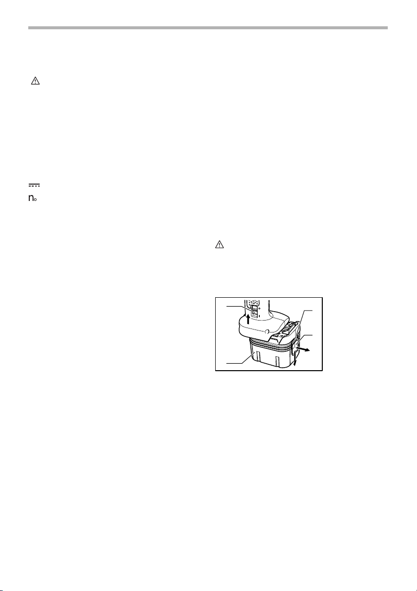
Installing or removing battery cartridge
1
2
• Always switch off the tool before insertion or
removal of the battery cartridge.
• To remove the battery cartridge, raise the interlock
switch and withdraw it from the tool while sliding the
button on the front of the cartridge. (Note: Battery
cartridge cannot be removed without raising the
interlock switch.)
• To insert the battery cartridge, align the tongue on
the battery cartridge with the groove in the housing
and slip it into place. Always insert it all the way
until it locks in place with a little click. If you can see
the red part on the upper side of the button, it is not
locked completely. Insert it fully until the red part
cannot be seen. If not, it may accidentally fall out of
the tool, causing injury to you or someone around
you.
• Lower the interlock switch after insertion of battery
cartridge. Even if the switch trigger is pulled with
the interlock switch raised, the tool does not start.
004040
1. Interlock switch
2. Battery car-
3
3. Red part
4
4. Button
tridge
4
Page 5

(Note: The battery cartridge can be inserted even
while the interlock switch is lowered. Once the
battery cartridge is inserted, the interlock switch will
rise automatically.)
• Do not use force when inserting the battery
cartridge. If the cartridge does not slide in easily, it
is not being inserted correctly.
Switch action
004041
1. Switch trigger
side for clockwise rotation or from the B side for counterclockwise rotation.
When the reversing switch lever is in the neutral position,
the switch trigger cannot be pulled.
Lighting up the front lamp
For models BFH040F/BFH090F/BFH120F only
004043
1. Front lamp
1
CAUTION:
• Before inserting the battery cartridge into the tool,
always check to see that the switch trigger actuates
properly and returns to the “OFF” position when
released.
To start the tool, simply pull the switch trigger. Release
the switch trigger to stop.
Automatic power off
When the switch trigger is kept being pulled for three
minutes without driving screws or tightening bolts, the
tool automatically stops. To restart the tool, release the
switch trigger and then pull it again.
Reversing switch action
A
CAUTION:
• Always check the direction of rotation before
operation.
• Use the reversing switch only after the tool comes
to a complete stop. Changing the direction of
rotation before the tool stops may damage the tool.
• When not operating the tool, always set the
reversing switch lever to the neutral position.
This tool has a reversing switch to change the direction of
rotation. Depress the reversing switch lever from the A
1
004042
1. Reversing
switch lever
B
1
CAUTION:
• Do not look in the light or see the source of light
directly.
Pull the switch trigger to light up the lamp. The lamp
keeps on lighting while the switch trigger is being pulled.
The light automatically goes out 10 seconds after the
switch trigger is released.
NOTE:
• Use a dry cloth to wipe the dirt off the lens of lamp.
Be careful not to scratch the lens of lamp, or it may
lower the illumination.
LED indicator
004044
1. LED indicator
1
LED indicator on the tool shows the following functions.
Beeper
For models BFH040F/BFH090F/BFH120F only
Also, Beeper on the tool shows the following functions.
5
Page 6

The LED indicator/beeper on the tool shows the following functions.
Function Status
Auto-stop
fastening
Delayed re-start
Warning against
insufficient
fastening
Warning for
battery cartridge
capacity
Checking the
remaining
battery capacity,
auto-stop
Operation error
of the removing
battery cartridge
Check the LED
indicator, front
lamp and
beeper
operation
Anti-reset of
controller
Overheat
Motor
malfunction
Interlock switch
malfunction
* For models BFH040F/BFH090F/BFH120F only
This function works when the tool has
reached the preset fastening torque and
normal tightening has been completed.
This helps overtightening to be avoided.
For approximately one second after
auto-stop fastening, the tool does not
start even if the switch trigger is pulled.
Insufficient fastening has been
performed when the switch trigger has
released before reaching the preset
fastening torque.
This indicates the appropriate time to
replace the battery cartridge when the
battery power becomes low.
This function works when the battery
power is almost used up. At this time,
tool stops immediately.
This function operates to indicate that
an incorrect battery removal operation
is being attempted.
This function works to check the proper
operation of the LED indicator, front
lamp and beeper when a battery
cartridge has been inserted into the tool
and the interlock switch is lowered.
This function works when an abnormal
drop of the battery voltage occurs for
some reason, and the tool stops.
This function works if the temperature of
the controller or moror increases to a
high level and the tool stops.
This indicates the abnormal condition of
the motor. The tool does not operate.
This indicates abnormality of interlock
switch when the battery cartridge has
been inserted. The tool does not
function.
LED indicator/beeper
Status of the LED indicator/beeper
LED indicator Beeper *
Lights up in
green for
approximately
one second.
Lights up in red. A long beep
Flickers in red
slowly.
Lights up in red. A long beep
Flickers in green
slowly.
Light up first in
green, next red
(And then the
front lamp
comes on.*)
Flickers in red
and green
alternatively.
Flickers in red
quickly.
Flickers in red
and green
alternatively.
Flickers in red
and green
alternatively.
--
A series of long
beeps
A series of long
beeps.
A series of very
short beeps
A series of short
beeps
A series of short
beeps
A series of short
beeps
A series of short
beeps
006395
Action to be taken
Retighten the
screw
Replace the
battery with fully
charged one
Replace the
battery with fully
charged one
Release the
switch trigger,
raise the interlock
switch,and then
remove battery
cartridge.
-
Replace the
battery with fully
charged one
Remove the
battery cartridge
immediately and
cool the tool
down.
Ask Makita
service centers.
Ask Makita
service centers.
6
Page 7
Adjusting the fastening torque
When you wish to drive machine screws, wood screws,
hex bolts, etc. with the predetermined torque, adjusting
the fastening torque as follows.
1. First remove the battery cartridge from the tool.
2. Loosen and remove the screw that secures ring.
3. Rotate the ring in the front of the tool by hand so
that a hole can be seen below the ring.
4. Place the battery cartridge in place and pull the
switch trigger. Release it so that the adjusting ring
rotates and becomes visible in the hole. And then
remove the battery cartridge.
5. Use an optional adjusting grip to adjust the fasten-
ing torque. Insert the pin of the adjusting grip into
the hole in the front of the tool. And then, turn the
adjusting grip clockwise to set a greater fastening
torque, and counterclockwise to set a smaller fastening torque.
1
2
3
6. Align the yellow line with your desired number on
the fastening torque scale.
7. Insert the battery cartridge and be sure that a fas-
tening torque has been set up by using a fastening
torque tester.
8. Rotate the ring so that the hole for adjusting grip is
covered, hold and then secure the ring with screw.
NOTE:
• Numbers on the fastening torque scale is a
guideline to set up your desired fastening torque.
3
004045
1
2
004046
4
5
6
7
1. Adjusting ring
2. Ring
1. Adjusting ring
2. Ring
3. Scale
4. Adjusting grip
5. Hole for adjusting grip
6. Yellow line
7. Compression
spring
ASSEMBLY
CAUTION:
• Always be sure that the tool is switched off and the
battery cartridge is removed before carrying out
any work on the tool.
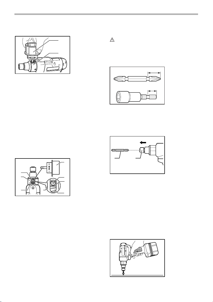
Installing or removing driver bit or socket bit
12mm(15/32")
9mm(3/8")
Use only the driver bit or socket bit shown in the figure.
Do not use any other driver bit or socket bit.
To install the bit, pull the sleeve in the direction of the
arrow and insert the bit into the sleeve as far as it will go.
Then release the sleeve to secure the bit.
1
To remove the bit, pull the sleeve in the direction of the
arrow and pull the bit out firmly.
NOTE:
• If the bit is not inserted deep enough into the
2
sleeve, the sleeve will not return to its original
position and the bit will not be secured. In this case,
try re-inserting the bit according to the instructions
above.
001761
004047
1. Bit
2. Sleeve
OPERATION
Screwdriving operation
004048
7
Page 8

Place the point of the driver bit in the screw head and
apply pressure to the tool. Then switch the tool on. When
the clutch cuts in, the motor will stop automatically. Then
release the switch trigger.
NOTE:
• Make sure that the driver bit is inserted straight in
the screw head, or the screw and/or bit may be
damaged.
MAINTENANCE
CAUTION:
• Always be sure that the tool is switched off and the
battery cartridge is removed before attempting to
perform inspection or maintenance.
To maintain product SAFETY and RELIABILITY, repairs,
any other maintenance or adjustment should be performed by Makita Authorized or Service Centers, always
using Makita replacement parts.
ACCESSORIES
CAUTION:
• These accessories or attachments are
recommended for use with your Makita tool
specified in this manual. The use of any other
accessories or attachments might present a risk of
injury to persons. Only use accessory or
attachment for its stated purpose.
If you need any assistance for more details regarding
these accessories, ask your local Makita Service Center.
• Automatic refreshing adapter
• Adjusting grip
• Various type of Makita genuine batteries and
chargers
MAKITA LIMITED ONE YEAR WARRANTY
EN0006-1
Warranty Policy
Every Makita tool is thoroughly inspected and tested
before leaving the factory. It is warranted to be free of
defects from workmanship and materials for the period of
ONE YEAR from the date of original purchase. Should
any trouble develop during this one year period, return
the COMPLETE tool, freight prepaid, to one of Makita’s
Factory or Authorized Service Centers. If inspection
shows the trouble is caused by defective workmanship or
material, Makita will repair (or at our option, replace)
without charge.
This Warranty does not apply where:
• repairs have been made or attempted by others:
• repairs are required because of normal wear and
tear:
• the tool has been abused, misused or improperly
maintained:
• alterations have been made to the tool.
IN NO EVENT SHALL MAKITA BE LIABLE FOR ANY
INDIRECT, INCIDENTAL OR CONSEQUENTIAL DAMAGES FROM THE SALE OR USE OF THE PRODUCT.
THIS DISCLAIMER APPLIES BOTH DURING AND
AFTER THE TERM OF THIS WARRANTY.
MAKITA DISCLAIMS LIABILITY FOR ANY IMPLIED
WARRANTIES, INCLUDING IMPLIED WARRANTIES
OF “MERCHANTABILITY” AND “FITNESS FOR A SPECIFIC PURPOSE,” AFTER THE ONE YEAR TERM OF
THIS WARRANTY.
This Warranty gives you specific legal rights, and you
may also have other rights which vary from state to state.
Some states do not allow the exclusion or limitation of
incidental or consequential damages, so the above limitation or exclusion may not apply to you. Some states do
not allow limitation on how long an implied warranty lasts,
so the above limitation may not apply to you.
8
Page 9

FRANÇAIS
SPÉCIFICATIONS
Modèle BFH040/BFH040F BFH090/BFH090F BFH120F
Couple de serrage 0.8-4.5 N•m (7-40 in.•lbs) 3.4-9 N•m (30-80 in•lbs) 5-12 N•m (44-106 in•lbs)
Vitesse à vide (T/MIN) 400/min
Dimensions
Poids net 1.5 kg (3.3 lbs) (avec la batterie BH1220)
Tension nominale C.C.12 V
Catégories d’endroits dangereux Classé Classe 1 Division 2 pour une température ambiante maximale de 50°C
• Le fabricant se réserve le droit de modifier sans avertissement les spécifications.
• Note: Les spécifications peuvent varier selon les pays.
190 mm x 266 mm x 71 mm (7-15/32” x 10-15/32” x 2-13/16”)
(avec la batterie BH1220)
CONSIGNES DE SÉCURITÉ
GÉNÉRALES
USA015-1
(POUR TOUS LES OUTILS ALIMENTÉS
PAR BATTERIE)
AVERTISSEMENT:
Assurez-vous d’avoir lu et compris
toutes les instructions. Il y a risque de
choc électrique, d’incendie et/ou de
blessure grave si les instructions ci-dessous
ne sont pas respectées.
CONSERVEZ CES
INSTRUCTIONS
Aire de travail
1. Maintenez votre aire de travail propre et bien
éclairée. Les établis encombrés et les aires de
travail sombres ouvrent la porte aux accidents.
2. Assurez-vous qu’aucun passant, enfant ou
visiteur ne s’approche pendant que vous utilisez
l’outil. Toute distraction risquerait de causer une
perte de contrôle de l’outil.
Sécurité en matière d’électricité
3. Les outils alimentés par une batterie intégrée ou
séparée doivent toujours être rechargés au
moyen du chargeur spécifié pour la batterie en
question. L’utilisation d’un chargeur conçu pour un
type différent de batterie comporte un risque
d’incendie.
4. Un outil alimenté par batterie doit être utilisé
exclusivement avec le bloc-pile conçu
spécifiquement pour cet outil. L’utilisation de toute
autre batterie comporte un risque d’incendie.
Sécurité personnelle
5. Restez alerte, attentif à vos gestes, et faites
preuve de bon sens lorsque vous utilisez un
outil électrique. Évitez d’utiliser l’outil lorsque
vous êtes fatigué ou sous l’influence de
drogues, d’alcool ou de médicaments. Tout
moment d’inattention pendant l’utilisation d’un outil
électrique comporte un risque de blessure grave.
6. Portez des vêtements adéquats. Évitez de porter
des vêtements amples et des bijoux. Portez un
filet de protection pour envelopper vos cheveux
s’ils sont longs. Assurez-vous que vos cheveux,
vêtements et gants demeurent à l’écart des
pièces en mouvement. Les vêtements amples,
bijoux et cheveux longs risquent d’être happés par
les pièces en mouvement.
7. Prévenez tout démarrage accidentel. Le transport
des outils en les tenant avec un doigt sur la gâchette
augmente considérablement les risques d’accident.
8. Retirez les clés de réglage et autres clés avant
de mettre l’outil sous tension. Toute clé laissée en
place sur une pièce rotative peut causer une
blessure.
9. Maintenez une bonne position. Assurez-vous
d’une bonne prise au sol et d’une bonne position
d’équilibre en tout temps. Une bonne prise au sol
et une bonne position d’équilibre assureront un
meilleur contrôle de l’outil dans les situations
imprévues.
10. Utilisez des dispositifs de sécurité. Portez
toujours des lunettes de protection. Suivant les
conditions dans lesquelles vous effectuez votre
travail, vous devez porter un masque
antipoussières, des chaussures à semelle
antidérapante, une coiffure résistante ou une
protection d’oreilles.
9
Page 10

Utilisation et entretien des outils
11. Utilisez un dispositif de serrage ou tout autre
moyen pratique pour fixer la pièce à une surface
de travail stable. La pièce sera instable et vous
risquez de perdre le contrôle de l’outil si vous tenez
la pièce avec la main ou l’appuyez simplement
contre votre corps.
12. Ne forcez pas l’outil. Utilisez un outil qui
convient au travail à effectuer. Si vous utilisez le
bon outil et respectez le régime pour lequel il a été
conçu, il effectuera un travail de meilleure qualité et
de façon plus sûre.
13. N’utilisez pas l’outil si sa gâchette ne peut pas
être activée et désactivée. Un outil dont
l’interrupteur ne fonctionne pas est dangereux et
doit être réparé.
14. Retirez le bloc-pile de l’outil ou placez
l’interrupteur en position de verrouillage ou
d’arrêt avant d’effectuer tout réglage, de changer
d’accessoire ou de ranger l’outil. De telles
mesures préventives réduisent les risques de
démarrage accidentel de l’outil.
15. Une fois l’utilisation de l’outil terminée, rangez-le
hors de portée des enfants et personnes qui en
ignorent le fonctionnement. Les outils
représentent un danger entre les mains de
personnes qui n’en connaissent pas le mode
d’utilisation.
16. Lorsque vous n’utilisez pas le bloc-pile, rangezle à l’écart des objets tels que les trombones,
pièces de monnaie, clés, clous, vis et autres
petits objets métalliques qui risquent d’établir la
connexion entre les bornes. Il y a risque
d’étincelles, de brûlures et d’incendie si les bornes
de la batterie sont court-circuitées.
17. Assurez-vous que les pièces mobiles ne sont
pas désalignées ou coincées, qu’aucune pièce
n’est cassée et que l’outil n’a subi aucun
dommage affectant son bon fonctionnement. Le
cas échéant, faites réparer l’outil avant de
l’utiliser. De nombreux accidents sont causés par
des outils mal entretenus.
18. Utilisez uniquement les accessoires
recommandés par le fabricant pour le modèle
utilisé. Des accessoires qui conviennent à un outil
donné peuvent comporter un risque de blessure
lorsque utilisés sur un autre outil.
Service
19. La réparation doit être confiée uniquement à un
personnel qualifié. Tout e réparation ou entretien
exécuté par un personnel non qualifié peut
comporter un risque de blessure.
20. Seules des pièces de rechange identiques aux
pièces originales doivent être utilisées lors de la
réparation d’un outil. Suivez les instructions de
la section Entretien du présent manuel.
L’utilisation de pièces non spécifiées ou l’ignorance
des instructions d’entretien comporte un risque de
choc électrique ou de blessure.
CONSIGNES DE SÉCURITÉ
SPÉCIFIQUES
USB081-3
NE vous laissez PAS tromper (au fil d’une
utilisation répétée) par un sentiment
d’aisance et de familiarité avec le
produit, en négligeant le respect
rigoureux des consignes de sécurité qui
accompagnent le tournevis sans fil. Si
vous n’utilisez pas cet outil de façon
sûre et adéquate, vous courez un risque
de blessure grave.
1. Saisissez l’outil par ses surfaces de poigne
isolées lorsque vous effectuez une opération au
cours de laquelle l’outil tranchant peut entrer en
contact avec des fils cachés. Le contact avec un
câble sous tension mettra également les parties
métalliques exposées de l’outil sous tension, avec
un risque de choc électrique pour l’utilisateur.
2. Soyez bien conscient du fait que l’outil est
toujours en état de fonctionner puisqu’il n’a pas
à être branché sur une prise de courant.
3. Assurez-vous toujours d’une bonne position
d’équilibre.
Assurez-vous que personne ne se trouve
dessous lorsque vous utilisez l’outil en position
élevée.
4. Tenez l’outil fermement.
5. Gardez les mains éloignées des pièces en
rotation.
Tournevis sans fil pour endroits
dangereux
MANUEL D’INSTRUCTIONS
IMPORTANTES CONSIGNES DE
SÉCURITÉ POUR L’UTILISATION DE CET
OUTIL ÉLECTRIQUE DANS LES
ENDROITS DANGEREUX
Listé comme suit par Underwriters Laboratoires Inc
(UL) : UL 1604 Classe 1 Division 2, Endroits
(classifiés) dangereux, Groupes A à D, tels que
définis par le National Electric Code (NEC).
• Classe 1 Division 2 : endroits exempts, dans des
conditions de fonctionnement normal, de gaz,
vapeurs ou liquides inflammables dans une
concentration telle qu’ils risquent de
s’enflammer.
10
Page 11

• Groupe A : atmosphère composée d’acétylène
ou de gaz ou vapeurs présentant un danger
équivalent
• Groupe B : atmosphère composée d’hydrogène
ou de gaz ou vapeurs présentant un danger
équivalent
• Groupe C : atmosphère composée d’éthylène ou
de gaz ou vapeurs présentant un danger
équivalent
• Groupe D : atmosphère composée de propane
ou de gaz ou vapeurs présentant un danger
équivalent
CET APPAREIL EST APPROPRIÉ UNIQUEMENT
POUR L’UTILISATION DANS LES ENDROITS DE
CLASSE 1, DIVISION 2, GROUPES A, B, C ET D, OU
DANS LES ENDROITS SANS DANGER.
DANGER:
Cet outil ne doit être utilisé qu’en tant
que tournevis. Une atmosphère
inflammable risque de s’enflammer si
l’outil est utilisé de toute autre manière.
MISE EN GARDE:
RISQUE D’EXPLOSION - LE
REMPLACEMENT DES PIÈCES PEUT
ANNULER L’ADÉQUATION À LA CLASSE
1, DIVISION 2.
Le chargeur de batterie DC14SA n’est
pas conforme à la classification
susmentionnée (UL1604).
Une atmosphère inflammable peut
s’enflammer et blesser gravement
l’utilisateur si le chargeur de batterie est
utilisé dans un endroit dangereux.
N’utilisez pas le chargeur dans les
atmosphères explosives, par exemple en
présence de liquides, gaz ou poussières
inflammables. Les chargeurs produisent
des étincelles au contact desquelles la
poussière ou les vapeurs peuvent
s’enflammer.
CONSERVEZ CES
INSTRUCTIONS
AVERTISSEMENT:
LA MAUVAISE UTILISATION de l’outil ou
l’ignorance des consignes de sécurité du
présent manuel d’instructions peuvent
entraîner une grave blessure.
SYMBOLES
Les symboles utilisés pour l’outil sont présentés cidessous.
V ...........................volts
.......................courant alternatif ou continu
.........................vitesse à vide
.../min ...................tours ou alternances par minute
USD301-1
CONSIGNES DE SÉCURITÉ
IMPORTANTES POUR LA
BATTERIE
1. Avant d’utiliser la batterie, lisez toutes les
instructions et précautions relatives (1) au
chargeur de batterie, (2) à la batterie, et (3) à
l’outil utilisant la batterie.
2. Ne démontez pas la batterie.
3. Cessez immédiatement l’utilisation si le temps
de fonctionnement devient excessivement court.
Il y a risque de surchauffe, de brûlures, voire
d’explosion.
4. Si l’électrolyte pénètre dans vos yeux, rincez-les
à l’eau claire et consultez immédiatement un
médecin. Il y a risque de perte de la vue.
5. Ne court-circuitez pas la batterie :
(1) Ne touchez les bornes avec aucun matériau
conducteur.
(2) Évitez de ranger la batterie dans un
conteneur avec d’autres objets métalliques,
par exemple des clous, des pièces de
monnaie, etc.
(3) N’exposez pas la batterie à l’eau ou à la
pluie.
Un court-circuit de la batterie pourrait provoquer
un fort courant, une surchauffe, parfois des
blessures et même une panne.
6. Ne rangez pas l’outil ou la batterie dans des
endroits où la température risque d’atteindre ou
de dépasser 50°C (122°F).
11
ENC005-1
Page 12

7. Ne jetez pas la batterie même si elle est
sérieusement endommagée ou complètement
épuisée. La batterie peut exploser au contact du
feu.
8. Prenez garde d’échapper ou de heurter la
batterie.
CONSERVEZ CES
INSTRUCTIONS
Conseils pour obtenir la durée de
service maximale de la batterie
1. Rechargez la batterie avant qu’elle ne soit
complètement déchargée.
Arrêtez toujours l’outil et rechargez la batterie
quand vous remarquez que la puissance de
l’outil diminue.
2. Ne rechargez jamais une batterie complètement
chargée.
Une surcharge réduira la durée de service de la
batterie.
3. Rechargez la batterie à une température
ambiante comprise entre 10°C et 40°C. (50°F 104°F). Si la batterie est chaude, laissez-la
refroidir avant de la recharger.
4. Rechargez la batterie à hydrure métallique de
nickel lorsqu’elle reste inutilisée pour plus de six
mois.
DESCRIPTION DU
FONCTIONNEMENT
ATTENTION:
• Assurez-vous toujours que l’outil est hors tension et
que sa batterie est retirée avant de l’ajuster ou de
vérifier son fonctionnement.
Installation ou retrait de la batterie
1
2
004040
3
4
1. Interrupteur
d’interverrouillage
2. Batterie
3. Partie rouge
4. Bouton
batterie sans soulever l’interrupteur
d’interverrouillage.)
• Pour insérer la batterie, alignez sa languette sur
l’entaille qui se trouve à l’intérieur du carter, puis
glissez la batterie pour la mettre en place. Insérezla toujours bien à fond, jusqu’à ce qu’elle se
verrouille en émettant un léger clic. Si vous pouvez
voir la partie rouge de la face supérieure du bouton,
la batterie n’est pas parfaitement verrouillée.
Insérez-la à fond, jusqu’à ce que la partie rouge ne
soit plus visible. Sinon, elle risque de tomber
accidentellement de l’outil, en vous blessant ou en
blessant une personne se trouvant près de vous.
• Une fois la batterie insérée, abaissez l’interrupteur
d’interverrouillage. Lorsque l’interrupteur
d’interverrouillage est soulevé, l’outil ne démarre
pas même si vous tirez sur la gâchette. (Note : Il est
possible d’insérer la batterie même lorsque
l’interrupteur d’interverrouillage est abaissé. Ce
dernier se soulève automatiquement après
l’insertion de la batterie.)
• N’appliquez pas une force excessive lors de
l’insertion de la batterie. Si la batterie ne glisse pas
aisément, c’est qu’elle n’est pas insérée
correctement.
Interrupteur
1
ATTENTION:
• Avant d’insérer la batterie dans l’outil, vérifiez
toujours que la gâchette fonctionne bien et revient
en position d’arrêt lorsque relâchée.
Pour faire démarrer l’outil, appuyez simplement sur la
gâchette. Pour l’arrêter, relâchez la gâchette.
004041
1. Gâchette
Mise hors tension automatique
L’outil s’arrête de lui-même si vous maintenez la pression
sur la gâchette pendant trois minutes sans visser ni
boulonner. Pour redémarrer l’outil, il faut alors relâcher la
gâchette et appuyer dessus de nouveau.
• Mettez toujours l’outil hors tension avant d’insérer
ou de retirer la batterie.
• Pour retirer la batterie, soulevez l’interrupteur
d’interverrouillage et retirez la batterie de l’outil tout
en faisant glisser le bouton à situé à l’avant de la
batterie. (Note : Il n’est pas possible de retirer la
12
Page 13

Inverseur
004042
1. Levier
d’inverseur
Témoin DEL
004044
1. Témoin DEL
A
1
B
ATTENTION:
• Vérifiez toujours le sens de rotation avant de mettre
l’outil en marche.
• N’actionnez l’inverseur qu’une fois que l’outil est
complètement arrêté. Si vous changez le sens de
rotation avant l’arrêt de l’outil, vous risquez de
l’endommager.
• Lorsque vous n’utilisez pas l’outil, placez toujours le
levier inverseur en position neutre.
L’outil possède un inverseur qui permet de changer le
sens de rotation. Enfoncez le levier inverseur du côté A
pour une rotation dans le sens des aiguilles d’une
montre, ou du côté B pour une rotation dans le sens
inverse des aiguilles d’une montre.
La pression sur la gâchette n’est pas possible lorsque le
levier inverseur se trouve en position neutre.
Allumage de la lampe avant
Pour les modèles BFH040F/BFH090F/BFH120F
uniquement
004043
1. Lampe avant
1
Le témoin DEL de l’outil indique les fonctions suivantes.
Avertisseur sonore
Pour les modèles BFH040F/BFH090F/BFH120F
uniquement
De plus, l’avertisseur sonore de l’outil indique les
fonctions suivantes.
1
ATTENTION:
• Evitez de regarder directement le faisceau
lumineux ou sa source.
Appuyez sur la gâchette pour allumer la lampe. La lampe
demeure allumée tant que la pression sur la gâchette est
maintenue. Lorsque vous relâchez la gâchette, la lumière
s’éteint au bout de 10 secondes.
NOTE:
• Utilisez un chiffon sec pour essuyer la saleté qui
recouvre la lentille de la lampe. Prenez garde de
rayer la lentille de la lampe, pour éviter une
diminution de l’éclairage.
13
Page 14

Le témoin DEL/avertisseur sonore de l’outil indique les fonctions suivantes.
Fonction
Cette fonction s’active lorsque l’outil a
Serrage à arrêt
automatique
Démarrage
retardé
Avertissement :
serrage
insuffisant
Avertissement :
niveau de
charge de la
batterie
Vérification de la
charge restante
de la batterie,
arrêt
automatique.
Erreur
d’opération sur
retrait de la
batterie
Vérifiez le bon
fonctionnement
du témoin DEL,
de la lampe
avant et de
l’avertisseur
sonore.
Antiréinitialisation du
contrôleur
Surchauffe
Mauvais
fonctionnement
du moteur
Mauvais
fonctionnement
de l'interrupteur
d'interverrouillage
* Pour les modèles BFH040F/BFH090F/BFH120F uniquement
atteint le couple de serrage préréglé et que
le serrage s’est effectué normalement. Cela
permet d’éviter un serrage excessif.
Pendant environ une (1) seconde après
l’arrêt automatique du serrage, l’outil ne
démarre pas même si l’on appuie sur la
gâchette.
Le serrage est insuffisant, la gâchette ayant
été libérée avant que ne soit atteint le
couple de serrage préréglé.
Indique qu’il est temps de remplacer la
batterie lorsqu’elle faiblit.
Cette fonction s’active également lorsque la
batterie est presque complètement épuisée.
L’outil s’arrête alors immédiatement.
Cette fonction s’active pour indiquer que
vous tentez de retirer la batterie d’une
façon incorrecte.
Cette fonction sert à vérifier le bon
fonctionnement du témoin DEL, de la lampe
avant et de l’avertisseur sonore lorsqu’une
batterie est insérée dans l’outil et que
l’interrupteur d’interverrouillage est abaissé.
Cette fonction s’active lorsqu’une baisse
anormale de tension survient sur la batterie
pour une raison quelconque, et l’outil
s'arrête.
Cette fonction s’active si la température du
contrôleur ou du moteur augmente jusqu’à
un niveau élevé, et l’outil s’arrête.
Indique une anomalie de fonctionnement du
moteur. L’outil ne fonctionne pas.
Indique une anomalie sur l’interrupteur
d'interverrouillage lorsque la cartouche de
batterie est insérée. L’outil ne fonctionne
pas.
Témoin DEL/avertisseur sonore
État
État du témoin DEL/avertisseur sonore
Témoin DEL
S’allume en vert
pendant environ
une (1) seconde.
S’allume en
rouge.
Clignote
lentement en
rouge.
S’allume en
rouge.
Clignote
lentement en
vert.
S’allume d’abord
en vert, puis en
rouge (après
quoi la lampe
avant s’allume*).
Clignote
alternativement
en rouge et en
vert.
Clignote
rapidement en
rouge.
Clignote
alternativement
en rouge et en
vert.
Clignote
alternativement
en rouge et en
vert.
Avertisseur sonore*
——
Long signal
sonore
Série de longs
signaux sonores
Long signal
sonore
Série de longs
signaux sonores
Série de très
courts signaux
sonores
Série de courts
signaux sonores
Série de courts
signaux sonores
Série de courts
signaux sonores
Série de courts
signaux sonores
006395
Mesure à
prendre
Resserrez la vis.
Remplacez la
batterie par une
autre
complètement
chargée.
Remplacez la
batterie par une
autre
complètement
chargée.
Remettez la
gâchette en
position initiale,
soulevez
l’interrupteur
d’interverrouillage, puis
retirez la batterie.
—
Remplacez la
batterie par une
autre
complètement
chargée.
Retirez
immédiatement
la batterie et
laissez l’outil
refroidir.
Informez-vous
auprès d’un
centre de
service aprèsvente Makita.
Informez-vous
auprès d’un
centre de
service aprèsvente Makita.
14
Page 15

Réglage du couple de serrage
Pour serrer des vis à machine, des vis à bois, des
boulons hexagonaux, etc., avec un couple de serrage
donné, procédez au réglage du couple de serrage de la
façon suivante.
1. Retirez d’abord la batterie de l’outil.
2. Desserrez puis retirez la vis qui retient l’anneau.
3. Tournez manuellement l’anneau à l’avant de l’outil
de sorte que l’orifice soit visible sous l’anneau.
4. Mettez la batterie en place et appuyez sur la
gâchette. Relâchez-la de sorte que l’anneau de
réglage tourne et devienne visible dans l’orifice.
Retirez ensuite la batterie.
5. Utilisez la poignée de réglage en option pour régler
le couple de serrage. Insérez la broche de la
poignée de réglage dans l’orifice à l’avant de l’outil.
Tournez ensuite la poignée de réglage dans le sens
des aiguilles d’une montre pour augmenter le
couple de serrage, et dans le sens inverse pour le
réduire.
1
2
3
6. Alignez la ligne jaune sur le numéro désiré de
l’échelle du couple de serrage.
7. Insérez la batterie et assurez-vous que le couple de
serrage est bien réglé, au moyen d’un testeur de
couple de serrage.
8. Tournez l’anneau de sorte que l’orifice qui sert au
réglage de la poignée soit recouvert, puis tenez
l’anneau dans cette position tout en serrant la vis.
3
004045
1
2
004046
4
5
6
7
1. Anneau de
réglage
2. Anneau
1. Anneau de
réglage
2. Anneau
3. Échelle
4. Poignée de
réglage
5. Orifice pour la
poignée de
réglage
6. Ligne jaune
7. Ressort de
compression
NOTE:
• Les numéros inscrits sur l’échelle du couple de
serrage permettent d’effectuer un réglage
approximatif sur le couple de serrage désiré.
ASSEMBLAGE
ATTENTION:
• Assurez-vous toujours que l’outil est hors tension et
que sa batterie est retirée avant d’effectuer tout
travail dessus.
Installation ou retrait de l’embout ou l’embout
à douille
12mm(15/32")
9mm(3/8")
Utilisez exclusivement l’embout ou l’embout à douille du
modèle indiqué sur la figure.
Pour installer l’embout, tirer le manchon dans le sens de
la flèche et introduire l’embout dans le manchon jusqu’au
fond. Lâchez alors le manchon pour immobiliser
l’embout.
1
Pour enlever l’embout, tirez le manchon dans la direction
de la flèche et tirez fermement l’embout.
NOTE:
• Si l’embout n’est pas inséré assez profondément
2
dans le manchon, celui-ci ne revient pas à sa
position d’origine et l’embout ne se trouve pas bien
assuré. En ce cas, insérez à nouveau l’embout
comme il est dit ci-dessus.
001761
004047
1. Embout
2. Manchon
15
Page 16

UTILISATION
Vissage
Placez la pointe de l’embout dans la tête de vis et
appliquez une pression sur l’outil. Mettez ensuite l’outil
sous tension. Lorsque l’embrayage s’active, le moteur
s’arrête automatiquement. Relâchez ensuite la gâchette.
NOTE:
• Assurez-vous que l’embout est inséré bien droit
dans la tête de vis, sinon la vis et/ou l’embout
risque d’être endommagé.
004048
ENTRETIEN
ATTENTION:
• Assurez-vous toujours que l’outil est hors tension et
que la batterie est retirée avant d’y effectuer tout
travail d’inspection ou d’entretien.
Pour maintenir la SÉCURITÉ et la FIABILITÉ du produit,
les réparations, travaux d’entretien et autres réglages
doivent être effectués dans un centre de service Makita
agréé ou un centre de service de Makita, exclusivement
avec des pièces de rechange Makita.
ACCESSOIRES
ATTENTION:
• Ces accessoires ou pièces complémentaires sont
recommandés pour l’utilisation avec l’outil Makita
spécifié dans ce mode d’emploi. L’utilisation de tout
autre accessoire ou pièce complémentaire peut
comporter un risque de blessure. N’utilisez les
accessoires ou pièces qu’aux fins auxquelles ils ont
été conçus.
Si vous désirez obtenir plus de détails concernant ces
accessoires, veuillez contacter le centre de service
après-vente Makita le plus près.
• Adaptateur de régénération automatique
• Poignée de réglage
• Les divers types de batteries et chargeurs Makita
authentiques
GARANTIE LIMITÉE D’UN AN MAKITA
EN0006-1
Politique de garantie
Chaque outil Makita est inspecté rigoureusement et testé
avant sa sortie d’usine. Nous garantissons qu’il sera
exempt de défaut de fabrication et de vice de matériau
pour une période d’UN AN à partir de la date de son
achat initial. Si un problème quelconque devait survenir
au cours de cette période d’un an, veuillez retourner
l’outil COMPLET, port payé, à une usine ou à un centre
de service après-vente Makita. Makita réparera l’outil
gratuitement (ou le remplacera, à sa discrétion) si un
défaut de fabrication ou un vice de matériau est
découvert lors de l’inspection.
Cette garantie ne s’applique pas dans les cas où :
• des réparations ont été effectuées ou tentées par
un tiers ;
• des réparations s’imposent suite à une usure
normale ;
• l’outil a été malmené, mal utilisé ou mal entretenu ;
• l’outil a subi des modifications.
MAKITA DÉCLINE TOUTE RESPONSABILITÉ POUR
TOUT DOMMAGE ACCESSOIRE OU INDIRECT LIÉ À
LA VENTE OU À L’UTILISATION DU PRODUIT. CET
AVIS DE NON-RESPONSABILITÉ S’APPLIQUE À LA
FOIS PENDANT ET APRÈS LA PÉRIODE COUVERTE
PAR CETTE GARANTIE.
MAKITA DÉCLINE TOUTE RESPONSABILITÉ QUANT
À TOUTE GARANTIE TACITE, INCLUANT LES
GARANTIES TACITES DE “QUALITÉ MARCHANDE” ET
“ADÉQUATION À UN USAGE PARTICULIER” APRÈS
LA PÉRIODE D’UN AN COUVERTE PAR CETTE
GARANTIE.
Cette garantie vous donne des droits spécifiques
reconnus par la loi, et possiblement d’autres droits, qui
varient d’un État à l’autre. Certains États ne permettant
pas l’exclusion ou la limitation des dommages
accessoires ou indirects, il se peut que la limitation ou
exclusion ci-dessus ne s’applique pas à vous. Certains
États ne permettant pas la limitation de la durée
d’application d’une garantie tacite, il se peut que la
limitation ci-dessus ne s’applique pas à vous.
16
Page 17

ESPAÑOL
ESPECIFICACIONES
Modelo BFH040/BFH040F BFH090/BFH090F BFH120F
Torque 0,8-4,5 N•m (7-40 in.•lbs) 3,4-9 N•m (30-80 in•lbs) 5-12 N•m (44-106 in•lbs)
Revoluciones por minuto (r.p.m.) 400/min
Dimensiones
Peso neto 1,5 kg (3,3 lbs) (con baterías BH1220)
Tensión nominal 12 V c.d.
Calificación para lugares peli-
• Debido a un programa continuo de investigación y desarrollo, las especificaciones aquí dadas están sujetas a
• Nota: Las especificaciones pueden ser diferentes de país a país.
grosos
cambios sin previo aviso.
190 mm x 266 mm x 71 mm (7-15/32” x 10-15/32” x 2-13/16”)
Calificado como Clase I División 2 para una temperatura ambiente máxima 50°C
(con baterías BH1220)
REGLAS DE SEGURIDAD
GENERALES
USA015-1
(PARA TODAS LAS HERRAMIENTAS
QUE FUNCIONAN A BATERÍA)
AVISO:
Lea y comprenda todas las
instrucciones. El incumplimiento de las
instrucciones detalladas a continuación
puede provocar un choque eléctrico, un
incendio u ocasionarle graves heridas.
GUARDE ESTAS
INSTRUCCIONES
Área de trabajo
1. Mantenga las áreas de trabajo limpias y bien
iluminadas. Los bancos de trabajo amontonados y
las áreas oscuras pueden provocar accidentes.
2. Mantenga alejados de las herramientas a
transeúntes, niños o visitantes. Las distracciones
pueden hacer que pierda el control.
Seguridad eléctrica
3. Una herramienta que funciona a batería y que
posee baterías integrales o un paquete de
baterías sólo puede ser recargada con el
cargador específico que corresponda a dicha
batería. Un cargador adecuado para un tipo de
batería puede producir un riesgo de incendio si se
utiliza con otra batería.
4. Utilice la herramienta a batería con el tipo de
batería que haya sido específicamente
designado. Utilizar cualquier otra batería puede
significar un riesgo de incendio.
Seguridad personal
5. Manténgase alerta, mire lo que está haciendo y
use el sentido común cuando esté utilizando
una herramienta. No utilice la herramienta si
está cansado, o si se encuentra bajo los efectos
de drogas, alcohol o medicamentos. Un momento
de distracción durante el manejo de las
herramientas puede ocasionarle graves heridas.
6. Use la vestimenta adecuada. No use ropa floja ni
alhajas. Use el cabello recogido. Mantenga el
cabello, la ropa y los guantes alejados de las
partes móviles. La ropa, las alhajas o el cabello
largo pueden quedar atrapados en dichas partes
móviles.
7. Evite encender la herramienta en forma
accidental. Dejar el dedo sobre el interruptor de la
herramienta puede provocar accidentes.
8. Quite las llaves o tuercas de ajuste antes de
encender la herramienta. Dejar una tuerca o llave
inserta en una pieza giratoria de la herramienta
puede ocasionarle heridas.
9. No haga demasiadas cosas al mismo tiempo.
Mantenga la postura y el equilibrio en todo
momento. Mantener la postura y el equilibrio
adecuados le permitirán tener un mejor control de la
herramienta en situaciones inesperadas.
10. Utilice equipo de seguridad. Siempre utilice
protección ocular. Se deben utilizar máscaras
contra el polvo, calzado antideslizante, casco o
protección auditiva en las circunstancias
apropiadas.
17
Page 18

Uso y cuidado de la herramienta
11. Utilice tornillos de ajuste u otra manera práctica
de asegurar y sostener la pieza sobre una
plataforma estable. Sostener la pieza con la mano
o contra su cuerpo es un método inestable y puede
hacer que pierda el control.
12. No fuerce la herramienta. Utilice la herramienta
correcta para la aplicación que corresponda.
Obtendrá un desempeño mejor y más seguro si se
la utiliza a la velocidad para la cual está diseñada.
13. No utilice la herramienta si ésta no se enciende
o apaga accionando el interruptor. Una
herramienta que no se puede controlar mediante el
interruptor es peligrosa y debe ser reparada.
14. Desconecte las baterías de la herramienta, o
trabe o apague el interruptor antes de realizar
cualquier ajuste, cambiar accesorios o guardar
la herramienta. Tales medidas de seguridad
preventivas reducen el riesgo de encender la
herramienta en forma accidental.
15. Guarde las herramientas que no se utilicen lejos
del alcance de los niños o de personas que no
estén capacitadas para manejarlas. Las
herramientas son peligrosas si están en manos de
usuarios inexpertos.
16. Cuando las baterías no están en uso,
manténgalas alejadas de otros objetos
metálicos como: clips, monedas, llaves, clavos,
tornillos, u otros objetos metálicos pequeños
que puedan hacer conexión entre un terminal y
otro. Un cortocircuito entre los terminales de la
batería puede ocasionar chispas, quemaduras o un
incendio.
17. Verifique la correcta alineación y fijación de las
piezas móviles, la rotura de piezas y cualquier
otra condición que pueda afectar el
funcionamiento de la herramienta. Si hubiera
daños, haga reparar la herramienta antes de
utilizarla. Muchos accidentes son causados por
herramientas cuyo mantenimiento es deficiente.
18. Sólo utilice accesorios recomendados por el
fabricante para el modelo que usted posee. Los
accesorios que son adecuados para una
herramienta pueden significar el riesgo de sufrir
heridas si se utilizan con otra herramienta.
Reparación
19. La reparación de la herramienta debe ser
realizada sólo por personal de reparaciones
calificado. La reparación o el mantenimiento
realizados por personal no calificado puede
significar el riesgo de sufrir heridas.
20. Cuando realice reparaciones a una herramienta,
reemplace las piezas sólo por otras idénticas.
Siga las instrucciones proporcionadas en la
sección Mantenimiento de este manual. El uso de
piezas no autorizadas o el incumplimiento de las
instrucciones de Mantenimiento puede significar el
riesgo de sufrir heridas o un choque eléctrico.
REGLAS DE SEGURIDAD
ESPECÍFICAS
USB081-3
NO permita que la comodidad o
familiaridad con el producto (a causa de
su uso frecuente) substituya el
cumplimiento estricto de las reglas de
seguridad del destornillador inalámbrico.
Si utiliza esta herramienta de modo
inseguro o incorrecto, puede sufrir
heridas graves.
1. Cuando realice operaciones en las que la
herramienta cortante pueda estar en contacto
con cables ocultos, sujete la herramienta
mediante las superficies de sujeción aisladas. Al
hacer contacto con un cable “vivo”, las piezas
metálicas expuestas también quedan sometidas a
esa tensión y el operador recibe un choque
eléctrico.
2. Tenga en cuenta que esta herramienta siempre
se encuentra en condiciones operativas, dado
que no es necesario conectarla a una fuente de
electricidad.
3. Siempre asegúrese de mantener una postura
firme.
Si está utilizando la herramienta a cierta altura
del suelo, asegúrese de que no hay nadie
circulando debajo de dicha área.
4. Sostenga la herramienta con firmeza.
5. Mantenga las manos alejadas de las piezas
giratorias.
Destornillador inalámbrico para lugares
peligrosos
MANUAL DE INSTRUCCIONES
INSTRUCCIONES DE SEGURIDAD
IMPORTANTES PARA MANEJAR ESTA
HERRAMIENTA EN LUGARES
PELIGROSOS
Underwriters Laboratories Inc (UL) realizó la
siguiente lista: UL 1604 Clase I División 2 Grupo A~D
Lugares (clasificados) como peligrosos definidos
por el National Electric Code - NEC (Código Nacional
de Electricidad).
• Clase I División 2 : donde no sea probable la
presencia de concentraciones ignífugas de
gases, vapores o líquidos inflamables bajo
condiciones operativas normales.
18
Page 19

• Grupo A: atmósfera compuesta por sustancias
como “acetileno”, gases o vapor que signifiquen
un peligro equivalente
• Grupo B: atmósfera compuesta por sustancias
como “hidrógeno”, gases o vapor que
signifiquen un peligro equivalente
• Grupo C: atmósfera compuesta por sustancias
como “etileno”, gases o vapor que signifiquen
un peligro equivalente
• Grupo D: atmósfera compuesta por sustancias
como “propano”, gases o vapor que signifiquen
un peligro equivalente
ESTE EQUIPO ES APTO PARA SER UTILIZADO
SÓLO PARA LA CLASE I, DIVISIÓN 2, GRUPOS A, B,
C y D o en lugares no peligrosos.
¡PELIGRO!:
Esta herramienta sólo puede ser
utilizada como destornillador. El uso de
esta herramienta para cualquier otro fin
puede ocasionar la ignición de una
atmósfera inflamable.
AVISO:
PELIGRO DE EXPLOSIÓN - LA
SUBSTITUCIÓN DE COMPONENTES
PUEDE REDUCIR LA COMPATIBILIDAD
PARA LA CLASE I, DIVISIÓN 2.
El cargador para batería DC14SA no está
de acuerdo con los requerimientos de
listas establecidas (UL 1604).
El uso del cargador de batería en un
lugar peligroso puede producir la
ignición de una atmósfera inflamable y
ocasionar graves heridas al usuario.
No haga funcionar el cargador en
atmósferas que pueden generar
explosiones, tales como las que
contienen polvo, gases o líquidos
inflamables. Los cargadores producen
chispas que pueden ocasionar la
ignición de polvo o vapores.
GUARDE ESTAS
INSTRUCCIONES
AVISO:
El USO INCORRECTO o el
incumplimiento de las reglas de
seguridad indicadas en este manual de
instrucciones pueden ocasionar graves
heridas a su persona.
SÍMBOLOS
A continuación se muestran los símbolos utilizados para
la herramienta.
V ...........................voltios
.......................corriente directa
.........................velocidad en vacío
.../min ...................revoluciones o alternaciones por
minuto
USD301-1
INSTRUCCIONES IMPORTANTES
DE SEGURIDAD PARA BATERÍAS
1. Antes de usar la batería, lea todas las
instrucciones y advertencias sobre (1) el
cargador de la batería, (2) la batería y (3) el
producto que utiliza la batería.
2. No desarme la batería.
3. Si el tiempo de operación se ha acortado en
exceso, deje de operar de inmediato. Podría
correrse el riesgo de sobrecalentamiento,
posibles quemaduras e incluso explosión.
4. En caso de que ingresen electrolitos en sus
ojos, enjuáguelos bien con agua limpia y
consulte de inmediato a un médico. Podría
perder la visión.
5. No cause un cortocircuito en la batería:
(1) No toque las terminales con ningún material
conductor.
(2) Evite almacenar la batería en un contenedor
junto con otros objetos metálicos tales
como monedas, clavos, etc.
(3) No exponga la batería al agua o a la lluvia.
Si la batería entra en cortocircuito, puede causar
sobrecalentamiento, un flujo de corriente mayor,
quemaduras posibles e incluso una falla.
6. No guarde la herramienta y la batería en lugares
donde la temperatura pueda llegar o exceder los
50° (122°F).
7. No incinere la batería, incluso si estuviera muy
dañada o completamente gastada. La batería
puede explotar en un incendio.
8. Tenga cuidado de no golpear la batería o que se
le caiga.
ENC005-1
19
Page 20

GUARDE ESTAS
INSTRUCCIONES
Sugerencias para mantener la vida útil al
máximo
1. Cargue la batería antes de que esté descargada
completamente.
Siempre deje de operar la herramienta y cargue
la batería cuando note que hay menos potencia
en la herramienta.
2. Nunca recargue una batería completamente
cargada.
La sobrecarga reduce la vida útil de la batería.
3. Cargue la batería a una temperatura ambiente de
10°C - 40°C (50°F - 104°F). Deje enfriar la batería
caliente antes de cargarla.
4. Cargue la batería de níquel-metal-hidruro
cuando no la utilice durante más de seis meses.
DESCRIPCIÓN DEL
FUNCIONAMIENTO
trabada. Empújela suavemente hacia adentro hasta
que no pueda ver la parte roja. Si esto no sucede,
puede que accidentalmente se caiga de la
herramienta ocasionando daños personales a
usted o a terceros.
• Baje el interruptor de enclavamiento luego de
insertar la batería. Aunque se oprima el gatillo
interruptor con el interruptor de enclavamiento
levantado, la herramienta no se activará. (Nota: La
batería se puede insertar aunque se haya bajado el
interruptor de enclavamiento. Una vez insertada la
batería, el interruptor de enclavamiento se
levantará en forma automática.)
• No emplee fuerza cuando inserte el cartucho de
batería. Si el cartucho no se desliza al interior
fácilmente, será porque no se está insertando
correctamente.
Accionamiento del interruptor
004041
1. Gatillo
interruptor
PRECAUCIÓN:
• Asegúrese siempre de que la herramienta esté
apagada y el cartucho de batería extraído antes de
realizar cualquier ajuste o comprobación en la
herramienta
Instalación o desmontaje del cartucho de
batería
1
2
• Apague siempre la herramienta antes de insertar o
desmontar el cartucho de bateria
• Para quitar la batería, levante el interruptor de
enclavamiento y extráigalo de la herramienta
deslizando el botón que se encuentra en la parte
frontal de la batería. (Nota: La batería no se puede
quitar sin antes levantar el interruptor de
enclavamiento.)
• Para colocar la batería, alinee la lengüeta de la
batería con la canaleta de la carcasa y colóquela
en su lugar. Asegúrese siempre de que está
insertando la batería hasta el final, en donde hace
tope y emite un pequeño chasquido. Si todavía
puede ver la parte roja en la parte de arriba del
botón, significa que no está completamente
004040
3
4
1. Interruptor de
enclavamiento
2. Batería
3. Parte roja
4. Botón
1
PRECAUCIÓN:
• Antes de insertar el cartucho de batería en la
herramienta, compruebe siempre para cerciorarse
de que el gatillo interruptor se acciona
debidamente y que vuelve a la posición “OFF”
cuando lo suelta.
Para comenzar a utilizar la herramienta, simplemente
presione el gatillo interruptor. Suéltelo para detenerla.
Apagado automático
Si presiona el gatillo interruptor y lo mantiene así durante
tres minutos sin quitar tornillos ni pernos de ajuste, la
herramienta se detiene en forma automática. Para volver
a activar la herramienta, suelte el gatillo interruptor y
luego presiónelo nuevamente.
Accionamiento del interruptor de inversión
A
1
004042
1. Interruptor de
inversión
B
20
Page 21

PRECAUCIÓN:
• Confirme siempre la dirección de giro antes de la
operación.
• Utilice el interruptor de inversión solamente
después de que la herramienta se haya parado
completamente. Si cambia la dirección de giro
antes de que la herramienta se haya parado podrá
dañarla.
• Cuando no esté utilizando la herramienta, ponga
siempre la palanca del interruptor de inversión en la
posición neutral.
Esta herramienta tiene un interruptor de inversión para
cambiar la dirección de giro. Presione hacia dentro la
palanca del interruptor de inversión del lado A para giro
hacia la derecha o del lado B para giro hacia la izquierda.
Cuando la palanca del interruptor de inversión esté en la
posición neutral, no se podrá apretar el gatillo interruptor.
Iluminación de la lámpara delantera
Sólo para los modelos BFH040F / BFH090F / BFH120F
1
PRECAUCIÓN:
• No mire a la luz ni vea la fuente de luz
directamente.
Apriete el gatillo para encender la linterna. La linterna se
mantiene encendida mientras se esté presionando el
gatillo. La linterna se apagará en forma automática 10
segundos después de soltar el gatillo.
NOTA:
• Utilice un paño seco para quitar la suciedad de la
lente de la linterna. Tenga cuidado de no rayar la
lente de la linterna, porque podrá disminuir la
iluminación.
Indicador lumínico LED
004043
1. Linterna frontal
004044
1. Indicador
lumínico
El indicador lumínico de la herramienta muestra las
siguientes funciones.
Indicador sonoro
Sólo para los modelos BFH040F / BFH090F / BFH120F
Además, el indicador sonoro de la herramienta muestra
las siguientes funciones.
1
21
Page 22

El indicador lumínico / indicador sonoro de la herramienta muestra las siguientes funciones.
Función
Ajuste de
detención
automática
Reinicio
demorado
Alerta de ajuste
defectuoso
Alerta de batería
descargada
Verificación de
la capacidad de
carga restante
en la batería,
detención
automática
Error de
operación al
quitar la batería
Verificación del
funcionamiento
de los
indicadores
lumínico y
sonoro y de la
linterna frontal.
Controlador anti
apagado
Sobrecalentamiento
Funcionamiento
deficiente del
motor
Funcionamiento
deficiente del
interruptor de
enclavamiento
* Sólo para los modelos BFH040F / BFH090F / BFH120F
Esta función trabaja cuando la herramienta
llega al torque establecido y completa el
ajuste normal. Esto evita que se ajuste
demasiado el tornillo.
Por espacio de un segundo
aproximadamente luego de la detención
automática de la herramienta, ésta no se
inicia aunque se esté apretando el gatillo.
Se realiza un ajuste defectuoso cuando se
suelta el gatillo antes de llegar al torque
preestablecido.
Indica en qué momento es adecuado
reemplazar la batería cuando la carga
disminuye.
Esta función indica que la carga de la
batería está prácticamente agotada. La
herramienta se detiene
Esta función indica que se está intentando
quitar la batería en forma incorrecta.
Esta función verifica que los indicadores
lumínico y sonoro y la linterna frontal
funcionen correctamente al insertar la
batería en la herramienta y al bajar el
interruptor de enclavamiento.
Esta función se activa cuando por cualquier
motivo se produzca un descenso anormal
del voltaje de la batería, la herramienta se
apague.
Esta función se activa cuando la
temperatura del controlador o motor sube
demasiado; la herramienta se apaga.
Esto indica que la condición del motor es
anormal. La herramienta no funciona.
Indica una anormalidad en el interruptor de
enclavamiento al insertar la batería. La
herramienta no funciona.
Indicador lumínico/Indicador sonoro
Estado
Estado del indicador lumínico
y del indicador sonoro
Indicador lumínico Indicador sonoro *
Se enciende la
luz verde por un
lapso
aproximado de
un segundo.
Se enciende la
luz roja.
Destello lento de
la luz roja.
Se enciende la
luz roja.
Destello lento de
la luz verde.
Se enciende
primero la luz
verde, luego la
luz roja. (Luego
se enciende la
linterna frontal.*)
Destellan la luz
roja y verde en
forma alternada.
Rápidos
destellos de la
luz roja.
Destellan la luz
roja y verde en
forma alternada.
Destellan la luz
roja y verde en
forma alternada.
——
Un sonido largo
Una serie de
sonidos largos
Un sonido largo
Una serie de
sonidos largos
Una serie de
sonidos muy
cortos
Una serie de
sonidos cortos
Una serie de
sonidos cortos
Una serie de
sonidos cortos
Una serie de
sonidos cortos
006395
Acción a tomar
Volver a ajustar
el tornillo
Reemplazar la
batería por otra
con carga
Reemplazar la
batería por otra
con carga
Reemplazar el
gatillo
interruptor,
levantar el
interruptor de
enclavamiento y
luego quitar la
batería.
—
Reemplazar la
batería por otra
con carga
Quitar la batería
inmediatamente
y dejar enfriar la
herramienta.
Consulte en los
centros de
servicio Makita.
Consulte en los
centros de
servicio Makita.
22
Page 23

Ajuste de la torsión de apriete
Cuando desea ajustar tornillos de metal, de madera,
tuercas, etc. con un torque predeterminado, seleccione
el torque de la siguiente manera.
1. Primero quite la batería de la herramienta.
2. Afloje y quite el tornillo que asegura el anillo.
3. Gire el anillo del frente de la herramienta a mano
para que se abra el agujero debajo de éste.
4. Coloque la batería en su lugar y apriete el gatillo.
Suéltelo para que el anillo de ajuste rote y se vea
desde el agujero. Luego quite la batería.
5. Utilice una llave de ajuste opcional para ajustar el
selector de torque. Inserte la punta de la llave de
ajuste en el agujero del frente de la herramienta. Y
luego gire la llave en sentido horario para
seleccionar un torque mayor, en sentido contrario
para desajustar el torque.
1
2
3
6. Alinee la línea amarilla con el número deseado en
la escala de ajuste de torque.
7. Inserte la batería y asegúrese de que se ha
seleccionado el torque indicado mediante un
medidor de torque.
8. Gire el anillo de manera que el agujero para la llave
de ajuste quede tapado, sosténgalo y luego
asegúrelo con el tornillo.
NOTA:
• Los números que se encuentran en la escala de
ajuste de torque son una guía que le servirá para
seleccionar el torque deseado.
3
004045
1
2
004046
4
5
6
7
1. Anillo de ajuste
2. Anillo
1. Anillo de ajuste
2. Anillo
3. Escala
4. Llave de ajuste
5. Agujero para
llave de ajuste
6. Línea amarilla
7. Resorte de
compresión
MONTAJE
PRECAUCIÓN:
• Asegúrese siempre de que la herramienta esté
apagada y el cartucho de batería extraído antes de
realizar cualquier trabajo en la herramienta.
Instalar o quitar las brocas para tornillo o las
brocas tubo
12mm(15/32")
9mm(3/8")
Utilice solamente las brocas que se muestran en la
figura. No utilice ninguna otra broca más que la indicada.
Para instalar la broca, tire del mandril en la dirección que
indica la flecha e inserte la broca dentro del mandril
hasta que haga tope. Luego suelte el mandril para
asegurar la broca.
1
Para quitar la broca, tire del mandril en la dirección que
indica la flecha y tire de la broca con firmeza.
NOTA:
• Si la broca no ha sido insertada en el mandril hasta
2
el final, el mandril no volverá a su posición original
y no quedará asegurada la broca. En este caso,
pruebe volver a insertar la broca de acuerdo con
las indicaciones dadas.
001761
004047
1. Broca
2. Camisa
23
Page 24

OPERACIÓN
Operación de atornillado
Coloque la broca en la cabeza del tornillo y presione con
la herramienta. Luego encienda la herramienta. Cuando
se suelte el embrague, el motor se detendrá
automáticamente. Suelte el gatillo.
NOTA:
• Asegúrese de que la punta de atornillar esté
insertada en línea recta en la cabeza del tornillo, o
de lo contrario podrá dañar el tornillo y/o la punta
de atornillar.
004048
MANTENIMIENTO
PRECAUCIÓN:
• Asegúrese siempre de que la herramienta esté
apagada y el cartucho de batería extraído antes de
intentar realizar una inspección o mantenimiento.
A fin de conservar la SEGURIDAD y CONFIABILIDAD
del producto, las reparaciones y toda tarea de
mantenimiento o ajuste deben ser realizados por los
Centros de servicio autorizados Makita, siempre
utilizando piezas Makita.
ACCESORIOS
PRECAUCIÓN:
• Estos accesorios o acoplamientos están
recomendados para utilizar con su herramienta
Makita especificada en este manual. El empleo de
cualesquiera otros accesorios o acoplamientos
conllevará un riesgo de sufrir heridas personales.
Utilice los accesorios o acoplamientos solamente
para su fin establecido.
Si necesita cualquier ayuda para más detalles en
relación con estos accesorios, pregunte a su centro de
servicio Makita local.
• Adaptador de renovación automática de carga
• Llave de ajuste
• Diferentes tipos de baterías y cargadores genuinos
de Makita
GARANTÍA LIMITADA MAKITA DE UN AÑO
EN0006-1
Política de garantía
Cada herramienta Makita es inspeccionada y probada
exhaustivamente antes de salir de fábrica. Se garantiza
que va a estar libre de defectos de mano de obra y
materiales por el periodo de UN AÑO a partir de la fecha
de adquisición original. Si durante este periodo de un
año se desarrollase algún problema, retorne la
herramienta COMPLETA, porte pagado con antelación, a
una de las fábricas o centros de servicio autorizados
Makita. Si la inspección muestra que el problema ha sido
causado por mano de obra o material defectuoso, Makita
la reparará (o a nuestra opción, reemplazará) sin cobrar.
Esta garantía no será aplicable cuando:
• se hayan hecho o intentado hacer reparaciones por
otros:
• se requieran reparaciones debido al desgaste
normal:
• la herramienta haya sido abusada, mal usada o
mantenido indebidamente:
• se hayan hecho alteraciones a la herramienta.
EN NINGÚN CASO MAKITA SE HARÁ RESPONSABLE
DE NINGÚN DAÑO INDIRECTO, FORTUITO O
CONSECUENCIAL DERIVADO DE LA VENTA O USO
DEL PRODUCTO.
ESTA RENUNCIA SERÁ APLICABLE TANTO
DURANTE COMO DESPUÉS DEL TÉRMINO DE ESTA
GARANTÍA.
MAKITA RENUNCIA LA RESPONSABILIDAD POR
CUALQUIER GARANTÍA IMPLÍCITA, INCLUYENDO
GARANTÍAS IMPLÍCITAS DE “COMERCIALIDAD” E
“IDONEIDAD PARA UN FIN ESPECÍFICO”, DESPUÉS
DEL TÉRMINO DE UN AÑO DE ESTA GARANTÍA.
Esta garantía le concede a usted derechos legales
específicos, y usted podrá tener también otros derechos
que varían de un estado a otro. Algunos estados no
permiten la exclusión o limitación de daños fortuitos o
consecuenciales, por lo que es posible que la antedicha
limitación o exclusión no le sea de aplicación a usted.
Algunos estados no permiten limitación sobre la
duración de una garantía implícita, por lo que es posible
que la antedicha limitación no le sea de aplicación a
usted.
24
Page 25

252627
Page 26

Page 27

Page 28

< USA only >
WARNING
Some dust created by power sanding, sawing, grinding, drilling, and other
construction activities contains chemicals known to the State of California
to cause cancer, birth defects or other reproductive harm. Some examples
of these chemicals are:
• lead from lead-based paints,
• crystalline silica from bricks and cement and other masonry products, and
• arsenic and chromium from chemically-treated lumber.
Your risk from these exposures varies, depending on how often you do this
type of work. To reduce your exposure to these chemicals: work in a well
ventilated area, and work with approved safety equipment, such as those
dust masks that are specially designed to filter out microscopic particles.
< USA solamente >
ADVERTENCIA
Algunos tipos de polvo creados por el lijado, serrado, amolado, taladrado, y
otras actividades de la construccion contienen sustancias quimicas
reconocidas por el Estado de California como causantes de cancer, defectos
de nacimiento y otros peligros de reproduccion. Algunos ejemplos de estos
productos quimicos son:
• plomo de pinturas a base de plomo,
• silice cristalino de ladrillos y cemento y otros productos de albanileria, y
• arsenico y cromo de maderas tratadas quimicamente.
El riesgo al que se expone variara, dependiendo de la frecuencia con la que
realice este tipo de trabajo. Para reducir la exposicion a estos productos
quimicos: trabaje en un area bien ventilada, y pongase el equipo de seguridad
indicado, tal como esas mascaras contra el polvo que estan especialmente
disenadas para filtrar particulas microscopicas.
Makita Corporation
3-11-8, Sumiyoshi-cho,
Anjo, Aichi 446-8502 Japan
884497-946
 Loading...