

Makita BDF454 User Manual

GB
Cordless Driver Drill INSTRUCTION MANUAL
UA
Дриль із бездротовим приводом ІНСТРУКЦІЯ З ЕКСПЛУАТАЦІЇ
PL
Akumulatorowa wiertarko-wkrętarka
RO
Maşină de găurit şi înşurubat cu acumulator
DE
Akku-Bohrschrauber BEDIENUNGSANLEITUNG
HU
Akkumulátoros fúró-csavarbehajtó HASZNÁLATI KÉZIKÖNYV
SK
Ľahký vŕtací skrutkovač NÁVOD NA OBSLUHU
CZ
Akumulátorový vrtací šroubovák NÁVOD K OBSLUZE
INSTRUKCJA OBSŁUGI
MANUAL DE INSTRUCŢIUNI
BDF444
BDF454
1
1
2
1 008993
A
1
4 008983
1
2
3
7 008985
1
3
2 008982
B
5 008984
1
2
8 008986
1
3 008992
1
1
6 008994
5
4
3
1
9 008987
1
2
10 006725
1
3
2
11 008995 12 008988
2
1
13 006258
1
16 008991
1
2
14 008989
1
2
17 006304
1
2
3
15 008990
3
ENGLISH
1-1. Red part
1-2. Button
1-3. Battery cartridge
2-1. Switch trigger
3-1. Lamp
4-1. Reversing switch lever
5-1. Speed change lever
6-1. Action mode change lever
7-1. Adjusting ring
7-2. Graduation
7-3. Arrow
Explanation of general view
8-1. Steel band
8-2. Grip base
8-3. Side grip
8-4. Protrusion
8-5. Groove
9-1. Sleeve
10-1. Bit holder
10-2. Bit
11- 1. Gr oo ve
11-2. Hook
11- 3. Sc re w
13-1. Limit mark
14-1. Rear cover
14-2. Screws
15-1. Arm
15-2. Spring
15-3. Recesed part
16-1. Carbon brush cap
17-1. Hole
17-2. Carbon brush cap
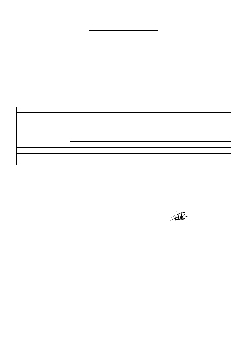
SPECIFICATIONS
Model BDF444 BDF454
Capacities
No load speed (min-1)
Overall length 231 mm
Net weight 2.0 kg 2.1 kg
• Due to our continuing programme of research and development, the specifications herein are subject to change without notice.
• Note: Specifications may differ from country to country.
Rated voltage D.C. 14.4 V D.C. 18 V
Intended use
The tool is intended for drilling and screw driving in wood,
metal and plastic.
For European countries only
Noise
The typical A-weighted noise level determined according
to EN60745-2-1:
Sound pressure level (L
Uncertainty (K) : 3 dB(A)
) : 73 dB(A)
pA
The noise level under working may exceed 85 dB (A).
Wear ear protection.
Vibration
The vibration total value (tri-axial vector sum)
determined according to EN60745-2-1:
Work mode: Drilling into metal
Vibration emission (a
) : 2.5 m/s2 or less
h,D
EC-DECLARATION OF CONFORMITY
Model; BDF444,BDF454
We declare under our sole responsibility that this
product is in compliance with the following standards of
standardized documents;
EN60745, EN55014 in accordance with Council
Directives, 2004/108/EC, 98/37/EC.
CE2007
Steel 13 mm 13 mm
Wood 50 mm 65 mm
Wood screw 6 mm x 75 mm 10 mm x 89 mm
Machine screw 6 mm
High (2) 0 - 1,700
Low (1) 0 - 400
ENE034-1
Director
ENG101-1
000230
Tomoyasu Kato
Responsible Manufacturer:
Makita Corporation
3-11-8, Sumiyoshi-cho, Anjo, Aichi, JAPAN
Authorized Representative in Europe:
Makita International Europe Ltd.
Michigan Drive, Tongwell, Milton Keynes, Bucks MK15
8JD, ENGLAND
ENG202-1
SPECIFIC SAFETY RULES
DO NOT let comfort or familiarity with product
(gained from repeated use) replace strict adherence
ENH102-7
to drill safety rules. If you use this power tool
unsafely or incorrectly, you can suffer serious
personal injury.
1. Use auxiliary handles supplied with the tool.
Loss of control can cause personal injury.
2. Hold power tools by insulated gripping
surfaces when performing an operation where
the cutting tool may contact hidden wiring or
its own cord. Contact with a "live" wire will make
exposed metal parts of the tool "live" and shock
the operator.
4
GEB001-2

3. Always be sure you have a firm footing.
Be sure no one is below when using the tool in
high locations.
4. Hold the tool firmly.
5. Keep hands away from rotating parts.
6. Do not leave the tool running. Operate the tool
only when hand-held.
7. Do not touch the drill bit or the workpiece
immediately after operation; they may be
extremely hot and could burn your skin.
8. Some material contains chemicals which may
be toxic. Take caution to prevent dust
inhalation and skin contact. Follow material
supplier safety data.
SAVE THESE INSTRUCTIONS.
WARNING:
MISUSE or failure to follow the safety rules stated in
this instruction manual may cause serious personal
injury.
ENC007-2
IMPORTANT SAFETY
INSTRUCTIONS
FOR BATTERY CARTRIDGE
1. Before using battery cartridge, read all
instructions and cautionary markings on (1)
battery charger, (2) battery, and (3) product
using battery.
2. Do not disassemble battery cartridge.
3. If operating time has become excessively
shorter, stop operating immediately. It may
result in a risk of overheating, possible burns
and even an explosion.
4. If electrolyte gets into your eyes, rinse them
out with clear water and seek medical
attention right away. It may result in loss of
your eyesight.
5. Do not short the battery cartridge:
(1) Do not touch the terminals with any
conductive material.
(2) Avoid storing battery cartridge in a
container with other metal objects such as
nails, coins, etc.
(3) Do not expose battery cartridge to water
or rain.
A battery short can cause a large current
flow, overheating, possible burns and
6. Do not store the tool and battery cartridge in
even a breakdown.
locations where the temperature may reach or
exceed 50 ゚ C (122 ゚ F).
7. Do not incinerate the battery cartridge even if
it is severely damaged or is completely worn
out. The battery cartridge can explode in a fire.
8. Be careful not to drop or strike battery.
SAVE THESE INSTRUCTIONS.
Tips for maintaining maximum battery life
1. Charge the battery cartridge before completely
discharged.
Always stop tool operation and charge the
battery cartridge when you notice less tool
power.
2. Never recharge a fully charged battery
cartridge.
Overcharging shortens the battery service life.
3. Charge the battery cartridge with room
temperature at 10 ゚ C - 40 ゚ C (50 ゚ F - 104 ゚ F).
Let a hot battery cartridge cool down before
charging it.
FUNCTIONAL DESCRIPTION
CAUTION:
• Always be sure that the tool is switched off and the
battery cartridge is removed before adjusting or
checking function on the tool.
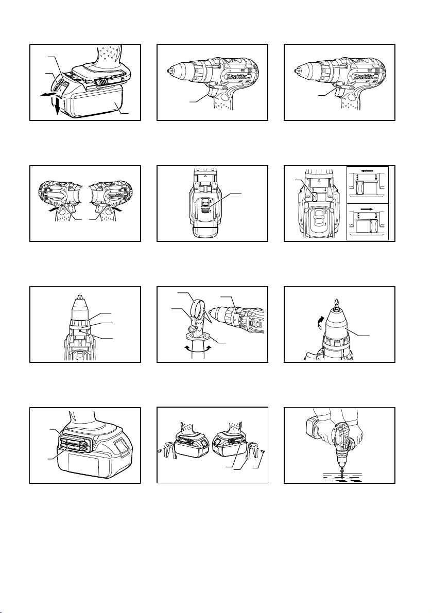
Installing or removing battery cartridge
Fig.1
• Always switch off the tool before insertion or
removal of the battery cartridge.
• To remove the battery cartridge, withdraw it from
the tool while sliding the button on the front of the
cartridge.
• To insert the battery cartridge, align the tongue on
the battery cartridge with the groove in the housing
and slip it into place. Always insert it all the way
until it locks in place with a little click. If you can
see the red part on the upper side of the button, it
is not locked completely. Insert it fully until the red
part cannot be seen. If not, it may accidentally fall
out of the tool, causing injury to you or someone
around you.
• Do not use force when inserting the battery
cartridge. If the cartridge does not slide in easily, it
is not being inserted correctly.
Switch action
Fig.2
CAUTION:
• Before inserting the battery cartridge into the tool,
always check to see that the switch trigger
actuates properly and returns to the "OFF" position
when released.
To start the tool, simply pull the switch trigger. Tool
speed is increased by increasing pressure on the switch
trigger. Release the switch trigger to stop.
5

Lighting up the front lamp
Fig.3
CAUTION:
• Do not look in the light or see the source of light
directly.
Pull the switch trigger to light up the lamp. The lamp
keeps on lighting while the switch trigger is being pulled.
The lamp goes out 10 -15 seconds after releasing the
trigger.
NOTE:
• Use a dry cloth to wipe the dirt off the lens of lamp.
Be careful not to scratch the lens of lamp, or it may
lower the illumination.
Reversing switch action
Fig.4
This tool has a reversing switch to change the direction
of rotation. Depress the reversing switch lever from the A
side for clockwise rotation or from the B side for
counterclockwise rotation.
When the reversing switch lever is in the neutral position,
the switch trigger cannot be pulled.
CAUTION:
• Always check the direction of rotation before
operation.
• Use the reversing switch only after the tool comes
to a complete stop. Changing the direction of
rotation before the tool stops may damage the tool.
• When not operating the tool, always set the
reversing switch lever to the neutral position.
Speed change
Fig.5
To change the speed, first switch off the tool and then
slide the speed change lever to the "2" side for high
speed or, "1" side for low speed. Be sure that the speed
change lever is set to the correct position before
operation. Use the right speed for your job.
CAUTION:
• Always set the speed change lever fully to the
correct position. If you operate the tool with the
speed change lever positioned halfway between
the "1" side and , "2" side, the tool may be
damaged.
• Do not use the speed change lever while the tool is
running. The tool may be damaged.
Selecting action mode
Fig.6
This tool has an action mode change lever. For drilling,
slide the action mode change lever to the left (
For screwing, slide the action mode change lever to the
right (
symbol).
symbol).
NOTE:
• When changing the position from " " to " ", it
may be a little difficult to slide the mode change
lever. At this time, switch on and run the tool for a
second at the "
" position, then stop the tool and
slide to your desired position.
CAUTION:
• Always slide the action mode change lever all the
way to your desired mode position. If you operate
the tool with the lever positioned halfway between
the mode symbols, the tool may be damaged.
• Do not use the action mode change lever while the
tool is running. The tool may be damaged.
Adjusting the fastening torque
Fig.7
The fastening torque can be adjusted in 16 steps by
turning the adjusting ring so that its graduations are
aligned with the pointer on the tool body.
First, slide the action mode change lever to the position
of
symbol.
The fastening torque is minimum when the number 1 is
aligned with the pointer, and maximum when the
marking is aligned with the pointer. The clutch will slip at
various torque levels when set at the number 1 to 16.
Before actual operation, drive a trial screw into your
material or a piece of duplicate material to determine
which torque level is required for a particular application.
NOTE:
• The adjusting ring does not lock when the pointer
is positioned only halfway between the
graduations.
ASSEMBLY
CAUTION:
• Always be sure that the tool is switched off and the
battery cartridge is removed before carrying out
any work on the tool.
Installing side grip (auxiliary handle)
Fig.8
Always use the side grip to ensure operating safety.
Insert the side grip so that the protrusions on the grip
base and steel band fit in between the grooves on the
tool barrel. Then tighten the grip by turning clockwise.
Installing or removing driver bit or drill bit
Fig.9
Turn the sleeve counterclockwise to open the chuck
jaws. Place the bit in the chuck as far as it will go. Turn
the sleeve clockwise to tighten the chuck. To remove the
bit, turn the sleeve counterclockwise.
6
Installing bit holder
Fig.10
Fit the bit holder into the protrusion at the tool foot on
eithher right or left side and secure it with a screw.
When not using the driver bit, keep it in the bit holders.
Bits 45 mm long can be kept there.
Hook
Fig.11
The hook is convenient for temporarily hanging the tool.
This can be installed on either side of the tool.
To install the hook, insert it into a groove in the tool
housing on either side and then secure it with a screw.
To remove, loosen the screw and then take it out.
OPERATION
Screwdriving operation
Fig.12
First, slide the action mode change lever so that it points
to the
marking. Adjust the adjusting ring to the proper
torque level for your work. Then proceed as follows.
Place the point of the driver bit in the screw head and
apply pressure to the tool. Start the tool slowly and then
increase the speed gradually. Release the switch trigger
as soon as the clutch cuts in.
NOTE:
• Make sure that the driver bit is inserted straight in
the screw head, or the screw and/or bit may be
damaged.
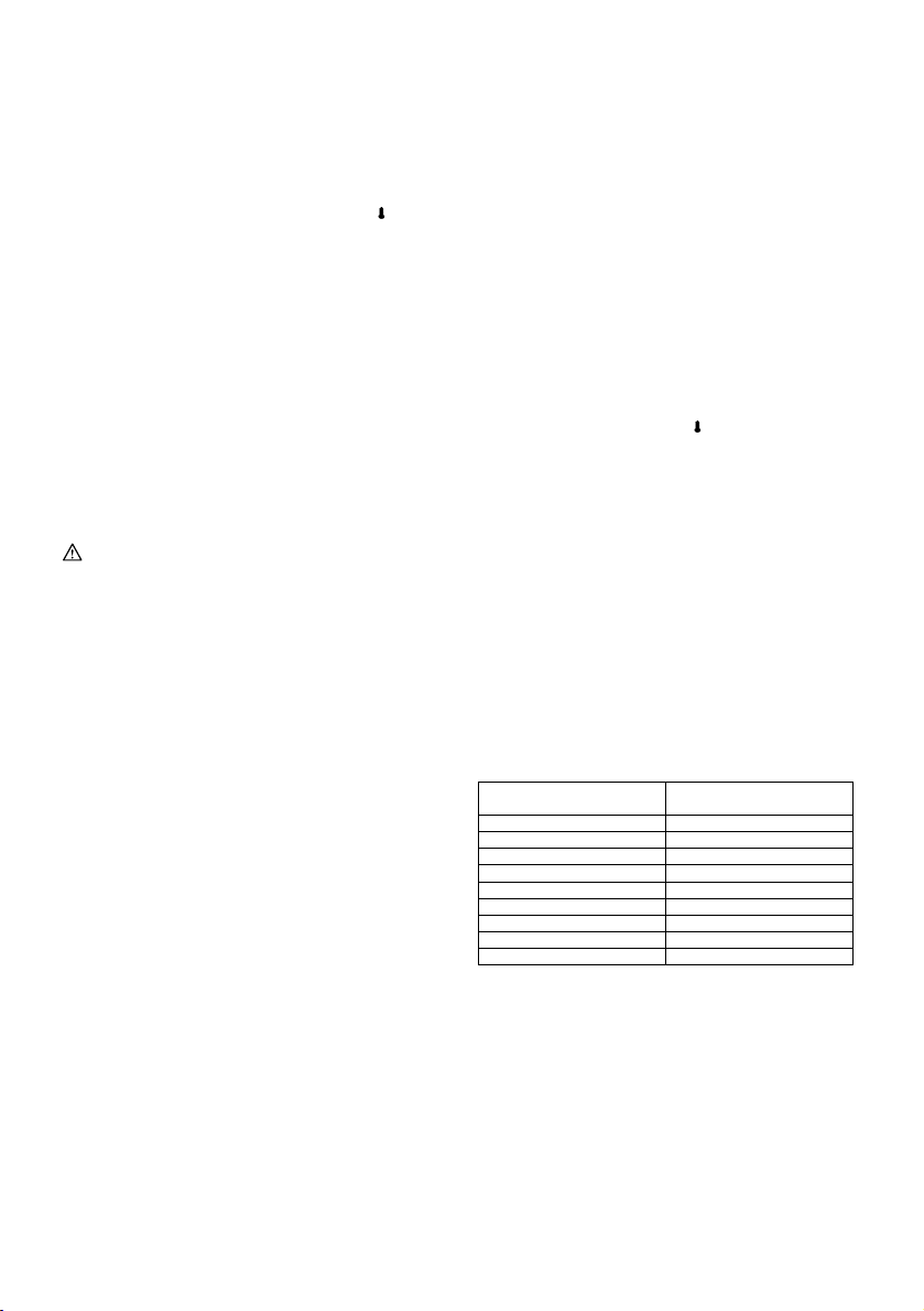
• When driving wood screws, predrill pilot holes to
make driving easier and to prevent splitting of the
workpiece. See the chart.
Nominal diameter of wood screw
006421
(mm)
3.1 2.0 - 2.2
3.5 2.2 - 2.5
3.8 2.5 - 2.8
4.5 2.9 - 3.2
4.8 3.1 - 3.4
5.1 3.3 - 3.6
5.5 3.7 - 3.9
5.8 4.0 - 4.2
6.1 4.2 - 4.4
NOTE:
• If the tool is operated continuously until the battery
cartridge has discharged, allow the tool to rest for
15 minutes before proceeding with a fresh battery.
Drilling operation
Drilling in wood
When drilling in wood, the best results are obtained with
wood drills equipped with a guide screw. The guide
screw makes drilling easier by pulling the bit into the
workpiece.
Recommended size of pilot hole
(mm)
Drilling in metal
To prevent the bit from slipping when starting a hole,
make an indentation with a center-punch and hammer at
the point to be drilled. Place the point of the bit in the
indentation and start drilling.
Use a cutting lubricant when drilling metals. The
exceptions are iron and brass which should be drilled
dry.
First, slide the action mode change lever so that it points
to the
marking. The adjusting ring can be aligned in
any torque levels for this operation. Then proceed as
follows.
CAUTION:
• Pressing excessively on the tool will not speed up
the drilling. In fact, this excessive pressure will only
serve to damage the tip of your bit, decrease the
tool performance and shorten the service life of the
tool.
• There is a tremendous force exerted on the tool/bit
at the time of hole break through. Hold the tool
firmly and exert care when the bit begins to break
through the workpiece.
• A stuck bit can be removed simply by setting the
reversing switch to reverse rotation in order to back
out. However, the tool may back out abruptly if you
do not hold it firmly.
• Always secure small workpieces in a vise or similar
hold-down device.
• If the tool is operated continuously until the battery
cartridge has discharged, allow the tool to rest for
15 minutes before proceeding with a fresh battery.
MAINTENANCE
CAUTION:
• Always be sure that the tool is switched off and the
battery cartridge is removed before attempting to
perform inspection or maintenance.
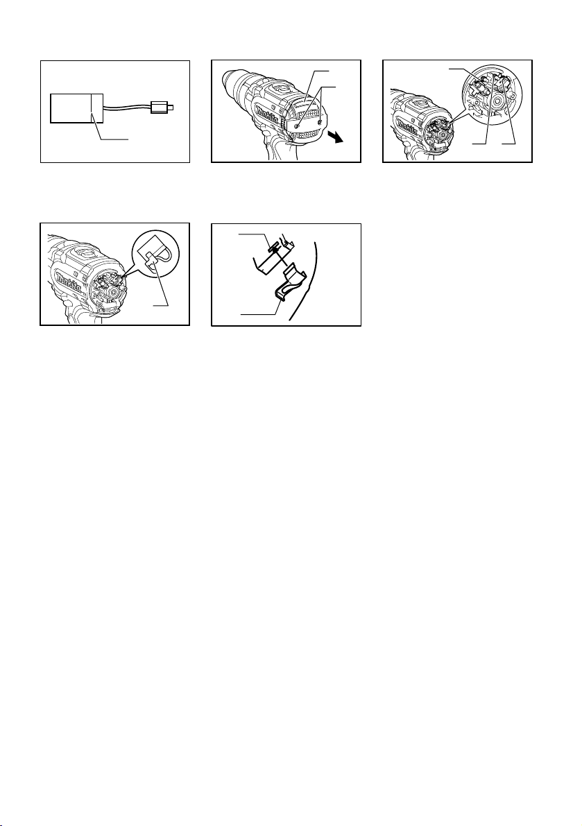
Replacing carbon brushes
Fig.13
Replace when they wear down to the limit mark. Keep
the carbon brushes clean and free to slip in the holders.
Both carbon brushes should be replaced at the same
time. Use only identical carbon brushes.
Use a screwdriver to remove two screws then remove
the rear cover.
Fig.14
Raise the arm part of the spring and then place it in the
recessed part of the housing with a slotted bit
screwdriver of slender shaft or the like.
Fig.15
Use pliers to remove the carbon brush caps of the
carbon brushes. Take out the worn carbon brushes,
insert the new ones and replace the carbon brush caps
in reverse.
7

Fig.16
Make sure that the carbon brush caps have fit into the
holes in brush holders securely.
Fig.17
Reinstall the rear cover and tighten two screws securely.
To maintain product SAFETY and RELIABILITY, repairs,
any other maintenance or adjustment should be
performed by Makita Authorized Service Centers,
always using Makita replacement parts.
ACCESSORIES
CAUTION:
• These accessories or attachments are
recommended for use with your Makita tool
specified in this manual. The use of any other
accessories or attachments might present a risk of
injury to persons. Only use accessory or
attachment for its stated purpose.
If you need any assistance for more details regarding
these accessories, ask your local Makita Service Center.
• Drill bits
• Screw bits
• Hook
• Grip assembly
• Various type of Makita genuine batteries and
chargers
• Rubber pad assembly
• Wool bonnet
• Foam polishing pad
8
УКРАЇНСЬКА
1-1. Червона частина
1-2. Кнопка
1-3. Касета з акумулятором
2-1. Кнопка вимикача
3-1. Ліхтар
4-1. Важіль перемикача реверсу
5-1. Важіль зміни швидкості
6-1. Важіль зміни режиму роботи
7-1. Кільце регулювання
7-2. Градуювання
7-3. Стрілка
Пояснення до загального виду
8-1. Сталева смуга
8-2. Основа ручки
8-3. Бокова рукоятка
8-4. Виступ
8-5. Паз
9-1. Муфта
10-1. Обойма для свердел
10-2. Свердло
11- 1. Паз
11- 2. Скоба
11- 3. Гвинт
Обмежувальна від
13-1.
мітка
14-1. Задня кришка
14-2. Гвинти
15-1. Плече
15-2. Пружина
15-3. Заглиблена частина
16-1. Ковпачок графітової щітки
17-1. Отвір
17-2. Ковпачок графітової щітки
ТЕХНІЧНІ ХАРАКТЕРИСТИКИ
Модель BDF444 BDF454
Діаметр свердління
Швидкість холостого ходу
• Через те, що ми не припиняємо програми досліджень і розвитку, наведені тут технічні характеристики можуть бути змінені
без попередження.
• Примітка. У різних країнах технічні характеристики можуть бути різними.
-1
)
(хв
Загальна довжина 231 мм
Чиста вага 2,0 кг 2,1 кг
Номінальна напруга 14,4 В пост. Ток а 18 В пост. Ток а
Призначення
Інструмент призначено для свердління та
встановлення гвинтів у деревину, метал та
пластмасу.
Для Європейських країн тільки
Шум
Рівень шуму за шкалою А у типовому виконанні
визначений відповідно до EN60745-2-1:
Рівень звукового тиску (L
Погрішність (К): 3 дБ(A)
Рівень шуму під час роботи може перевищувати 85
дБ (А).
Користуйтеся засобами захисту слуху.
Вібрація
Загальна величина вібрації (сума трьох векторів)
визначається згідно EN60745-2-1:
Режим роботи: Свердління металу
Вібрація (a
) : 2.5 м/с2 або менше
год,D
ДЕКЛАРАЦІЯ ВІДПОВІДНОСТІ ЄС
Модель; BDF444,BDF454
Ми заявляємо під нашу виключну відповідальність,
що цей виріб відповідає вимогам наведених нижче
Сталь 13 мм 13 мм
Деревина 50 мм 65 мм
Шуруп 6 мм x 75 мм 10 мм x 89 мм
Гвинт для металу 6 мм
Високий (2) 0 - 1700
Низький (1) 0 - 400
ENE034-1
стандартів нормативної документації;
EN60745, EN55014 згідно з Керівними Інструкціями
Ради, 2004/108/EC, 98/37/EC.
CE2007
ENG101-1
000230
Том оя зу Като
Директор
) : 73 дБ(A)
pA
Виконавчий виробник:
Makita Corporation
3-11-8, Sumiyoshi-cho, Anjo, Aichi, ЯПОНІЯ
Повноважний представник у Європі:
Makita International Europe Ltd.
ENG202-1
Michigan Drive, Tongwell, Milton Keynes, Bucks MK15
8JD АНГЛІЯ
Особливі правила техніки
ENH102-7
безпеки
НЕ ДОЗВОЛЯЙТЕ недбалого поводження з цим
виробом (яке з'являється після регулярного
використання) замість суворого дотримання
правил безпеки при роботі з дрилем. При
використанні цього електроінструменту із
GEB001-2
9

порушенням правил техніки безпеки або на за
призначенням, Ви можете отримати серйозну
травму.
1. Користуйтесь додатковими рукоятками, що
постачаються з інструментом. Втрата
контролю призводить до травматизму.
2. При виконуванні робіт, при яких ріжучий
інструмент може контактувати зі схованою
проводкою або власним шнуром, необхідно
тримати електро інструмент за ізольовані
поверхні рукояток. Контакт з про
призведе до її попадання на відкриті металеві
деталі інструмента і може уразити користувача
електричним струмом .
3. Завжди майте тверду опору.
При виконанні висотних робіт
переконайтеся, що під Вами нікого немає.
4. Міцно тримайте інструмент.
5. Не торкайтесь руками частин, що
обертаються.
6. Не залишайте інструмент працюючим.
Працюйте з інструментом ті
тримаєте його в руках.
7. Не торкайтесь свердла або заготовки
одразу після свердління; вони можуть бути
дуже гарячими і спричинити опіки шкіри.
8. Деякі матеріали мають у своєму складі
токсичні хімічні речовини. Будьте уважні,
щоб запобігти вдихання пилу та контактів зі
шкірою. Дотримуйтеся правил техніки
безпеки виробника матеріалу .
одом фази
в
льки то
ді, коли
ЗБЕРІГАЙТЕ ЦІ ВКАЗІВКИ
УВАГА:
НЕДОТРИМАННЯ правил техніки безпеки,
наведених у цій інструкції з експлуатації, може
призвести до серйозного травмування.
ENC007-2
ВАЖЛИВІ ІНСТРУКЦІЇ БЕЗПЕКИ
ДЛЯ КАСЕТИ АКУМУЛЯТОРА
1. Перед тим як користуватися касетою
акумулятора, слід прочитати усі інструкції
та попереджуючі відмітки щодо (1)
зарядний пристрій акумулятора, (2)
акумулятор та (3) вироби, що працюють від
акумулятора.
2. Не слід розбирати касету ак умулятора.
3. Якщо період роботи дуже покоротшав, слід
негайно припинити користування. Це може
призвести до ризику перегріву, опіку та
навіть вибуху.
4. Якщо ел
промити їх чистою водою та негайно
звернутися за медичного закладу. Це може
ектроліт по
трапив до очей, слід
призвести до втрати зору.
5. Не замкніть касету акумулятора.
(1) Не слід торкатися клем будь яким
струмопровідним матеріалом.
(2) Не слід зберігати касету акумулятора в
ємності з іншими металевими
предметами, такими як цвяхи, монети і
т.д.
(3) Не за
6. Не слід зберігати інструмент та касету з
акумулятором в містах, де температура
може сягнути та перевищити 50гр.゚ C (122 ゚
F).
7. Не слід спалювати касе
навіть, якщо вона була неодноразово
пошкоджена або повністю спрацьована.
Касета з акумулятором може вибухнути в
огні.
8. Не слід кидати або ударяти акумулятор.
ишайте касету акумулятора під
л
дощем, запобігайте контакту з водою.
Коротке замикання може призвести до
великого струму, перегріву, можливих
опіків та навіть виходу з ладу.
умулятором
ту з ак
ЗБЕРІГАЙТЕ ЦІ ВКАЗІВКИ
Поради по забезпеченню максимального
строку експлуатації акумулятора
1. Касету з акумулятором слід заряджати до
того, як він розрядиться повністю.
Завжди слід зупинити роботу інструменту
та зарядити акумулятор, якщо ви помітили
зменшення потужності інструменту.
2. Ніколи не слід заряджати повторно
повністю заряджену касету з акумулятором.
Перезарядження скорочує строк
експлуатації акумулятора.
3. Касету з акумулятором слід заряджати при
кімнатній температурі 10 ゚ C - 40 ゚ C (50 ゚ F -
104 ゚ F).
Перед ти
акумулятором слід залишити її доки вона не
остигне.
м як заряджати касету з
ІНСТРУКЦІЯ З ВИКОРИСТАННЯ
ОБЕРЕЖНО:
• Завжди перевіряйте, щоб прилад був
вимкнений, а касета з акумулятором була знята,
перед регулюванням або перевіркою
функціонування інструмента.
Встановлення та зняття касети з
акумулятором.
Fig.1
• Перед тим, як встановлювати або знімати
касету з акумулятором, інструмент слід завжди
вимикати.
10

• Для того, щоб зняти касету з акумулятором, її
слід витягти з інструмента, натиснувши кнопку
спереду касети.
• Для того, щоб вставити касету з акумулятором,
слід сумістити шпонку касети з батареями із
пазом в корпусі та вставити касету. Касету слід
завжди вставляти до упору доки не почується
щиглик, і касету буде заблоковано в робочому
положенні. Якщо на верхній частині кнопки
видна червона частина, це означає, що вона
заблокована неповністю. Вставте ка
сету
повністю, доки червону частину не буде видно.
Якщо цього не зробити, то касета може
випадково випасти з інструмента та поранити
вас або людей, що знаходяться поряд.
• Не застосовуйте силу, вставляючи касету з
акумулятором. Якщо касета не вставляється
легко, то це означає, що ви її невірно
вставляєте.
Дія вимикача.
Fig.2
ОБЕРЕЖНО:
• Перед тим, як вставляти касету з акумулятором
в інструмент, слід перевірити належну роботу
курка вмикача, тобто щоб він повертався у
положення "ВИМК.", коли його відпускають.
Для того, щоб запустити інструмент, слід просто
натиснути на курок вмикача. Швидкість обертання
інструмента збільшується шляхом збільшення тиску
на курок вмикача. Для зупинення роботи курок слід
відп
устити.
Увімкнення переднього підсвічування
Fig.3
ОБЕРЕЖНО:
• Не дивіться на світло або безпосередньо на
джерело світла.
Натисніть на курок вмикача, щоб увімкнути переднє
підсвічування. Підсвічування горітиме. доки курок
вмикача буде натиснутий. Ліхтар гасне через 10-15
секунд після того, як курок вмикача був відпущений.
ПРИМІТКА:
• Для видалення бруду з лінзи підсвітки
користуйтесь сухою тканиною. Будьте обережні,
щоб не подряпати лінзу підсвітки, тому що
можна погіршити освітлювання.
Дія вимикача-реверсера.
Fig.4
Інструмент обладнаний перемикачем зворотного
ходу для зміни напрямку обертання. Для обертання
по годинниковій стрілці важіль-перемикач слід
пересунути в положення "А", проти годинникової
стрілки - в положення "В".
Коли важіль-перемикач поставлений в нейтральне
положення, курок е може бути натиснутий.
ОБЕРЕЖНО:
• Перед початком роботи слід завжди перевіряти
напрямок обертання.
• Перемикач зворотного ходу можна
використовувати тільки після повної зупинки
інструмента. Зміна напрямку обертання до
повної зупинки інструмента може його
пошкодити.
• Коли інструмент не використовується,
важіль-перемикач повинен знаходитись в
нейтральному положенні.
Зміна швидкості
Fig.5
Для зміни швидкості слід спочатку вимкнути
інструмент, а потім пересунути важіль зміни
швидкості в положення "2" для високої швидкості або
в положення "1" для низької. Перед тим, як починати
роботу, перевірте, щоб важіль зміни швидкості
знаходився у вірному положенні. Використовуйте
швидкість, що відповідає типу робіт.
ОБЕРЕЖНО:
• Важіль зміни швидкості слід завжди повністю
пересувати у належне положення. Якщо
інструмент експлуатується, коли важіль зміни
швидкості пересунутий наполовину між
положенням "1" та "2", інструмент може бути
пошкоджений.
• Неможна користуватись важелем зміни
швидкості, коли інструмент працює. Інструмент
може пошкодитись.
Вибір режиму роботи
Fig.6
Інструмент обладнаний важелем вибору режиму
роботи. Для свердління слід пересунути важіль зміни
режиму роботи вліво (символ
гвинтів слід пересунути важіль зміни режиму роботи
вправо (символ
).
ПРИМІТКА:
• Під час зміни положення з " " на " " важіль
можу бути дещо важко пересувати. В такому
разі інструмент слід увімкнути та дати йому
попрацювати протягом секунди в положенні "
а потім зупинити його та пересунути важіль у
необхідне положення.
ОБЕРЕЖНО:
• Слід завжди повністю пересувати важіль зміни
режиму роботи у необхідне положення. Якщо
інструмент експлуатувати із важелем
пересунутим наполовину між символами
режиму, інструмент може пошкодитись.
• Неможна користуватись важелем зміни режиму
роботи, коли інструмент працює. Інструмент
може пошкодитись.
11
). Для закручування
",
Регулювання моменту затягування
Fig.7
Момент затягування можна регулювати на 16
положень шляхом повертання кільця регулювання
таким чином, щоб його шкала суміщалась із стрілкою
на корпусі інструмента.
Спочатку слід пересунути важіль зміни режиму
роботи в положення, позначене символом
.
Момент затягування є мінімальним, коли покажчик
суміщений з номером "1", а максимальним - коли з
покажчиком суміщена мітка. Зчеплення
прослизатиме на моментах затягування різних рівнів
від номера 1 до 16. Перед тим, як власне починати
роботу, слід вкрутити пробний гвинт в матеріал або
деталь для того, щоб визначити рівень моменту
затягування, необхідного для даних робіт.
ПРИМІТКА:
• Кільце регулювання не замикається, коли
покажчик розташований між мітками
градуювання.
КОМПЛЕКТУВАННЯ
ОБЕРЕЖНО:
• Завжди перевіряйте, щоб прилад був
вимкнений, а касета з акумулятором була знята,
перед тим, як проводити будь-які роботи на
інструменті.
Установка бокової рукоятки (додаткова
рукоятка)
Fig.8
Для забезпечення безпечної роботи слід завжди
триматись за бокову ручку.
Встановіть бокову ручку таким чином, щоб виступи в
основі та на місці встановлення сталевої стяжки
ручки увійшли в пази на барабані інструмента. Після
цього ручку слід затягнути, повертаючи її по
годинниковій стрілці.
Встановлення та зняття викрутки або
свердла
Fig.9
Поверніть муфту проти годинниковій стрілки для того,
щоб відкрити кулачки патрона. Вставте свердло або
викрутку до упора. Поверніть муфту по годинниковій
стрілці, щоб затягнути кулачки патрона. Для того,
щоб зняти свердло, поверніть муфту проти
годинникової стрілки.
Встановлення обойми для свердел
Fig.10
Вставте одну обойму для свердел у виступ в нижній
частині інструмента з лівої або правої сторони та
закріпіть його за допомогою гвинта.
Коли викрутка не використовується, її слід зберігати в
обоймі для свердел. Там можна зберігати свердла
довжиною 45 мм.
Скоба
Fig.11
Гак є зручним для тимчасового підвішування
інструмента. Його можна встановлювати на будь-якій
стороні інструмента.
Для того, щоб встановити гак, його слід вставити в
паз на корпусі інструмента з будь-якої сторони та
закріпити його за допомогою гвинта. Для того, щоб
зняти гак, слід послабити гвинт та витягти його.
ЗАСТОСУВАННЯ
Операції з вгвинчування
Fig.12
Спочатку пересуньте важіль зміни режиму роботи так,
щоб він вказував на мітку
регулювання на величину обертального моменту,
необхідну для роботи. Потім виконайте наступні
кроки.
Вставте наконечник викрутки в голівку гвинта та
натисніть на інструмент. Повільно запустіть
інструмент, а потім поступово збільшуйте швидкість.
Курок слід відпускати одразу після того, як було
задіяне зчеплення.
ПРИМІТКА:
• Перевірте, щоб викрутка була рівно вставлена в
голівку гвинта, інакше гвинт та/або викрутка
можуть пошкодитись.
• Під час вгвинчування гвинтів для деревини слід
просвердлити напрямні отвори для полегшення
вгвинчування та запобігання розтріскуванню
деталі. Див. таблицю.
Номінальний діаметр гвинта для деревини
006421
(мм)
3,1 2,0 - 2,2
3,5 2,2 - 2,5
3,8 2,5 - 2,8
4,5 2,9 - 3,2
4,8 3,1 - 3,4
5,1 3,3 - 3,6
5,5 3,7 - 3,9
5,8 4,0 - 4,2
6,1 4,2 - 4,4
ПРИМІТКА:
• Якщо інструмент експлуатується постійно, доки
не розрядиться касета з акумулятором, то
перед тим, як встановлювати новий акумулятор,
інструментові треба дати відпочити протягом 15
хвилин.
Відрегулюйте гвинт
Рекомендований розмір напрямного отвору
(мм)
12

Свердління
Свердління деревини
При свердлінні по деревині найкращі результати
досягаються, коли свердла для деревини оснащені
напрямним гвинтом. Напрямний гвинт полегшує
свердління тим, що він втягує свердло в заготовку.
Свердління металу
Щоб запобігти прослизанню свердла на початку
свердління, місце свердління необхідно накернити.
Помістіть кінець свердла в накернене місце і
починайте свердління.
При свердлінні ме
талів в
икористовується
змащувально-охолоджувальна рідина. Виключення
становлять чавун та мідь, які свердлять насуху.
Спочатку пересуньте важіль зміни режиму роботи так,
щоб він вказував на мітку
. Під час цієї операції
кільце регулювання можна виставити на будь-яке
значення моменту. Потім виконайте наступні кроки.
ОБЕРЕЖНО:
• Надмірний тиск на інструмент не пришвидшує
свердління. Насправді надмірний тиск може
лише пошкодити свердло, зменшити
продуктивність інструменту та вкоротити термін
його експлуатації.
• Під час пробивання отвору до
інструмента/наконечника прикладається
величезне зусилля. Слід тримати інструмент
міцно та бути обережним, коли наконечник
починає входити в деталь.
• Свердло, яке заклинило, можна легко видалити,
встановивши перемикач реверсу на зворотній
напрямок обертання, щоб отримати задній хід.
Однак, задній хід інструменту може бути надто
різким, якщо Ви не будете його міцно тримати.
• Невелику заготовку слід затискувати в лещата
або подібний пристрій.
• Якщо інструмент експлуатується постійно, доки
не розрядиться касета з акумулятором, то
перед тим, як встановлювати новий акумулятор,
інструментові треба дати відпочити протягом 15
хвилин.
ТЕХНІЧНЕ ОБСЛУГОВУВАННЯ
ОБЕРЕЖНО:
• Завжди перевіряйте, щоб прилад був
вимкнений, а касета з акумулятором була знята,
перед проведенням перевірки або
обслуговування.
Заміна вугільних щіток
Fig.13
У разі зносу до обмежуючої мітки, провести заміну.
Графітові щітки слід тримати чистими та
незаблокованими, щоб вони могли заходити в
держаки. Обидві графітові щітки слід заміняти разом.
Можна використовувати тільки такі ж щітки.
Витягніть два гвинта за допомогою викрутки, а потім
зніміть задню кришку.
Fig.14
Підніміть плече пружини, а потім вставте його в
поглиблення на корпусі за допомогою викрутки із
шліцованим наконечником та прямим черешком або
подібного інструмента.
Fig.15
Для того, щоб зняти ковпачки графітових щіток,
використовуйте плоскогубці. Витягніть зношені
графітові щітки, вставте нові та замініть ковпачки
графітової щітки у зворотному порядку.
Fig.16
Перевірте, щоб ковпачки графітової щітки надійно
увійшли в отвори держаків щіток.
Fig.17
Поставте на місце кришку та надійно затягніть
обидва гвинти.
Для того, щоб підтримувати БЕЗПЕКУ та
НАДІЙНІСТЬ, ремонт, технічне обслуговування або
регулювання мають виконувати уповноважені центри
обслуговування "Макіта", де використовуються лише
стандартні запчастини "Макіта".
ОСНАЩЕННЯ
ОБЕРЕЖНО:
• Це оснащення або приладдя рекомендовано
для використання з інструментами "Макіта", що
описані в інструкції з експлуатації.
Використання якогось іншого оснащення або
приладдя може спричинити травмування.
Оснащення або приладдя слід використовувати
лише за призначенням.
У разі необхідності, отримати допомогу в більш
детальному ознайомленні з оснащенням звертайтесь
до місцевого Сервісного центру "Макіта".
• Свердла
• Викрутки
• Скоба
• Рукояка у зборі
• Різні типи оригінальних акумуляторів та
зарядних пристроїв виробництва компанії
Makita
• Вузол гумової пластини
• Матер'яний кожух
• Полірувальник з пінопласту
13

POLSKI
1-1. Czerwony element
1-2. Przycisk
1-3. Akumulator
2-1. Spust przełącznika
3-1. Lampka
4-1. Dźwignia przełącznika obrotów
wstecznych
5-1. Dźwignia zmiany prędkości
6-1. Dźwignia zmiany trybu pracy
7-1. Pierścień regulacyjny
7-2. Skala
Objaśnienia do widoku ogólnego
7-3. Strzałka
8-1. Opaska stalowa
8-2. Podstawa uchwytu
8-3. Uchwyt boczny
8-4. Występ
8-5. Bruzda
9-1. Tuleja
10-1. Uchwyt na końcówki
10-2. Wiertło
11- 1. Br uz da
11- 2. Ha k
11-3. Śruba
13-1. Znak ograniczenia
14-1. Osłona tylna
14-2. Wkręty
15-1. Ramię
15-2. Sprężyna
15-3. Gniazdo
16-1. Nasadka szczotki węglowej
17-1. Otwór
17-2. Nasadka szczotki węglowej
SPECYFIAKCJE
Model BDF444 BDF454
Wydajność
Wkręt do elementów metalowych
Prędkość bez obciążenia
• W związku ze stale prowadzonym przez naszą firmę programem badawczo-rozwojowym, niniejsze specyfikacje mogą ulec zmianom
bez wcześniejszego powiadomienia.
• Uwaga: Specyfikacje mogą różnić się w zależności od kraju.
-1
)
(min
Długość całkowita 231 mm
Ciężar netto 2,0 kg 2,1 kg
Napięcie znamionowe Prąd stały 14,4 V Prąd stały 18 V
Przeznaczenie
Narzędzie przeznaczone jest do wiercenia w drewnie,
metalu i tworzywach sztucznych oraz do wkręcania
wkrętów we wspomniane materiały.
Tylko dla krajów europejskich
Poziom hałasu i drgań
Typowy równoważny poziom dźwięku A określony w
oparciu o EN60745-2-1:
Poziom ciśnienia akustycznego (L
Niepewność (K): 3 dB (A)
Poziom hałasu podczas pracy może przekraczać 85 dB
(A).
Nosić ochronniki słuchu
Drgania
Całkowita wartość poziomu drgań (suma wektorów w 3
osiach) określona zgodnie z normą EN60745-2-1:
Tryb pracy: Wiercenie w metalu
Emisja drgań (a
) : 2.5 m/s2 lub poniżej
h,D
DEKLARACJA ZGODNOŚCI Z NORMAMI WE
Model; BDF444,BDF454
Deklarujemy, na naszą wyłączną odpowiedzialność, że
niniejszy produkt jest zgodny z następującymi normami
Stal 13 mm 13 mm
Drewno 50 mm 65 mm
Wkręt do drewna 6 mm x 75 mm 10 mm x 89 mm
Wysoka (2) 0 - 1 700
Niska (1) 0 - 400
ENE034-1
dokumentów normalizacyjnych;
6 mm
EN60745, EN55014 w świetle Dyrektyw Rady o
sygnaturach 2004/108/EC, 98/37/EC.
CE2007
ENG101-1
000230
Tomoyasu Kato
Dyrektor
) : 73 dB (A)
pA
Odpowiedzialny producent:
Makita Corporation
3-11-8, Sumiyoshi-cho, Anjo, Aichi, JAPAN
Autoryzowany przedstawiciel na Europę:
Makita International Europe Ltd.
ENG202-1
Michigan Drive, Tongwell, Milton Keynes, Bucks MK15
8JD, ANGLIA
Szczególne zasady
ENH102-7
bezpieczeństwa
NIE DOPUŚCIĆ, aby dobre obeznanie i
przyzwyczajenie do wyrobu (zdobyte przez częste
użytkowanie) zastąpiło ścisłe przestrzeganie zasad
bezpieczeństwa. Poprzez użytkowanie niniejszego
elektronarzędzia w sposób niebezpieczny lub
GEB001-2
14

nieprawidłowy, można doznać poważnych obrażeń
ciała.
1. Stosować uchwyty pomocnicze przewidziane
dla elektronarzędzia. Brak kontroli może
spowodować obrażenia ciała.
2. Podczas wykonywania pracy narzędziem
tnącym, trzymać elektronarzędzie za
izolowane powierzchnie uchwytów, ponieważ
ostrze narzędzia może natrafić na przewód
ukryty w materiale lub zetknąć się z
przewodem zasilania. Kontakt z przewodem pod
napięciem spowoduje przepływ prądu do
metalowych zewnętrznych części
elektronarzędzia i porażenie operatora.
3. Zapewnić stałe podłoże.
Upewnić się, czy nikt nie znajduje się poniżej
miejsca pracy na wysokości.
4. Tr
5. Tr zymać ręce z dala od części obrotowych.
6. Nie pozostawiać załączonego elektronarzędzia.
7. Nie dotykać końcówki wiertła lub części
8. Niektóre materiały zawierają substancje
narzędzie w sposób niezawodny.
zym ać
Można uruchomić elektronarzędzie tylko
wtedy, gdy jest trzymane w rękach.
obrabianej bezpośrednio po operacji; mogą
one być bardzo gorące i przypalić skórę.
chemiczne, które mogą być toksyczne. Unikać
wdychania i kontaktu ze skórą. Przestrzegać
przepisów bezpieczeństwa podanych przez
dostawcę materiałów.
ZACHOWAĆ INSTRUKCJE
OSTRZEŻENIE:
NIEPRAWIDŁOWE STOSOWANIE lub
nieprzestrzeganie zasad bezpieczeństwa
określonych w niniejszej instrukcji obsługi może
spowodować poważne obrażenia ciała.
ENC007-2
WAŻNE ZASADY
4. W przypadku przedostania się elektrolitu do
5. Nie doprowadzać do zwarcia akumulatora:
6. Narzędzia i akumulatora nie wolno
7. Akumulatorów nie wolno palić, również tych
8. Chronić akumulator przed upadkiem i
ZACHOWAĆ INSTRUKCJE
Wskazówki dotyczące zachowania
maksymalnej trwałości akumulatora
1. Akumulator należy naładować zanim zostanie
2. Nie wolno ładować powtórnie w pełni
3. Akumulator ładować w temperaturze
BEZPIECZEŃSTWA
DOTYCZĄCE AKUMULATORA
1. Przed użyciem akumulatora zapoznać się z
wszystkimi zaleceniami i znakami
ostrzegawczymi na (1) ładowarce, (2)
akumulatorze i (3) wyrobie, w którym będzie
używany akumulator.
2. Akumulatora nie wolno rozbierać.
3. Jeżeli czas pracy uległ znacznemu skróceniu,
należy natychmiast przerwać pracę. Może
bowiem dojść do przegrzania, ewentualnych
poparzeń, a nawet eksplozji.
OPIS DZIAŁANIA
• Przed przystąpieniem do regulacji lub przeglądu
Wkładanie i wyjmowanie akumulatora
Rys.1
• Przed włożeniem lub wyjęciem akumulatora należy
oczu, przemyć je wodą i niezwłocznie uzyskać
pomoc lekarską. Może on bowiem
spowodować utratę wzroku.
(1) Nie dotykać styków przedmiotami
wykonanymi z materiałów
przewodzących.
(2) Unikać przechowywania akumulatora w
pojemniku z metalowymi przedmiotami,
typu gwoździe, monety itp.
(3) Chronić akumulator przed deszczem lub
wodą.
Zwarcie prowadzi do przepływu prądu
elektrycznego o du
przegrzania akumulatora, co w
konsekwencji może grozić poparzeniami a
nawet awarią urządzenia.
przechowywać w miejscach, w których
temperatura osiąga bądź przekracza 50 ゚ C
(122 ゚ F).
poważnie uszkodzonych lub całkowicie
zużytych. W ogniu mogą one bowiem
eksplodować.
uderzeniami.
do końca rozładowany.
Gdy zauważysz spadek mocy narzędzia,
przerwij pracę i naładuj akumulator.
naładowanego akumulatora.
Przeładowanie akumulatora skraca jego czas
eksploatacji.
mieszczącej się w przedziale 10゚C - 40 ゚ C (50゚
F - 104 ゚ F). Gdy akumulator jest gorący, przed
przystąpieniem do jego ładowania odczekać,
aż ostygnie.
UWAGA:
narzędzia upewnić się, czy jest ono wyłączone i
czy został wyjęty akumulator.
koniecznie wyłączyć narzędzie.
żym
natężen
iu i
15
 Loading...