

Makita BDF441, BDF441SFE, BDF441SFE3 Technical Information
T
ECHNICAL INFORMATION
Model No.
Description
BDF441
Cordless Driver Drill 13mm (1/2")
CONCEPT AND MAIN APPLICATIONS
Model BDF441 has been developed as an upgraded sister model of Model 6339D
with the design concept of "More Control and Maneuverability".
Features lightweight and compact design achieved by using 4-pole motor and
Lithium-ion battery as power unit.
Also features the same advantages as BDF440:
Rubberized soft grip contoured to perfectly fit operator hand and angled
to provide best tool balance
All metal gear construction
Job light with afterglow function
Single sleeve chuck
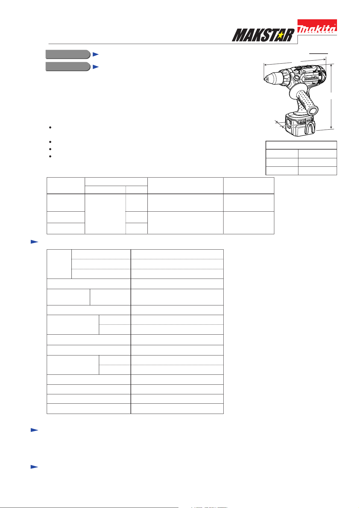
This new product will be available in the following variations.
PRODUCT
L
W
Dimensions: mm (")
Length (L)
Width (W)
Height (H)
238 (9-3/8)
78 (3-1/16)
P 1 / 7
H
255 (10)
Model No.
BDF441
BDF441SFE
BDF441SFE3 3
(Li-ion 3.0Ah)
Battery
type quantity
BL1430
2
2
DC18SC (Low voltage areas)
DC14SC (High voltage areas)
Specification
Voltage: V
Battery
Max output (W) 265
No load speed:
min-1=rpm
Capacity of drill chuck: mm (")
Capacity: mm (")
Torque setting
Max. clutch torque: N.m (ft.lbs)
Max. fastening
torque: N.m (ft.lbs)
Electric brake
Variable speed control
Reversing switch
Net weight*: kg (lbs)
Capacity: Ah
Cell
1st/ 2nd/ 3rd
0 - 300/ 0 - 600/ 0 - 1,700
1.5 - 13 (1/16 - 1/2)
Steel
Wood
16 stage + drill mode
1.0 - 5.9 (0.7 - 4.3)
Soft joint
Hard joint
Charger Offered to
DC18SC
14.4
3.0
Li-ion
13 (1/2)
50 (2)
32 (23.6)
70 (51.6)
Yes
Yes
Yes
2.0 (4.4)
USA, Canada
Mexico, Panama
All countries except
those listed above
*Includes battery BL1430
Standard equipment
Philips bit 2-45 ....... 2 pc
Bit holder................ 1 pc
Note: The standard equipment for the tool shown above may differ by country.
Belt clip................... 1 pc
Grip assembly.......... 1 pc
+ Screw M4x12 .............. 2 pc
Plastic carrying case ..... 1 pc
Optional accessories
Charger DC14SA
Charger DC14SC
Charger DC18SC
Charger DC24SA
Charger DC24SC
Li-ion battery BL1430
Assorted drill bits for wood
Assorted drill bits for metal
P 2 / 7
Repair
CAUTION: Remove the battery cartridge from the machine for safety before repair/maintenance !
[1] NECESSARY REPAIRING TOOLS
Description Use for
Hex wrench 10 Removing /mounting Drill chuck
Plastic hammer Removing Drill chuck
[2] LUBRICATION
It is not required to lubricate the gear section because the portion is replaced as a factory-lubricated gear unit.
[3] DISASSEMBLY/ASSEMBLY
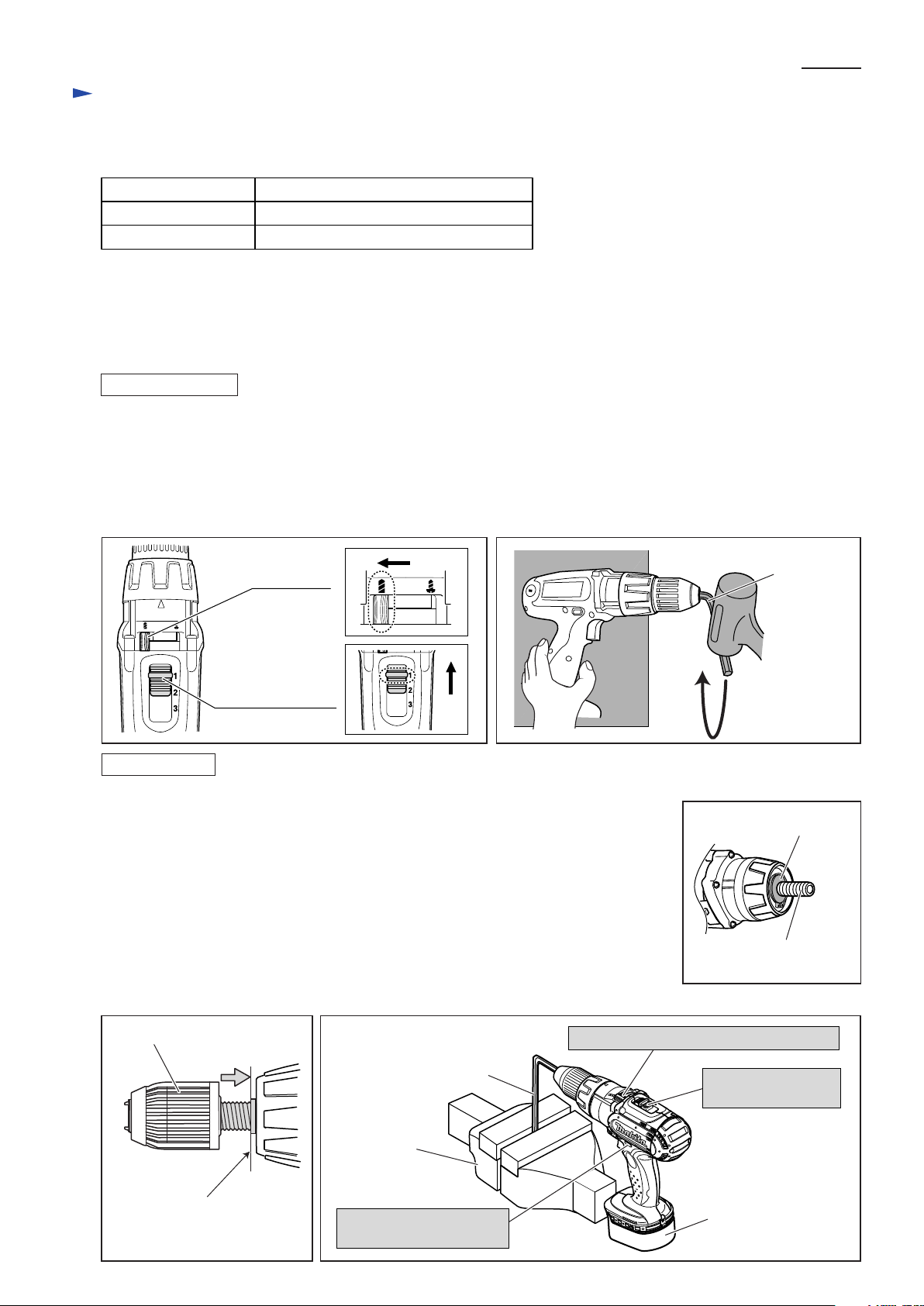
[3] -1. Drill Chuck
DISASSEMBLING
Note: It is required to remove Drill chuck when replacing Gear assembly, but you need not when replacing only Housing.
1) Open the jaws of Drill chuck fully, and remove the chuck screw (Flat head screw M6x22, left-handed and threadlocker
coated) by turning clockwise with impact driver in Forward rotation mode.
2) Insert a hex wrench into Drill chuck. Then set the Speed change lever in 1st speed, and Action mode change lever in
Drill mode as illustrated in Fig. 1. Holding the machine on work bench firmly, turn Drill chuck counter clockwise
by tapping the hex wrench. Now Drill chuck can be removed from Spindle. (Fig. 2)
Fig. 1
Fig. 2
Action mode
change lever
Speed change lever
ASSEMBLING
1) Make sure that Flat washer 13 is set in place before installing Drill chuck. (Fig. 3)
1) Turn Drill chuck clockwise until it sits on the end of the threaded portion of Spindle.
(Fig. 4)
2) See Fig. 5. Insert a hex wrench into drill chuck, and fix the other end of hex wrench
in vise. Install battery. Then set the Action mode change lever in Drill mode,
the Speed change lever in 1st speed, and F/R change lever in Forward rotation mode.
3) Slowly pull the switch trigger to rotate Spindle until the motor is locked.
Note: Pull the trigger so that Spindle reaches full speed in one second.
Important: Be sure to release the switch trigger just after Spindle is locked.
4) Secure Drill chuck with the chuck screw by turning counterclockwise with impact driver.
Note: If you reuse the removed chuck screw, apply threadlocker to threaded portion.
Fig. 4 Fig. 5
Hex wrench
Fig. 3
Flat washer 13
threaded portion
of Spindle
Drill chuck
End of the threaded
portion of Spindle
Hex wrench
Vise
F/R change lever:
in Forward rotation mode
Action mode change lever: in Drill mode
Speed change lever:
in 1st speed
Battery
Repair
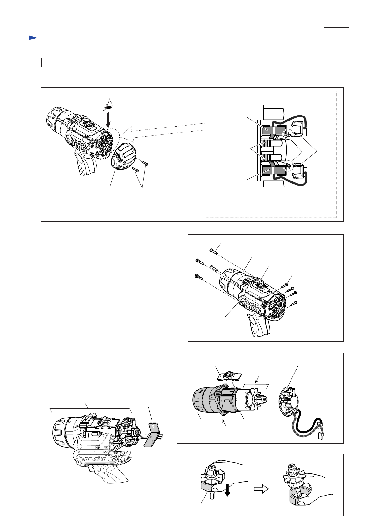
[3] -2. Gear Assembly and Motor Section
DISASSEMBLING
1) Remove Rear cover and take off Carbon brush from Brush holder complete. (Fig. 6)
Fig. 6
P 3 / 7
A
Rear cover
2) Unscrew four PT4x20 Tapping screws to disconnect
Gear assembly from Housing. Then by removing
eight PT3x16 Tapping screws, separate Housing R
from Housing L. (Fig. 7)
3) Pull off Heat sink from Yoke unit of the Motor section.
Then remove the assembly of the Gear section and
the Motor section from housing L. (Fig. 8)
3) Remove Brush holder complete from Armature,
then separate the Motor section from the Gear section.
(Fig. 9)
4) Put the Motor section on a work bench so that the
drive end of Armature touches the work bench.
Then separate yoke unit from armature by pulling it
down towards the work bench. (Fig. 10)
Tapping screw
bind PT 3x16
Fig. 7
Housing L
[Brush holder section (View from A)]
Carbon brush
Torsion spring
Carbon brush
1. Move the tail of Torsion spring onto the notch
of Brush holder.
2. Then pull off Receptacle from Brush holder.
Tapping screw bind PT4x20 (4 pcs)
Gear section (= Gear assembly)
Housing R
1 2
Tapping screw bind
PT3x16 (8 pcs)
Fig. 8 Fig. 9
Speed change lever assembly Brush holder complete
Assembly of the Gear section
and the Motor section
Heat sink
Fig. 10
Yoke unit
Motor section
Gear section
 Loading...