

Makita BDF343SHE, BDF343RHE User Manual [nl]
GB Cordless Driver Drill Instruction manual
F Perceuse-visseuse sans fil Manuel d’instructions
D Akku-Bohrschrauber Betriebsanleitung
I Trapano avvitatore a batteria Istruzioni per l’uso
NL Accuschroefboormachine Gebruiksaanwijzing
E Taladro sin cables Manual de instrucciones
P Berbequim sem fios Manual de instruções
DK Akku bore-skruemaskine Brugsanvisning
GR ∆ραπανοκατσάβιδο µπαταρίασ Οδηγίεσ χρήσησ
BDF343
BDF453
1
2
3
4
12
6
A
5
B
34
7
8
9
10
56
7
2

ENGLISH
Explanation of general view
1. Red part
2. Button
3. Battery cartridge
4. Switch trigger
5. Reversing switch lever
6. Speed change lever
7. Adjusting ring
8. Graduation
9. Pointer
10. Sleeve
SPECIFICATIONS
Model BDF343 BDF453
Steel 10 mm 13 mm
Capacities
No load speed (min
• Due to our continuing programme of research and development, the specifications herein are subject to change without
notice.
• Note: Specifications may differ from country to country.
Symbols
The following show the symbols used for the equipment.
Be sure that you understand their meaning before use.
............. Read instruction manual.
-1
)
Overall length 192 mm 214 mm
Net weight 1.3 kg (BL1415)/1.5 Kg (BL1430) 1.6 kg (BL1815)/1.8 Kg (BL1830)
Rated voltage D.C. 14.4 V D.C. 18 V
Wood 25 mm 36 mm
Wood screw 5.1 mm x 63 mm 6 mm x 75 mm
Machine screw 6 mm
High (2) 0 - 1,300
Low (1) 0 - 400
END004-2
SAVE THESE INSTRUCTIONS.
WARNING:
MISUSE or failure to follow the safety rules stated in
this instruction manual may cause serious personal
injury.
Intended use
The tool is intended for drilling and screw driving in wood,
metal and plastic.
ENE034-1
SPECIFIC SAFETY RULES GEB002-2
DO NOT let comfort or familiarity with product (gained
from repeated use) replace strict adherence to drill
safety rules. If you use this power tool unsafely or
incorrectly, you can suffer serious personal injury.
1. Hold power tools by insulated gripping surfaces
when performing an operation where the cutting
tool may contact hidden wiring or its own cord.
Contact with a “live” wire will make exposed metal
parts of the tool “live” and shock the operator.
2. Always be sure you have a firm footing. Be sure
no one is below when using the tool in high
locations.
3. Hold the tool firmly.
4. Keep hands away from rotating parts.
5. Do not leave the tool running. Operate the tool
only when hand-held.
6. Do not touch the drill bit or the workpiece
immediately after operation; they may be
extremely hot and could burn your skin.
7. Some material contains chemicals which may be
toxic. Take caution to prevent dust inhalation and
skin contact. Follow material supplier safety data.
IMPORTANT SAFETY
INSTRUCTIONS ENC007-2
FOR BATTERY CARTRIDGE
1. Before using battery cartridge, read all
instructions and cautionary markings on (1)
battery charger, (2) battery, and (3) product using
battery.
2. Do not disassemble battery cartridge.
3. If operating time has become excessively shorter,
stop operating immediately. It may result in a risk
of overheating, possible burns and even an
explosion.
4. If electrolyte gets into your eyes, rinse them out
with clear water and seek medical attention right
away. It may result in loss of your eyesight.
5. Do not short the battery cartridge:
(1) Do not touch the terminals with any
conductive material.
(2) Avoid storing battery cartridge in a container
with other metal objects such as nails, coins,
etc.
(3) Do not expose battery cartridge to water or
rain. A battery short can cause a large current
flow, overheating, possible burns and even a
breakdown.
3

6. Do not store the tool and battery cartridge in
locations where the temperature may reach or
exceed 50°C (122°F).
7. Do not incinerate the battery cartridge even if it is
severely damaged or is completely worn out. The
battery cartridge can explode in a fire.
8. Be careful not to drop or strike battery.
SAVE THESE INSTRUCTIONS.
Tips for maintaining maximum battery life
1. Charge the battery cartridge before completely
discharged. Always stop tool operation and
charge the battery cartridge when you notice less
tool power.
2. Never recharge a fully charged battery cartridge.
Overcharging shortens the battery service life.
3. Charge the battery cartridge with room
temperature at 10°C - 40°C (50°F - 104°F). Let a hot
battery cartridge cool down before charging it.
FUNCTIONAL DESCRIPTION
CAUTION:
• Always be sure that the tool is switched off and the
battery cartridge is removed before adjusting or
checking function on the tool.
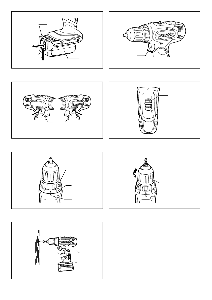
Installing or removing battery cartridge
(Fig. 1)
• Always switch off the tool before insertion or removal of
the battery cartridge.
• To remove the battery cartridge, withdraw it from the
tool while sliding the button on the front of the cartridge.
• To insert the battery cartridge, align the tongue on the
battery cartridge with the groove in the housing and slip
it into place. Always insert it all the way until it locks in
place with a little click. If you can see the red part on
the upper side of the button, it is not locked completely.
Insert it fully until the red part cannot be seen. If not, it
may accidentally fall out of the tool, causing injury to
you or someone around you.
• Do not use force when inserting the battery cartridge. If
the cartridge does not slide in easily, it is not being
inserted correctly.
Switch action (Fig. 2)
CAUTION:
• Before inserting the battery cartridge into the tool,
always check to see that the switch trigger actuates
properly and returns to the “OFF” position when
released.
To start the tool, simply pull the switch trigger. Tool speed
is increased by increasing pressure on the switch trigger.
Release the switch trigger to stop.
Reversing switch action (Fig. 3)
This tool has a reversing switch to change the direction of
rotation. Depress the reversing switch lever from the A
side for clockwise rotation or from the B side for
counterclockwise rotation.
When the reversing switch lever is in the neutral position,
the switch trigger cannot be pulled.
CAUTION:
• Always check the direction of rotation before operation.
• Use the reversing switch only after the tool comes to a
complete stop. Changing the direction of rotation
before the tool stops may damage the tool.
• When not operating the tool, always set the reversing
switch lever to the neutral position.
Speed change (Fig. 4)
To change the speed, first switch off the tool and then
slide the speed change lever to the “2” side for high speed
or, “1” side for low speed. Be sure that the speed change
lever is set to the correct position before operation. Use
the right speed for your job.
CAUTION:
• Always set the speed change lever fully to the correct
position. If you operate the tool with the speed change
lever positioned halfway between the “1” side and “2”
side, the tool may be damaged.
• Do not use the speed change lever while the tool is
running. The tool may be damaged.
Adjusting the fastening torque (Fig. 5)
The fastening torque can be adjusted in 17 steps by
turning the adjusting ring so that its graduations are
aligned with the pointer on the tool body. The fastening
torque is minimum when the number 1 is aligned with the
pointer, and maximum when the marking is aligned with
the pointer.
The clutch will slip at various torque levels when set at the
number 1 to 16. The clutch is designed not to slip at
the marking.
Before actual operation, drive a trial screw into your
material or a piece of duplicate material to determine
which torque level is required for a particular application.
ASSEMBLY
CAUTION:
• Always be sure that the tool is switched off and the
battery cartridge is removed before carrying out any
work on the tool.
Installing or removing driver bit or drill bit
(Fig. 6)
Turn the sleeve counterclockwise to open the chuck jaws.
Place the bit in the chuck as far as it will go. Turn the
sleeve clockwise to tighten the chuck.
To remove the bit, turn the sleeve counterclockwise.
OPERATION
CAUTION:
• Always insert the battery cartridge all the way until it
locks in place. If you can see the red part on the upper
side of the button, it is not locked completely. Insert it
fully until the red part cannot be seen. If not, it may
accidentally fall out of the tool, causing injury to you or
someone around you.
4

Screwdriving operation (Fig. 7)
CAUTION:
• Adjust the adjusting ring to the proper torque level for
your work.
Place the point of the driver bit in the screw head and
apply pressure to the tool. Start the tool slowly and then
increase the speed gradually. Release the switch trigger
as soon as the clutch cuts in.
CAUTION:
• Make sure that the driver bit is inserted straight in the
screw head, or the screw and/or bit may be damaged.
NOTE:
• When driving wood screws, predrill pilot holes to make
driving easier and to prevent splitting of the workpiece.
See the chart.
Nominal diameter of wood
screw (mm)
3.1 2.0 - 2.2
3.5 2.2 - 2.5
3.8 2.5 - 2.8
4.5 2.9 - 3.2
4.8 3.1 - 3.4
5.1 3.3 - 3.6
5.5 3.7 - 3.9
5.8 4.0 - 4.2
6.1 4.2 - 4.4
Recommended size of pilot
hole (mm)
Drilling operation
First, turn the adjusting ring so that the pointer points to
the marking. Then proceed as follows.
Drilling in wood
When drilling in wood, the best results are obtained with
wood drills equipped with a guide screw. The guide screw
makes drilling easier by pulling the bit into the workpiece.
Drilling in metal
To prevent the bit from slipping when starting a hole,
make an indentation with a center-punch and hammer at
the point to be drilled. Place the point of the bit in the
indentation and start drilling. Use a cutting lubricant when
drilling metals. The exceptions are iron and brass which
should be drilled dry.
CAUTION:
• Pressing excessively on the tool will not speed up the
drilling. In fact, this excessive pressure will only serve
to damage the tip of your bit, decrease the tool
performance and shorten the service life of the tool.
• There is a tremendous force exerted on the tool/bit at
the time of hole break through. Hold the tool firmly and
exert care when the bit begins to break through the
workpiece.
• A stuck bit can be removed simply by setting the
reversing switch to reverse rotation in order to back
out. However, the tool may back out abruptly if you do
not hold it firmly.
• Always secure small workpieces in a vise or similar
hold-down device.
• If the tool is operated continuously until the battery
cartridge has discharged, allow the tool to rest for
15 minutes before proceeding with a fresh battery.
MAINTENANCE
CAUTION:
• Always be sure that the tool is switched off and the
battery cartridge is removed before attempting to
perform inspection or maintenance.
To maintain product SAFETY and RELIABILITY, repairs,
any other maintenance or adjustment should be
performed by Makita Authorized Service Centers, always
using Makita replacement parts.
ACCESSORIES
CAUTION:
• These accessories or attachments are recommended
for use with your Makita tool specified in this manual.
The use of any other accessories or attachments might
present a risk of injury to persons. Only use accessory
or attachment for its stated purpose.
If you need any assistance for more details regarding
these accessories, ask your local Makita Service Center.
• Drill bits
• Screw bits
• Various type of Makita genuine batteries and chargers
• Automatic refreshing adapter
• Plastic carrying case
For Model BDF343
For European countries only
Noise
The typical A-weighted noise level determined according
to EN60745-2-1:
Sound pressure level (L
The noise level under working may exceed 85 dB (A).
Wear ear protection
Vibration
The vibration total value (tri-axial vector sum) determined
according to EN60745-2-1:
Work mode: drilling into metal
Vibration emission (a
For Model BDF453
For European countries only
Noise
The typical A-weighted noise level determined according
to EN60745-2-1:
Sound pressure level (L
Uncertainty (K): 3 dB (A)
The noise level under working may exceed 85 dB (A).
Wear ear protection
Vibration
The vibration total value (tri-axial vector sum) determined
according to EN60745-2-1:
Work mode: drilling into metal
Vibration emission (a
): 70 dB (A) or less
pA
): 2.5 m/s2 or less
h,D
): 72 dB (A)
pA
): 2.5 m/s2 or less
h,D
ENG103-1
ENG202-1
ENG101-1
ENG202-1
5

EC-DECLARATION OF CONFORMITY ENH102-7
Model; BDF343, BDF453
We declare under our sole responsibility that this product
is in compliance with the following standards of
standardized documents;
EN60745, EN55014 in accordance with Council
Directives, 2004/108/EC, 98/37/EC.
CE 2007
Tomoyasu Kato
Director
Responsible Manufacturer:
Makita Corporation
3-11-8, Sumiyoshi-cho, Anjo, Aichi, JAPAN
Authorized Representative in Europe:
Makita International Europe Ltd.
Michigan Drive, Tongwell, Milton Keynes, Bucks MK15
8JD, ENGLAND
6

FRANÇAIS
Descriptif
1. Partie rouge
2. Bouton
3. Batterie
4. Gâchette
5. Levier de l’inverseur
6. Levier de changement de vitesse
7. Bague de réglage
8. Graduation
9. Index
10. Manchon
SPÉCIFICATIONS
Modèle BDF343 BDF453
Acier 10 mm 13 mm
Capacités
Vitesse à vide (min
• En raison de l’évolution constante de notre programme de recherche et de développement, les spécifications
contenues dans ce manuel sont susceptibles d'être modifiées sans préavis.
• Remarque : Les spécifications peuvent varier d’un pays à l’autre.
Symboles
Les symboles utilisés pour l’outil sont indiqués cidessous. Assurez-vous d’avoir bien compris leur
signification avant d’utiliser l’outil.
............. Reportez-vous au manuel d’instructions.
Utilisations
L'outil est conçu pour percer et visser dans le bois, le
métal et le plastique.
-1
)
Longueur totale 192 mm 214 mm
Poids net 1,3 kg (BL1415)/1,5 kg (BL1430) 1,6 kg (BL1815)/1,8 kg (BL1830)
Tension nominale C.C. 14,4 V C.C. 18 V
CONSIGNES DE SÉCURITÉ
SPÉCIFIQUES GEB002-2
NE vous laissez PAS tromper (au fil d'une utilisation
répétée) par un sentiment d'aisance et de familiarité
avec le produit, en négligeant le respect rigoureux
des consignes de sécurité qui accompagnent la
perceuse. Si vous n’utilisez pas cet outil électrique de
façon sûre ou adéquate, vous courez un risque de
blessure grave.
1. Saisissez les outils électriques par leurs surfaces
de poigne isolées lorsque vous effectuez une
opération au cours de laquelle l’outil tranchant
peut entrer en contact avec des fils cachés ou
avec son propre cordon d’alimentation. Le contact
avec un fil sous tension mettra les parties métalliques
exposées de l’outil sous tension, causant ainsi un
choc électrique chez l’utilisateur.
2. Assurez-vous toujours d’une bonne position
d’équilibre. Assurez-vous que personne ne se
trouve dessous lorsque vous utilisez l’outil en
position élevée.
3. Tenez l’outil fermement.
Bois 25 mm 36 mm
Vis à bois 5,1 mm x 63 mm 6 mm x 75 mm
Vis de mécanique 6 mm
Élevée (2) 0 - 1 300
Basse (1) 0 - 400
END004-2
ENE034-1
4. Gardez les mains éloignées des pièces en
rotation.
5. N’abandonnez pas l’outil alors qu’il tourne. Ne
faites fonctionner l’outil qu’une fois que vous
l’avez bien en main.
6. Ne touchez ni le foret ni la pièce immédiatement
après la coupe ; ils risquent d'être extrêmement
chauds et de vous brûler la peau.
7. Certains matériaux contiennent des produits
chimiques qui peuvent être toxiques. Prenez les
précautions nécessaires pour ne pas inhaler les
poussières qu’ils dégagent et pour éviter tout
contact avec la peau. Conformez-vous aux
consignes de sécurité du fabricant du matériau.
CONSERVEZ CES
INSTRUCTIONS.
AVERTISSEMENT :
Une UTILISATION INCORRECTE de l’outil ou un nonrespect des consignes de sécurité indiquées dans ce
manuel d’instructions peuvent causer des blessures
graves.
CONSIGNES DE SÉCURITÉ
IMPORTANTES ENC007-2
POUR LA BATTERIE
1. Avant d’utiliser la batterie, veuillez lire toutes les
instructions et tous les avertissements inscrits
sur (1) le chargeur, (2) la batterie et (3) l’appareil
alimenté par la batterie.
2. Ne démontez pas la batterie.
7

3. Cessez immédiatement l’utilisation si le temps de
fonctionnement devient excessivement court. Il y
a risque de surchauffe et de brûlures, voire
d’explosion.
4. Si l’électrolyte pénètre dans vos yeux, rincez-les à
l’eau claire et consultez immédiatement un
médecin. Il y a risque de perte de la vue.
5. Évitez de court-circuiter la batterie :
(1) Ne toucher les bornes avec aucun matériau
conducteur.
(2) Éviter de ranger la batterie dans un contenant
où se trouvent d'autres objets métalliques tels
que clous, pièces de monnaie, etc.
(3) N’exposez pas la batterie à l’eau ou à la pluie.
Un court-circuit de la batterie risque de
provoquer un fort courant, une surchauffe,
parfois des brûlures et même une panne.
6. Ne rangez pas l’outil et la batterie dans des
endroits où la température risque d’atteindre ou
de dépasser 50°C (122°F).
7. Ne jetez pas la batterie au feu même si elle est
sérieusement endommagée ou complètement
épuisée. La batterie peut exploser au contact du
feu.
8. Prenez garde de laisser tomber ou de heurter la
batterie.
CONSERVEZ CES
INSTRUCTIONS.
Conseils pour assurer la durée de vie optimale de la
batterie
1. Rechargez la batterie avant qu’elle soit
complètement épuisée. Arrêtez toujours l'outil et
rechargez la batterie quand vous constatez que la
puissance de l'outil diminue.
2. Ne rechargez jamais une batterie complètement
chargée. La surcharge réduit la durée de service
de la batterie.
3. Chargez la batterie alors que la température de la
pièce se trouve entre 10°C et 40°C (50°F et 104°F).
Avant de charger une batterie chaude, laissez-la
refroidir.
DESCRIPTION DU
FONCTIONNEMENT
ATTENTION :
• Veillez toujours à ce que l’appareil soit éteint et la
batterie déposée avant d'effectuer des réglages ou des
contrôles sur le fonctionnement de l'appareil.
Installation et retrait de la batterie (Fig. 1)
• Mettez toujours l’outil hors tension avant d’insérer ou
de retirer la batterie.
• Pour retirer la batterie, sortez-la de l’outil tout en faisant
glisser le bouton à l’avant de la batterie.
• Pour insérer la batterie, alignez sa languette sur la
rainure qui se trouve à l’intérieur du carter, puis glissez
la batterie pour la mettre en place. Insérez-la toujours
bien à fond, jusqu’à ce qu’elle se verrouille en émettant
un léger clic. Si vous pouvez voir la partie rouge sur la
face supérieure du bouton, la batterie n’est pas
parfaitement verrouillée. Insérez-la à fond, jusqu’à ce
8
que la partie rouge ne soit plus visible. Sinon, la
batterie risque de tomber accidentellement de l’outil, en
vous blessant ou en blessant une personne se trouvant
près de vous.
• N’appliquez pas une force excessive lors de l’insertion
de la batterie. Si la batterie ne glisse pas aisément,
c’est qu’elle n’est pas insérée correctement.
Interrupteur (Fig. 2)
ATTENTION :
• Avant d’insérer la batterie dans l’outil, vérifiez toujours
que la gâchette fonctionne bien et revient en position
d’arrêt lorsqu’elle est relâchée.
Pour mettre l’outil en marche, appuyez simplement sur la
gâchette. La vitesse de l’outil augmente à mesure que l’on
accroît la pression exercée sur la gâchette. Pour l’arrêter,
relâchez la gâchette.
Marche arrière (Fig. 3)
L’outil possède un inverseur qui permet de changer le
sens de rotation. Appuyez sur le levier de l’inverseur par
le côté A pour une rotation dans le sens des aiguilles
d’une montre, ou par le côté B pour une rotation en sens
inverse.
La pression sur la gâchette n’est pas possible lorsque le
levier de l’inverseur se trouve en position neutre.
ATTENTION :
• Vérifiez toujours le sens de rotation avant de mettre
l’outil en marche.
• N’actionnez l’inverseur qu’une fois l’outil complètement
arrêté. Si vous changez le sens de rotation de l’outil
avant l’arrêt de l’outil, vous risquez de l’endommager.
• Lorsque vous n’utilisez pas l’outil, placez toujours le
levier de l’inverseur en position neutre.
Changement de vitesse (Fig. 4)
Pour changer de vitesse, commencez par éteindre l'outil,
puis déplacez le levier de changement de vitesse sur le
côté "2" pour faire fonctionner l'outil à grande vitesse, ou
sur le côté "1" pour le faire fonctionner à vitesse réduite.
Vérifiez que le levier de changement de vitesse est réglé
sur la bonne position avant de commencer le travail.
Utilisez la vitesse qui convient pour le travail à effectuer.
ATTENTION :
• Placez toujours parfaitement le levier de changement
de vitesse sur la position correcte. Si vous faites
fonctionner l'outil avec le levier de changement de
vitesse situé à mi-course entre le côté "1" et le côté "2",
il risque d'être endommagé.
• N'actionnez pas le levier de changement de vitesse
pendant que l'outil fonctionne. Vous pourriez
endommager l'outil.
Réglage du couple de serrage (Fig. 5)
Le couple de serrage peut être ajusté sur l'une ou l'autre
de 17 positions en tournant la bague de réglage de sorte
que ses graduations s'alignent sur l'index du carter de
l'outil. Le couple de serrage est minimal lorsque le
numéro 1 est aligné sur l'index, et maximal lorsque
l'indication est alignée sur l'index.
L'embrayage glissera à des niveaux de serrage variés
quand vous réglez le nombre de 1 à 16. L'embrayage est
conçu pour ne pas glisser à l'index .

Avant de commencer véritablement votre travail,
enfoncez une vis d'essai dans le matériau ou dans une
pièce similaire afin d'identifier le couple de serrage requis
pour une utilisation donnée.
ASSEMBLAGE
ATTENTION :
• Assurez-vous toujours que l’outil est hors tension et
que la batterie est retirée avant d’effectuer toute
intervention sur l’outil.
Pour installer ou retirer l’embout ou le
foret (Fig. 6)
Tournez le manchon dans le sens inverse des aiguilles
dune montre pour ouvrir les mâchoires du mandrin.
Insérez le foret à fond dans le mandrin. Tournez le
manchon dans le sens des aiguilles dune montre pour
serrer le mandrin.
Pour retirer l'embout/le foret, tournez le manchon dans le
sens inverse des aiguilles dune montre.
UTILISATION
ATTENTION :
• Insérez toujours la batterie bien à fond, jusqu’à ce
qu’elle se verrouille en place. Si vous pouvez voir la
partie rouge sur la face supérieure du bouton, la
batterie n’est pas parfaitement verrouillée. Insérez-la à
fond, jusqu’à ce que la partie rouge ne soit plus visible.
Sinon, la batterie risque de tomber accidentellement de
l’outil, en vous blessant ou en blessant une personne
se trouvant près de vous.
Vissage (Fig. 7)
ATTENTION :
• Ajustez la bague de réglage sur le niveau de couple qui
convient au travail à effectuer.
Placez la pointe de l'embout dans la tête de vis et
appliquez une pression sur l'outil. Faites démarrer l'outil à
vitesse réduite puis augmentez graduellement la vitesse.
Libérez la gâchette dès que l'embrayage s'active.
ATTENTION :
• Assurez-vous que l'embout se trouve inséré bien droit
dans la tête de la vis, faute de quoi la vis et/ou l'embout
risquent d'être endommagés.
REMARQUE :
• Quand vous vissez des vis à bois, le perçage de trouspilotes rendra votre tâche plus aisée et empêchera que
le matériau ne se fende. Consultez le tableau.
Diamètre nominal des vis à
bois (mm)
3,1 2,0 - 2,2
3,5 2,2 - 2,5
3,8 2,5 - 2,8
4,5 2,9 - 3,2
4,8 3,1 - 3,4
5,1 3,3 - 3,6
5,5 3,7 - 3,9
5,8 4,0 - 4,2
6,1 4,2 - 4,4
Taille recommandée pour
les trous-pilotes (mm)
Perçage
Tournez d'abord la bague de réglage de sorte que l'index
pointe sur l'indication . Procédez ensuite comme suit.
Perçage du bois
Pour percer dans le bois, vous obtiendrez de meilleurs
résultats avec un foret à bois doté d'une vis de guidage.
La vis de guidage facilite le perçage en entraînant le foret
dans la pièce.
Perçage du métal
Pour que le foret ne glisse pas hors du trou lorsque vous
commencez à le percer, faites une entaille à l'aide d’un
pointeau et d’un marteau à l'emplacement prévu pour le
perçage. Placez la pointe du foret dans l'entaille et
commencez à percer. Lorsque vous percez du métal,
utilisez un lubrifiant de coupe. Seuls le fer et le laiton font
exception et doivent être percés à sec.
ATTENTION :
• Une pression excessive sur l’outil n’accélère pas le
perçage. En fait, une pression excessive
endommagera le bout du foret, réduira l’efficacité de
l’outil et raccourcira sa durée de vie.
• Une force énorme s'exerce sur l'outil et le foret lorsque
ce dernier sort par la face opposée de la pièce. Tenez
l’outil fermement et faites bien attention lorsque le foret
se met à sortir par la face opposée de la pièce.
• Un foret coincé peut être retiré en réglant simplement
l’inverseur sur la rotation inverse pour faire marche
arrière. L’outil peut toutefois faire brusquement marche
arrière si vous ne le tenez pas fermement.
• Immobilisez toujours les petites pièces à travailler dans
un étau ou un dispositif de fixation similaire.
• Si l’outil a fonctionné de façon continue jusqu’à ce que
la batterie soit épuisée, laissez-le reposer pendant
15 minutes avant de poursuivre avec une batterie
chargée.
MAINTENANCE
ATTENTION :
• Assurez-vous toujours que l’outil est hors tension et
que la batterie est retirée avant d’y effectuer tout travail
d’inspection ou d’entretien.
Pour assurer la SÉCURITÉ et la FIABILITÉ du produit,
toute réparation et tout travail d’entretien ou de réglage
doivent être effectués par un Centre de service aprèsvente agréé Makita, avec des pièces de rechange Makita.
9

ACCESSOIRES
ATTENTION :
• Ces accessoires ou pièces complémentaires sont
recommandés pour l’utilisation avec l’outil Makita
spécifié dans ce manuel. L’utilisation de tout autre
accessoire ou pièce complémentaire comporte un
risque de blessures. Utilisez uniquement l’accessoire
ou la pièce complémentaire dans le but spécifié.
Pour obtenir plus de détails sur ces accessoires,
contactez un Centre de service après-vente local Makita.
•Forets
• Embouts
• Divers types de batteries et chargeurs de marque
Makita.
• Adaptateur de rafraîchissement automatique
• Étui en plastique
Pour le modèle BDF343
Pour les pays européens uniquement
Bruit
Les niveaux de bruit pondéré A typiques ont été mesurés
selon la norme EN60745-2-1 :
Niveau de pression sonore (L
Le niveau de bruit peut dépasser 85 dB (A) lors de
) : 70 dB (A) ou moins
pA
l’utilisation.
Porter des protections pour les oreilles
Vibration
La valeur totale de vibration (somme du vecteur triaxial)
déterminée selon la norme EN60745-2-1 :
Mode de fonctionnement : perçage du métal
Emission de vibrations (a
) : 2,5 m/s2 ou moins
h,D
Pour le modèle BDF453
Pour les pays européens uniquement
Bruit
Les niveaux de bruit pondéré A typiques ont été mesurés
selon la norme EN60745-2-1 :
Niveau de pression sonore (L
Incertitude (K) : 3 dB (A)
) : 72 dB (A)
pA
Le niveau de bruit peut dépasser 85 dB (A) lors de
l’utilisation.
Porter des protections pour les oreilles
Vibration
La valeur totale de vibration (somme du vecteur triaxial)
déterminée selon EN60745-2-1 :
Mode de fonctionnement : perçage du métal
Emission de vibrations (a
) : 2,5 m/s2 ou moins
h,D
ENG103-1
ENG202-1
ENG101-1
ENG202-1
DÉCLARATION DE CONFORMITÉ CE
ENH102-7
Modèle BDF343, BDF453
Nous déclarons, sous notre entière responsabilité, que ce
produit répond aux normes suivantes de documents
normalisés : EN60745, EN55014 conformément aux
Directives du Conseil, 2004/108/EC, 98/37/EC.
CE 2007
Tomoyasu Kato
Directeur
Fabricant responsable :
Makita Corporation
3-11-8, Sumiyoshi-cho, Anjo, Aichi, JAPAN
Représentant agréé en Europe :
Makita International Europe Ltd.
Michigan Drive, Tongwell, Milton Keynes, Bucks MK15
8JD, ENGLAND
10

DEUTSCH
Erklärung der Gesamtdarstellung
1. Roter Bereich
2. Taste
3. Akkublock
4. Ein/Aus-Schalter
5. Umschalthebel
6. Hebel zur Änderung der Drehzahl
7. Einstellring
8. Einteilung
9. Zeiger
10. Kranz
TECHNISCHE DATEN
Modell BDF343 BDF453
Stahl 10 mm 13 mm
Leistungen
Leerlaufdrehzahl
(U/min)
Gesamtlänge 192 mm 214 mm
Nettogewicht 1,3 kg (BL1415)/1,5 kg (BL1430) 1,6 kg (BL1815)/1,8 kg (BL1830)
Nennspannung 14,4 V Gleichspannung 18 V Gleichspannung
• Aufgrund unserer weiterführenden Forschungen und Entwicklungen sind Änderungen an den hier angegebenen
Technischen Daten ohne Vorankündigung vorbehalten.
• Hinweis: Die Technischen Daten können in den einzelnen Ländern unterschiedlich sein.
Symbole
Im Folgenden sind die im Zusammenhang mit diesem
Werkzeug verwendeten Symbole dargestellt. Machen Sie
sich vor der Benutzung des Werkzeugs unbedingt mit
diesen Symbolen vertraut.
.... Lesen Sie die vorliegende Bedienungsanleitung.
Verwendungszweck ENE034-1
Das Werkzeug wurde für das Bohren und Schrauben in
Holz, Metall und Kunststoff entwickelt.
BESONDERE
SICHERHEITSREGELN
Lassen Sie sich NIE durch Bequemlichkeit oder (aus
fortwährendem Gebrauch gewonnener) Vertrautheit
mit dem Gerät dazu verleiten, die Sicherheitsregeln
für das Gerät zu missachten. Wenn dieses
Elektrowerkzeug fahrlässig oder nicht
ordnungsgemäß verwendet wird, kann dies zu
schweren Personenschäden führen.
1. Halten Sie das Elektrowerkzeug an den isolierten
Griffflächen, wenn Sie unter Bedingungen
arbeiten, bei denen das Schneidwerkzeug
versteckte Verkabelung oder das eigene Kabel
berühren kann. Der Kontakt mit einem
stromführenden Kabel leitet diesen an die metallenen
Teile des Werkzeugs weiter und verursacht einen
Stromschlag beim Bediener.
2. Achten Sie jederzeit auf einen festen Stand.
Achten Sie darauf, dass sich niemand unter Ihrem
Standort befindet, wenn Sie das Werkzeug an
erhöhten Orten verwenden.
3. Halten Sie das Werkzeug mit festem Griff.
Holz 25 mm 36 mm
Holzschraube 5,1 mm x 63 mm 6 mm x 75 mm
Maschinenschraube 6 mm
Hoch (2) 0 - 1.300
Niedrig (1) 0 - 400
END004-2
GEB002-2
4. Halten Sie Ihre Hände von den beweglichen Teilen
fern.
5. Lassen Sie das Werkzeug nicht unbeaufsichtigt
laufen. Das Werkzeug darf nur dann in Betrieb
sein, wenn es festgehalten wird.
6. Berühren Sie kurz nach dem Betrieb weder den
Bohreinsatz noch das Werkstück. Diese können
extrem heiß sein und Verbrennungen
verursachen.
7. Einige Materialien enthalten Chemikalien, die
giftig sein können. Vermeiden Sie das Einatmen
von Staub und den Kontakt mit der Haut. Befolgen
Sie die Sicherheitshinweise des
Materialherstellers.
BEWAHREN SIE DIESE
ANWEISUNGEN SORGFÄLTIG
AUF.
WARNUNG:
MISSBRAUCH der Werkzeugs oder Missachtung der
in diesem Handbuch enthaltenen Sicherheitshinweise
können zu schweren Personenschäden führen.
WICHTIGE SICHERHEITSREGELN
ENC007-2
FÜR AKKUBLOCK
1. Lesen Sie vor der Verwendung des Akkublocks
alle Anweisungen und Sicherheitshinweise für das
Akkuladegerät (1), den Akku (2) und das Produkt
(3), für das der Akku verwendet wird.
2. Der Akkublock darf nicht zerlegt werden.
3. Falls die Betriebsdauer erheblich kürzer wird,
beenden Sie den Betrieb umgehend. Andernfalls
11

besteht die Gefahr einer Überhitzung sowie das
Risiko möglicher Verbrennungen und sogar einer
Explosion.
4. Wenn Elektrolyt in Ihre Augen gerät, waschen Sie
diese mit klarem Wasser aus, und suchen Sie
sofort einen Arzt auf. Andernfalls können Sie Ihr
Augenlicht verlieren.
5. Vermeiden Sie einen Kurzschluss des
Akkublocks:
(1) Die Kontakte dürfen nicht mit leitendem
Material in Berührung kommen.
(2) Der Akkublock darf nicht in einem Behälter
aufbewahrt werden, in dem sich andere
metallische Gegenstände wie beispielsweise
Nägel, Münzen usw. befinden.
(3) Der Akkublock darf weder Feuchtigkeit noch
Regen ausgesetzt werden. Ein Kurzschluss
des Akkus kann zu hohem Kriechstrom,
Überhitzung, möglichen Verbrennungen und
sogar zu einer Zerstörung des Geräts führen.
6. Werkzeug und Akkublock dürfen nicht an Orten
aufbewahrt werden, an denen Temperatur von
50°C oder höher erreicht werden.
7. Selbst wenn der Akkublock schwer beschädigt
oder völlig verbraucht ist, darf er nicht angezündet
werden. Der Akkublock kann in den Flammen
explodieren.
8. Lassen Sie den Akku nicht fallen, und vermeiden
Sie Schläge gegen den Akku.
BEWAHREN SIE DIESE
ANWEISUNGEN SORGFÄLTIG
AUF.
Tipps für den Erhalt der maximalen AkkuNutzungsdauer
1. Laden Sie den Akkublock auf, bevor er ganz
entladen ist. Beenden Sie stets den Betrieb des
Werkzeugs, und laden Sie den Akkublock auf,
sobald Sie eine verringerte Werkzeugleistung
bemerken.
2. Ein voll aufgeladener Akkublock darf niemals
erneut geladen werden. Durch Überladungen wird
die Lebensdauer des Akkus verkürzt.
3. Laden Sie den Akkublock bei einer
Zimmertemperatur von 10°C bis 40°C auf. Lassen
Sie einen heißen Akkublock vor dem Aufladen
abkühlen.
FUNKTIONSBESCHREIBUNG
ACHTUNG:
• Schalten Sie das Werkzeug stets aus und entfernen
Sie den Akkublock, bevor Sie Einstellungen oder eine
Funktionsprüfung des Werkzeugs vornehmen.
Montage und Demontage des Akkublocks
(Abb. 1)
• Schalten Sie das Werkzeug stets aus, bevor Sie den
Akkublock einsetzen oder entfernen.
• Zum Entfernen des Akkublocks müssen Sie die Taste
auf der Vorderseite des Blocks schieben und
gleichzeitig den Akkublock aus dem Gerät
herausziehen.
12
• Zum Einsetzen des Akkublocks müssen Sie die Zunge
des Akkublocks an der Rille im Gehäuse ausrichten
und in die gewünschte Position schieben. Setzen Sie
den Block immer ganz ein, bis er mit einem Klick
einrastet. Wenn Sie den roten Bereich oben auf der
Taste sehen können, ist der Block nicht ganz
eingerastet. Setzen Sie den Akku ganz ein, bis der rote
Bereich nicht mehr zu sehen ist. Andernfalls kann der
Block versehentlich aus dem Werkzeug fallen und Sie
oder Personen in der Nähe verletzen.
• Wenden Sie beim Einsetzen des Akkublocks keine
Gewalt an. Wenn der Block nicht leicht hineingleitet,
wird er nicht richtig eingesetzt.
Bedienung des Schalters (Abb. 2)
ACHTUNG:
• Achten Sie vor dem Einsetzen des Akkublocks in das
Werkzeug darauf, dass sich der Auslöseschalter
korrekt bedienen lässt und beim Loslassen auf die
Position „OFF“ zurückkehrt.
Betätigen Sie zum Starten des Werkzeugs einfach den
Ein/Aus-Schalter. Die Drehzahl des Werkzeugs wird
durch erhöhten Druck auf den Ein/Aus-Schalter
gesteigert. Lassen Sie zum Ausschalten des Werkzeugs
den Ein/Aus-Schalter los.
Bedienung des Umschalters (Abb. 3)
Dieses Werkzeug verfügt über einen Umschalter, mit dem
die Drehrichtung geändert werden kann. Für eine
Drehbewegung im Uhrzeigersinn muss der
Umschalthebel von der Seite A nach unten gedrückt
werden, und für eine Drehbewegung gegen den
Uhrzeigersinn von der Seite B.
Wenn sich der Umschalthebel in der neutralen Position
befindet, kann der Auslöser nicht gezogen werden.
ACHTUNG:
• Überprüfen Sie vor jedem Betrieb immer die
Drehrichtung.
• Der Umschalter darf nur betätigt werden, wenn das
Werkzeug ganz angehalten wurde. Wenn Sie die
Drehrichtung ändern, solange das Werkzeug noch
läuft, kann es beschädigt werden.
• Ist das Werkzeug nicht in Gebrauch, muss der
Umschalthebel immer auf die neutrale Position gestellt
werden.
Ändern der Drehzahl (Abb. 4)
Schalten Sie zum Ändern der Drehzahl zunächst das
Werkzeug aus, und schieben Sie dann den Hebel zur
Änderung der Drehzahl auf „2“ (hohe Drehzahl) oder „1“
(niedrige Drehzahl). Überprüfen Sie vor dem Betrieb des
Werkzeugs, ob sich der Hebel zur Änderung der Drehzahl
in der richtigen Position befindet. Verwenden Sie die für
Ihre Arbeit geeignete Drehzahl.
ACHTUNG:
• Stellen Sie den Hebel zur Änderung der Drehzahl
immer ganz in die richtige Position. Wenn Sie das
Werkzeug betreiben und sich dieser Hebel zwischen
der Einstellung „1“ und „2“ befindet, kann das
Werkzeug beschädigt werden.
• Der Hebel zur Änderung der Drehzahl darf nicht
betätigt werden, solange das Werkzeug in Betrieb ist.
Andernfalls kann das Werkzeug beschädigt werden.
 Loading...