

Page 1
PRODUCT
T
ECHNICAL INFORMATION
P 1/ 8
Model No.
Description
CONCEPT AND MAIN APPLICATIONS
Specification
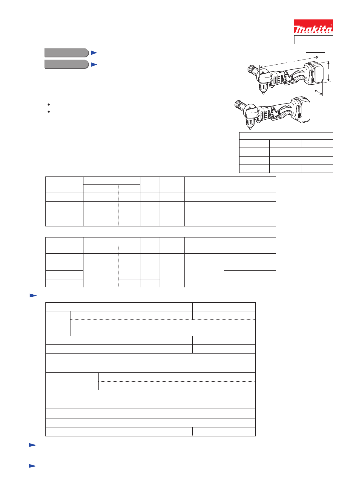
BDA341/ BDA351
14.4V/18V Cordless Angle Drill 10mm (3/8")
Battery
Capacity of drill chuck: mm (")
Capacity: mm (")
Electric brake
Variable speed control
Reverse switch
Steel
Wood
No load speed: min-1=rpm
Cell
Voltage: V
Capacity: Ah
Net weight: kg (lbs)
*with Battery BL1430
**with Battery BL1830
Max output: W
Li-ion
14.4
Model BDA341
18
BDA351
3.0
Yes
Yes
Yes
LED job light Yes
1.6 (3.5)* 1.7 (3.7)**
10 (3/8)
25 (1)
0 - 1,800 0 - 1,700
1.5 (1/16) - 10 (3/8)
Drill chuck type Keyless, Single sleeve
230 280
Models BDA341 and BDA351 have been developed as the DC version tools
of Model DA3011F, featuring:
Lightweight design obtained by using Li-ion battery as a power unit
High power 4-pole motor for excellent drilling performance
Sister tools featuring Keyed drill chuck are also available
as Models BDA340/ BDA350.
(See Technical Information of BDA340/ BDA350 for detailed information.)
Dimensions: mm (")
Width (W)
Height (H)
Length (L) 326 (12-7/8)
BDA341 BDA351
79 (3-1/8)
97 (3-13/16) 115 (4-1/2)
These products are available in the following variations.
BDA341Z No
Model No.
type quantity
Charger
Charger
---No
Battery
No
BDA341
DC18RA
BDA341RF 1
Plastic carrying
case
BDA341RFE
2
BL1430
(Li-ion 3.0Ah)
Yes
No
Battery
cover
Battery
cover
No
1
Offered to
Offered to
All countries
All countries except
North America
North America
W
H
L
BDA341
BDA351
BDA341
BDA351Z No
Model No.
type quantity
---No
Battery
No
BDA351
DC18RA
BDA351RF 1
Plastic carrying
case
BDA351RFE
2
BL1830
(Li-ion 3.0Ah)
Yes
No
No
1
All countries
All countries except
North America
North America
BDA351
Standard equipment
Optional accessories
Note: The standard equipment for the tool shown above may differ by country.
Side grip ........... 1
Battery BL1430 (for BDA341)
Battery BL1830 (for BDA351)
Drill bits for wood
Drill bits for steel
Charger DC24SA (for North America only)
Charger DC24SC (except for North America)
Fast charger DC18RA
Belt clip
Page 2
P 2/ 8
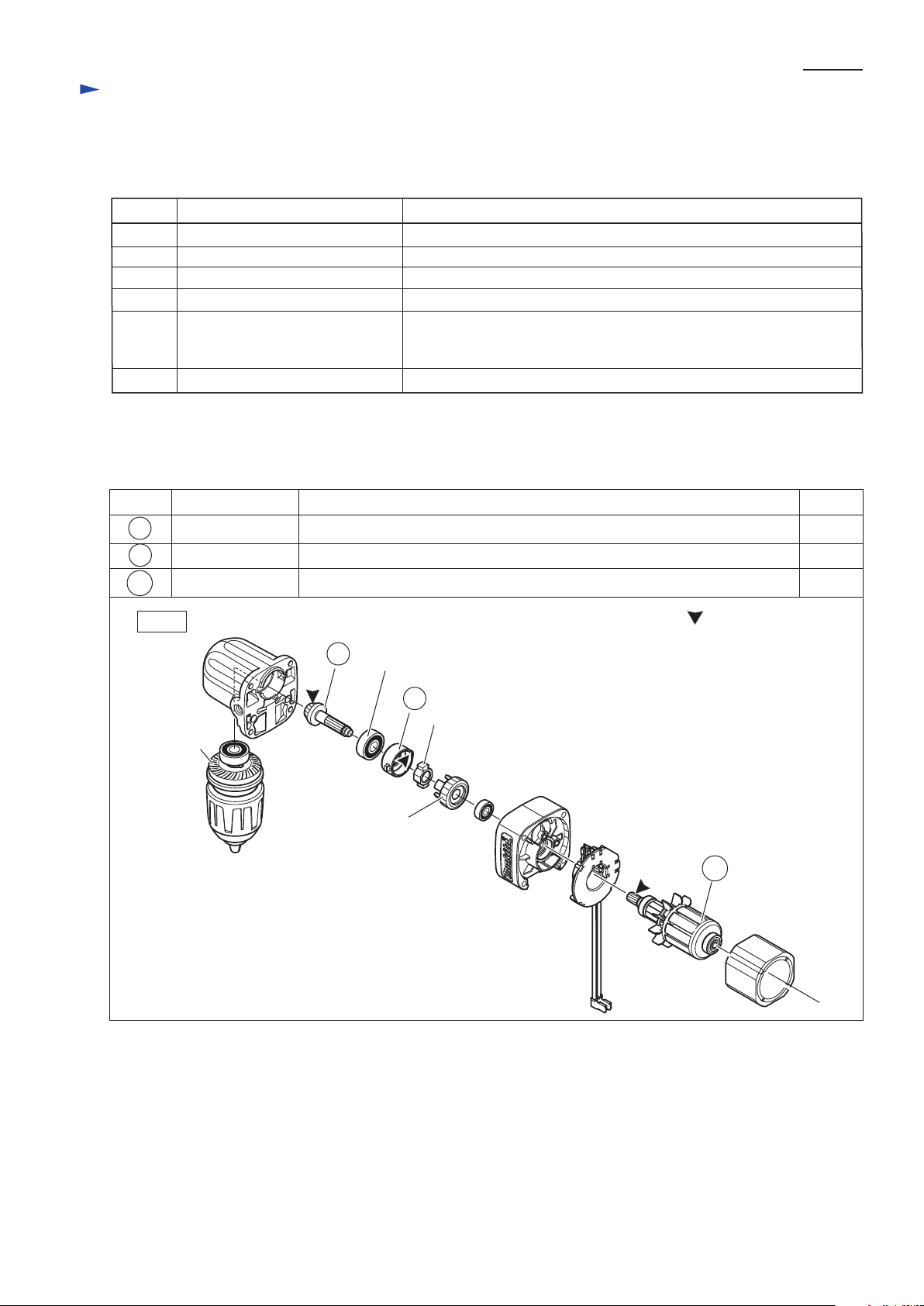
[2] LUBRICATION
Apply Makita grease N. No.2 to the following portions designated with the black triangle to protect parts and product
from unusual abrasion.
[1] NECESSARY REPAIRING TOOLS
CAUTION: Remove the bit and the battery from the machine for safety before
repair/ maintenance in accordance with the instruction manual!
Repair
Description
Assembling / Disassembling Bearing retainer 36-43
Assembling / Disassembling Bearing retainer 36-43
Assembling Spur gear 29 section to Gear housing
Removing Keyless drill chuck
Removing Ball bearings
Removing Retaining ring S-12
Code No.
Bearing setting pipe 23-15.2
1R029
Drill chuck extractor
1R139
Bearing extractor
1R269
Retaining ring S and R pliers
1R291
Wrench for Bearing retainer
(with expanded claw distance from
30mm to 36mm)
1R292
Adjustable bearing retainer wrench
1R316
Use for
Makita grease N No. 2
Fig. 1
Item No. Description Amount
4g
2g
Spiral bevel gear 9 Teeth portion for smooth engaging with Spiral bevel gear 26
Ball bearing 608ZZ
Lock cam
Spur gear 29
Spiral bevel
gear 26
Portion to lubricate
Lock ring a littleInside where Lock cam contacts
Armature Drive end where engages with Spur gear 29
15
3
5
15
3
5
Page 3
P 3/ 8
R
epair
[3] DISASSEMBLY/ASSEMBLY
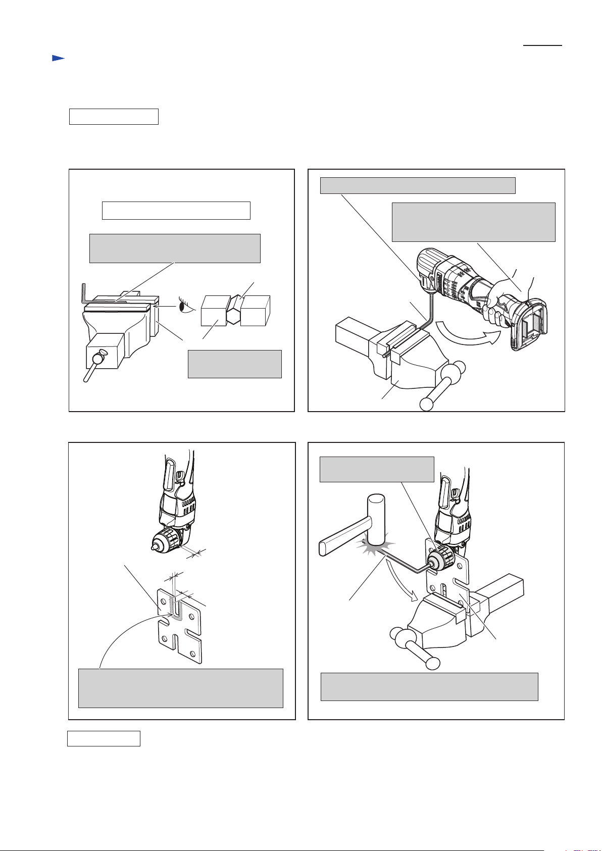
[3]-1. Keyless Drill Chuck
DISASSEMBLING
Correct setting of Hex Wrench 8
Clamp the long portion of Hex wrench 8
when using vise.
Remove Keyless drill chuck as illustrated in Figs. 2 and 3. If it is difficult to remove in this way, Keyless drill chuck
can be removed as illustrated in Figs.2A and 3A.
Hex wrench 8
Clamp the flat surface
of Hex wrench 8.
Vise
Hex wrench 8
Hex wrench 8
1. Hold Hex wrench 8 with Keyless drill chuck.
2. Firmly gripping the body in the near
of Terminal, turn the machine
counterclockwise.
Fig. 2 Fig. 3
Fig. 2A Fig. 3A
Vise
1R139 modified
as shown in Fig. 2A
1R139
(1) Do the reverse of the disassembling steps. Refer to Figs. 3 and 2., or Figs. 3A and 2A.
(2) Turn the machine or Hex wrench clockwise to tighten Keyless drill chuck. The fastening torque for Drill chuck is
40 - 45 N.m.
14mm
width groove
Make the thickness of this portion thin to 2.5mm
by grinding in order to insert 1R139 into the gap
between chuck and Gear housing.
2.5mm in thickness
Gap between
Keyless drill chuck
and Gear housing
1. Hold Hex wrench 8
with Keyless drill chuck.
2. Turn Hex wrench 8 counterclockwise by striking
with Hammer.
ASSEMBLING
Note: Keyless drill chuck may further turn resisting shaft lock mechanism, while sounding like clutch in work.
This phenomenon does not show any trouble, but Keyless drill chuck is tightened firmly.
Page 4

P 4/ 8
R
epair
DISASSEMBLING
Fig. 6 Fig. 7 Fig. 8
Fig. 9 Fig. 10
[3]-2 Spiral Bevel Gear 26
(1) Remove Keyless drill chuck as illustrated in Figs. 2 and 3 / Figs. 2A and 3A. And disassemble Bearing retainer as
illustrated in Figs. 4 and 5.
(2) Disassemble Spiral bevel gear 26 in the order of Figs. 6to 10.
Remove Gear section by striking
the edge of Gear housing.
Remove Bearing box from
Spindle.
Bearing box can be removed
by hand.
Spiral bevel gear 26
Bearing box
Spindle
Spindle
Ball bearing
6001DDW
Ball bearing
608ZZ
Ball bearing 608ZZ
Retaining
ring S-12
1R269
Bearing box
Spiral bevel
gear 26
Spiral bevel
gear 26
Spiral bevel gear 26 can
be removed by hand.
Then remove Key 4.
Remove Retaining ring S-12
with 1R291.
Remove Ball bearing 608ZZ
with 1R269.
Retaining ring S-12
Key 4
Key 4
1R291
ASSEMBLING
Do the reverse of the disassembling steps.
Note: Do not forget to assemble Key 4 to Spindle. Refer to Fig. 10.
To fit 1R292 to the notch of Bearing
retainer, enlarge this width from 30mm
to 36mm by grinding 1R292.
1R292
notch for fitting
1R292
Bearing retainer
Clamp the machine
with vise.
Remove Bearing retainer 36-43 with 1R292
by turning it clockwise.
1R292
Bearing retainer 36-43
Fig. 4
Fig. 5
Page 5

P 5/ 8
ASSEMBLING
Refer to Figs. 11 to 13.
R
epair
[3]-3. Spur Gear 29, Spiral Bevel Gear 9
4x45 tapping screw (4pcs.)
1R269
Gear housing
Disassemble Gear housing together with
Gear housing cover from Motor housing
by unscrewing 4x45 Tapping screw.
Disassemble Ball bearing
696ZZ from the shaft of
Spiral bevel gear 9 with 1R269.
Remove Gear housing cover
from Gear housing by pulling
off.
Strike the edge of Gear housing
with plastic hammer.
Gear section can be removed
from Gear housing.
Gasket
Motor housing
Gear housing cover
cut
groove of spline
Ring spring 6
Insert the pick between the groove of spline and the near point to
Ring spring’s cut. And Lever up Ring spring with the pick
Ball bearing 696ZZ
Spur gear 29
Spiral bevel
gear 9
Ball bearing
608ZZ
Gear housing cover
Gear housing
Gear section
Fig. 11
Fig. 12
Fig. 13
Lock ring
Lock cam
Pin 3.5
Lock ring
Spur gear 29
Spur gear 29
Strike the work table with
shaft end of Spiral bevel
gear 9.
Spur gear 29 can be disassembled
from the shaft of Spiral bevel
gear 9.
Separate Lock ring
from Spur gear 29.
Lock cam and Pin 3.5 can be
removed from Spur gear 29.
ASSEMBLING
Fig. 15
Fig. 14
Note: Ring Spring 6 has got wider than the size it
was, due to the disassembling step. Therefore,
Correct the size and form by pressing it with
pliers after assembling to the shaft of Spiral
bevel gear 9.
(1) Take the reverse of the disassembling steps. Refer to Figs. 13 and 12, Pay attention to Fig. 14.
(2) Mount the Gear section to Gear housing as illustrated in Fig. 15.
(3) Assemble Gear housing and Gear housing cover to Motor housing by screwing 4x45 Tapping screws. (Fig. 11)
notch
notch
protrusion
1R029
Spur gear 29
Ring spring 6
Ball bearing 696ZZ
Correct the size and form
of Ring ring 6 by pressing
the portions designated in
black arrows.
Shaft of Spiral bevel gear 9
Gear housing
Gear housing
cover
Gasket
Do not forget to mount
Gasket between Gear
housing cover and Gear
housing.
Assemble the Gear section by
pressing spur gear 29 with
1R029, while aligning the
protrusions of Lock ring to
the notches of Gear housing.
Page 6

P 6/ 8
R
epair
[3] DISASSEMBLY/ASSEMBLY
[3]-4. Motor Section
DISASSEMBLING
(1) Disassemble Gear housing and Gear housing cover from Motor housing by unscrewing 4x45 Tapping screws. (Fig. 11)
(2) Remove Motor section from Housing set (L) in the order of Figs.16 and 17.
(3) When removing Armature from Brush holder, take the steps illustrated in Figs. 18, 19 and 20.
3x16 Tapping screw (5pcs.) Housing set (R)
Separate Housing set (R)
from Housing set (L) by
unscrewing 3x16 Tapping
screws.
Yoke
unit
Motor Section
Armature
Switch lever
Remove Switch lever and Link.
Link
Fig. 16
Fig. 17
Shift the tail of Torsion spring from top of Carbon brush
to the notch of Brush holder. Now Carbon brush is free
from the pressure of Torsion spring.
tail of Torsion spring
notch
notch
Torsion spring
Carbon brush
Carbon brush
Tail of Torsion spring
Carbon brush
Carbon brush
Disconnect Carbon brush from
the commutator of Armature by
pulling up.
Then disssemble Armature and
Yoke unit from Brush holder.
Armature
Armature
Pull off Armature from
Yoke unit.
Yoke unit
Yoke unit
Fig. 18
Fig. 19 Fig. 20
Brush holder complete
Remove York unit, Brush holder complete
and Armature in a set when removing
Motor section.
Brush holder
Page 7

P 7/ 8
R
epair
[3] DISASSEMBLY/ASSEMBLY
[3]-4. Motor Section (cont.)
ASSEMBLING
Heat sink
Yoke unit
Brush holder
Armature
Protrusion for fitting to
the notch of Yoke unit
notch for fitting
to Housing set (L)
Fitting the notch of Yoke unit to the protrusion of Housing set (L),
assemble the Motor section.
Notch of
Yoke unit
Notch of
Yoke unit
(1) Assemble Armature as illustrated in Fig. 21R.
Note: Pay attention to the position of notch of Yoke unit.
It has to be located on the opposite side of Commutator.
(2) Assemble Brush holder to Armature’s Commutator end.
However, still keep Carbon brush free from the pressure of
Torsion spring of Brush holder in this step.
(2) Assemble the Motor section to Housing set (L) as illustrated
in Figs. 22 and 23.
Commutator
of Armature
Commutator
of Armature
Correct Wrong
Fig. 21R
Fig. 22 Fig. 23
Fig. 21F
Switch side
Housing set (L)
Motor Section
Housing
set (R)
Housing
set (L)
Carbon brush
Brush
holder
complete
Mount Brush holder complete on
Commutator so that the angle of two
Carbon brushes can be 90 degrees as
illustrated above.
90 degrees
[3]-5. Assembling F/R Change Lever
[3]-6. Disassembling Terminal
Protrusion of Switch
for fitting F/R Change
Lever’s concave
Concave of F/R change lever
for fitting to protrusion of
Switch
FET
Fix F/R Change lever to Switch as illustrated in Fig. 24.
Fig. 24
Fig. 25
Stopper
(for firm connection of Flag Terminal)
1. While pushing Stopper with thin screwdriver,
hitch the Flag terminal with the screwdriver.
Flag terminal
Flag terminal for this product is equipped with Stopper for firm connection. Remove Flag terminal as illustrated in Fig. 25.
2. Pull off the Flag terminal.
Page 8

P 8/ 8
Circuit diagram
White
Red
When connecting Lead wires of Brush holder
complete to Switch, connect them as follows.
* Lead wire (black) to M2 Terminal
* Lead wire (red) to M1 Terminal
Terminal
Switch
Switch lever side
LED circuit
FET
Fig. D-1
Connector of
LED circuit
Connector of
Switch
Color index of lead wires' sheath
Black
Wiring diagram
LED circuit has to be put into Housing set (L)
as illustrated below.
Lead wires of LED Circuit has to be guided in Housing set (L)
as illustrated below, and fix them with Lead wire holders.
Connector of LED circuit is connected with
Connector of Switch in the next step.
Lead wire holders
Wiring of LED Circuit
(before setting Switch and other electrical Parts)
Wiring after setting Switch and other electrical parts
Terminal
Switch
Yoke unit
FET Brush holder completeHeat sink
Lead wire holders
Put the extra portion of
Lead wires in this place.
Fix the Lead wires of Connectors
with these Lead wire holders.
Put the extra portion of
Lead wires in this place.
Connector of
Switch side
Connector of
LED side
Armature
Fig. D-2
Fig. D-3
Brush holder complete
Fix Lead wires of Brush holder complete with these Lead wire holders. And put the Lead
wires of Brush holder complete in the position illustrated above, expanding them between
York unit and Brush holder complete.
 Loading...