

Instruction Manual
Manuel d’instructions
Manual de instrucciones
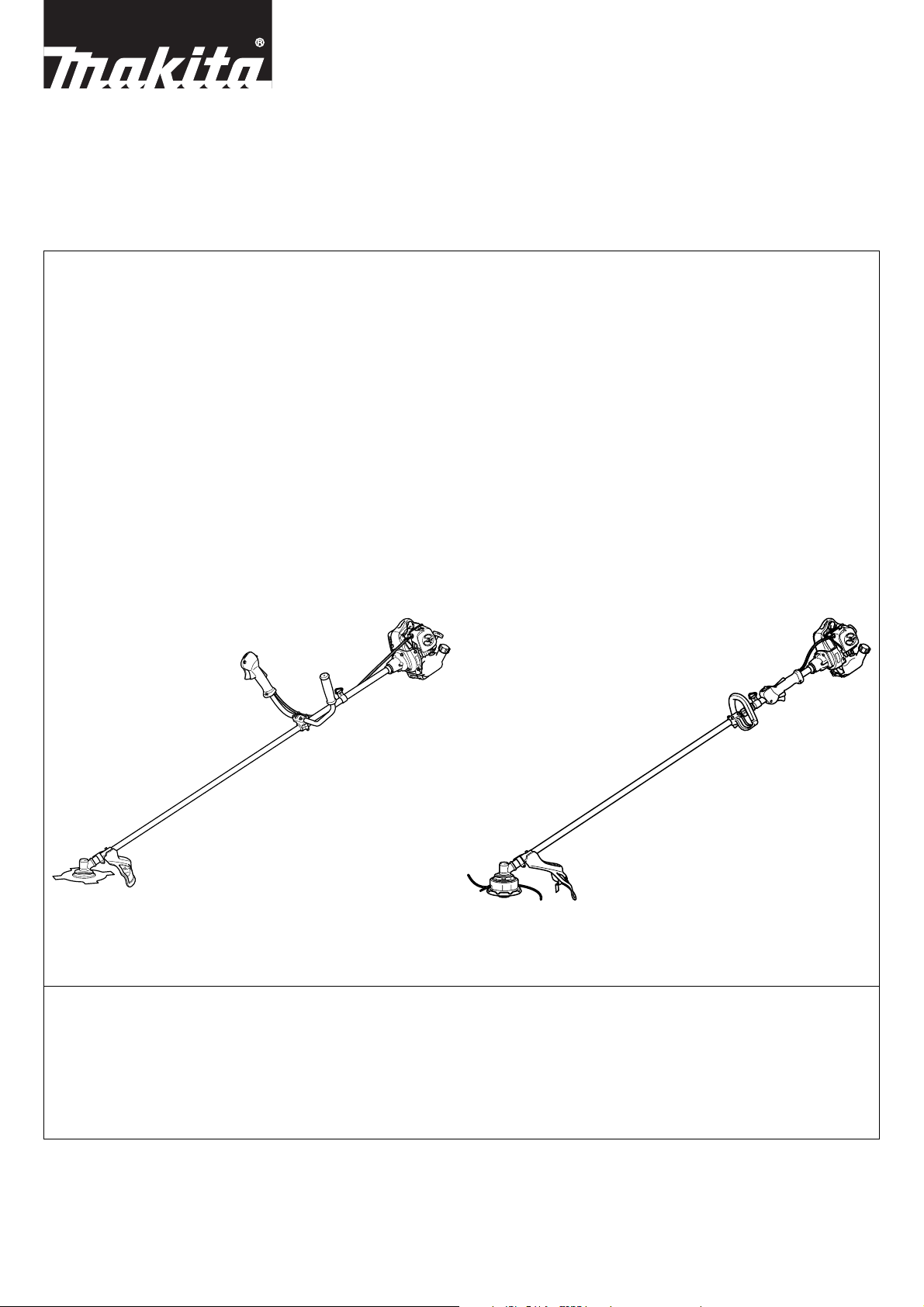
Brush Cutter
Débroussailleuse
Desbrozadora
BCM2600
BCM3300
String Trimmer
Taille-bordures
Cortabordes
BCM2310 BCM2310CA
BCM2610 BCM2610CA
BCM3310 BCM3310CA
Important:
Read this instruction manual carefully before putting the Brush Cutter / String Trimmer into operation and strictly observe the safety regulation!
Preserve instruction manual carefully !
Recommandation importante :
Lire soigneusement ce manuel d’instructions avant de mettre la débroussail leuse/t aille-bor dure s en service et observer rigou reu sement les consignes de sécurité!
Conserver soigneusement ce manuel d’instructions.
Importante:
Leer cuidadosamente este manual de instrucciones antes de poner en marcha la máquina y observar estrictamente las normes de seguridad.
Conservar este manual de instrucciones con cuidado.

ENGLISH
Thank you very much for purchasing MAKITA Brush Cutter/String T rimmer .
We are pleased to recommend to you the MAKITA Brush Cutter/String
Trimmer which is the result of a long development program and many
years of knowledge and experience. Please read this booklet which refers
in detail to the various points that will demonstrate its outstanding performance. This will assist you to obtain the best possible result from your
MAKITA Brush Cutter/String Trimmer.
Table of contents
SYMBOLS................................................................................................. 4
SAFETY INSTRUCTIONS.........................................................................5
TECHNICAL DATA............................................ ............................. ............7
MOUNTING OF HANDLE ........... ............................. .............................. ... 8
MOUNTING OF PRO TE C TOR.............................................. ............... ..... 8
MOUNTING OF CUTTER BLADE OR NYLON CUTTING HEAD............. 9
FUELS/REFUELING............................................................................... 10
CORRECT HANDLING OF MACHINE....................................................10
POINTS IN OPERATION AND HOW TO STOP......................................11
RE-SHARPENING THE CUTTING TOOL...............................................11
SERVICING INSTRUCTIONS................................................................. 12
STORAGE ............................................................................................... 13
– CALIFORNIA ONLY –
MAKITA U.S.A. Inc. (Makita) and the California Air Resources Board
emission control system’s warranty statements (owner’s defect warranty rights and obliga tions)
In the interest of the environment, Makita engines that meet strict
emission requirements are labeled. “This small off-road engine conforms to 2000 and later California Emission Control Regulations”.
CALIFORNIA EMISSION CONTROL W ARRANTY STATEMENT
YOUR WARRANTY RIGHTS AND OBLIGATIONS
The California Air Resources Board and Makita are pleased to explain
the emission control system warranty on your small off-road engine.
In California, new small off-road engine must be designed, built and
equipped to meet the state’s stringent anti-smog standards. Makita
must warrant the emission control system on your engine for the
periods of time listed below provided there has been no abuse,
neglect or improper m a intenance of your small of f- road engine.
Your emission control system includes parts such as the carburetor,
air cleaner, ignition system, fuel tank, muffler and catalytic converter.
Also included may be connectors and other emission related assemblies.
Where a warrantable condition exists, Makita will repair your small
off-road engine at no cost to you including diagnosis, parts and
labor.
MAKITA U.S.A. Inc. Warranty Coverage
The emission control system is warranted for two years. If any covered part on your engine is defective, the part will be repaired or
replaced by Makita.
Owner’s Warranty Responsibilities
As the small off-road engine owner, you are responsible for performance of the required maintenance listed in your Owner's Manual.
Makita recommends that you retain all receipts covering maintenance on your small off-road engine, but Makita cannot deny warranty solely for the lack of receipts or for your failure to ensure the
performance of all sc heduled maintenance.
As the small off-road engine owner, you should however be aware
that Makita may deny you warranty coverage if your small off-road
engine or a part has failed due to abuse, neglect or improper maintenance or unproved m odifications.
You are responsible for presenting your small off-road engine to an
authorized service dealer or equipment manufacturer to w hom Makita would sell engines as soon as the problem exists. The warranty
repairs should be completed in a reasonable amount of time, not to
exceed 30days. If you have a question regardi ng you r warranty co verage, you should contact :
* For the nearest Makita service center, please visit
www.makitatools.com
* For technical support or questions regarding operation of our tools
and accessories call: 1-800-4-MAKITA
* Makita USA Inc. Corporate Office : 14930 Northam St. La Mirada, CA
90638-5753
MAKITA U.S.A. Inc. Emission Control Defects Warranty
Provisions
The following are specific provisions relative to your Emission Control Defects Warranty Coverage. It is in addition to the Makita engine
warranty for non-regulated engines found in the Owner’s Manual.
1. Warranted Parts
Coverage under this warranty extends only to the parts listed below
(the emission control systems parts) to the extent these parts were
present on the engine purchased.
• Fuel Metering Systems
• Carburetor And Internal Parts
• Cold Start Enrichment System (Soft Choke)
• Fuel Filter (up until the first scheduled change)
• Fuel Inlet Hose
• Fuel Outlet Hose
• Air Induction System
• Air Filter (E le ment)
• Ignition System
• Spark Plug(s)
• Magneto Ignition System
•Fuel Tank
• Catalyst Or Thermal Reacter System
• Catalystic Converter
2. Length of Coverage
Makita warrants to the initial owner and each subsequent purchaser
that the warranted parts shall be free f rom defects in materials and
workmanship which cause the failure of the w arranted part(s) for a
period of two years from the date the engine is delivered to a retail
purchaser.
3. No Charge
Repair or replacement of any warranted part will be performed at no
charge to the owner, including diagnostic labor which leads to the
determination that a warranted part is defective, if the diagnostic
work is performed at an authorized service dealer of equipment manufacturer to whom Makita would sell engines.
4. Claims and Coverage Exclusions
Warranty claims shall be filled in accordance with the provisions of
the Makita engine warranty policy. Warranty coverage shall be
excluded for failures of warranted parts which are not original Makita
parts or because of abuse, neglect or improper maintenance as set
forth in the Makita engine warranty policy. Makita is not liable to
cover failures or warranted parts caused by the use of add-on, nonoriginal, or modified pa rts.
2

5. Maintenance
Any warranted part which is not scheduled for replacement as
required maintenance or which is scheduled only for regular inspection to the effect of “repair or replace as necessary” shall be warranted as to defects for the warranty period. Any warranted part
which is scheduled for replacement as required maintenance shall be
warranted as to defects only for the period of time up to the first
scheduled replacement for that part. Any replacement part that is
equivalent in performance and durability may be used in the performance of any maintenance or repairs. The owner is responsible for
the performance of all re quir ed maint enan ce, as define d in the Mak ita
owner’s manual.
6. Consequential Coverage
Coverage hereunder shall extend to the failure of any engine components caused by the failure of any warranted part still under warranty.
EMISSIONS COMPONENT DEFECT WARRANTY COVERAGE
MAKITA U.S.A. Inc. (MAKITA) warrant to the initial retail purchaser
and each subsequent owner, that this utility equipment was
designed, built, and equipped to conform at the time of initial sale to
all applicable regulations of the U.S. Environmental Protection
Agency (EPA), and that the engine is free of defects in materials and
workmanship which would cause this engine to fail to conform with
EPA regulations during its war r a nty period.
For the components listed under PARTS COVERED, the service
dealer authorized by MAKITA will, at no cost to you, make the necessary diagnosis, repair, or replacement necessary to ensure that the
engine complies with applicable U.S. EPA regulations.
EMISSISON COMPONENT DEFECT WARRANTY PERIOD
The warranty period for this engine begins on the date of sale to th e
initial purchaser and continues for a period of 2 years.
PARTS COVERED
Listed below are the parts covered by the Emission Components
Defect Warranty. Some of the parts listed below may require scheduled maintenance and are warranted up to the first scheduled
replacement point for that part.
(1) Fuel Metering System
(i) Carburetor and internal parts
(ii) Fuel filter, if applicable.
(iii) T hrottle stopp e r, if applic able.
(iv) Choke System, if applicable.
(2) Air Induction Sy s tem
(i) Air cleaner plate
(ii) Air cleaner case
(3) Ignition System
(i) Spark pl u gs .
(ii) Flywheel Magneto
(iii) Ignition Coil.
(4) Miscellaneous Items Used in Above Systems
(i) Fuel hoses, clamps and sealing gaskets
OBTAINING WARRANTY SERVICE
To obtain warranty service, take your engine to the nearest MAKITA
Factory Service Center or service Center authorized by MAKITA.
Bring your sales receipts indicating date of purchase for this engine.
The dealer of service authorized by MAKITA will perform the necessary repairs or adjustments within a reasonable amount of time and
furnish you with a copy of the repair order. All parts and accessories
replaced under this warranty become the property of MAKITA.
WHAT IS NOT COVERED
• Conditions resulting from tampering, misuse, improper adjustment
(unless they were made by the service dealer authorized by MAKIT A
during a warranty repair), alteration, accident, failure to use the recommended fuel and oil, or not performing required maintenance
services.
- The replacement parts used for required maintenance services.
- Consequential damages such as loss of time, inconvenience,
loss of use of the engine or equipment, etc.
- Diagnosis and inspection charges that do not result in warranty-eligible service being performed.
- Any non-authorized replacement part, or malfunction of authorized parts due to use of non-authorized parts.
OWNER’S WARRANTY RESPONSIBILITIES
As the engine owner, you are responsible for the performance of the
required maintenance listed in your owner's manual. MAKITA recommends that you retain all receipts covering maintenance on your
engine, but MAKITA cannot deny warranty solely for the lack of
receipts or for your failure to ensure the performance of all scheduled maintenance. As the engine owner, you should however be
aware that MAKITA may deny warranty coverage if your engine or a
part has failed due to abuse, neglect, improper maintenance or unapproved modifications.
You are responsible for presenting your engine to the nearest service
dealer authorized by MAKITA when a problem exists.
If you have any questions regarding your warranty rights and responsibilities, you should contact the followings :
* F or the nearest Makita service center, please visit
www.makitatools.com
* For technical support or questions regarding operation of our tools
and accessories call: 1-800-4-MAKITA
* Makita USA Inc. Corporate Office : 14930 Northam St. La Mirada, CA
90638-5753
(For Canada)
* F or the authorized service centre nearest you please refer to the
local yellow pa ge s di r e c tory under “tools”, or contact our c us tomer
service department Tel 1-800-263-3734 (Canada o nly), or visit our
web site www.makita .ca
* Makita Canada Inc. Head Office & Plant : 1950 Forbes Street,
Whitby, ON L1N 7B7
THINGS YOU SHOULD KNOW ABOU T THE EMISSION
CONTROL SYSTEM WARRANTY:
MAINTENANCE AND REPAIRS
You are responsible for the proper maintenance of the engine. You
should keep all receipts and maintenance records covering the performance of regular maintenance in the event questions arise.
These receipts and maintenance records should be transferred to
each subsequent owner of the engine. MAKITA reserves the right to
deny warranty coverage if the engine has not been properly maintained. Warranty claims will not be denied, however, solely because
of the lack of required maintenance or failure to keep maintenance
records.
MAINTENANCE, REPLACEMENT OR REPAIR OF EMISSION CONTROL DEVICES AND SYSTEMS MAY BE PERFORMED BY ANY
REPAIR ESTABLISHMENT OR INDIVIDUAL; HOWEVER, WARRANTY
REPAIRS MUST BE PERFORMED BY A SERVICE DEALER AUTHORIZED BY MAKITA. THE USE OF PARTS THAT ARE NOT EQUIVALENT IN PERFORMANCE AND DURABILITY TO AUTHORIZED PARTS
MAY IMPAIR THE EFFECTIVENESS OF THE EMISSION CONTROL
SYSTEM AND MAY HAVE A BEARING ON THE OUTCOME OF A WARRANTY CLAIM.
If other than the parts authorized by MAKITA are used for maintenance replacements or for the repair of components affecting emission control, you should assure yourself that such parts are
warranted by their manufacturer to be equivalent to the parts authorized by MAKITA in their performance and durability.
HOW TO MAKE A CLAIM
All repair qualifying under this limited warranty must be performed
by a service dealer authorized by MAKITA. In the event that any emission-related part is found to be defective during the warranty period,
you shall notify MAKITA at the following contacts and you will be
advised of the appropriate warranty service dealer or service providers where the warranty repair can be performed.
* For the nearest Makita service center , please visit
www.makitatools.com
* For technical support or questions regarding operation of our tools
and accessories call: 1-800-4-MAKITA
* Makita USA Inc. Corporate Office : 14930 Northam St. La Mirada, CA
90638-5753
(For Canada)
* F or the authorized service centre nearest you please refer to the
local yellow pa ge s di r e c tory under “tools”, or contact our c us tomer
service department Tel 1-800-263-3734 (Canada o nly), or visit our
web site www.makita .ca
* Makita Canada Inc. Head Office & Plant : 1950 Forbes Street,
Whitby, ON L1N 7B7
3
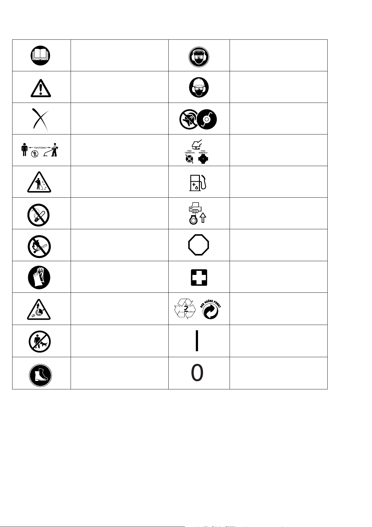
Symbols
You will note the following symbols when reading the instruction manual.
Read instruction Manual
Take Particular care and Attention
Forbidden
Keep distance Top permissible tool speed
Flying object hazard Fuel and oil mixture
No smoking Engine-Manual start
Wear eye and ear protection (for String
trimmer only)
Wear protective helmet, eye and ear
protection (for Brush Cutter only)
Do not use metal blades
(for String trimmer only)
No open flame Emergency stop
Protective gloves must be worn
Kickback Recycling
Keep the area of operation clear of all
persons and pets
Wear sturdy boots with nonslip soles.
Sleeltoed safety boots are recommended.
STOP
First Aid
RE Y
ON/STAR T
OFF/STOP
4
SAFETY INSTRUCTIONS
General Instructions
- To ensure correct operation, user has to read this instruction manual to make himself familiar with the handling of
the Brush Cutter/String Trimmer . Users insufficiently inf ormed will risk danger to themselves as well as others due
to improper handling.
- It is recommended only to lend the Brush Cutter/String Trimmer to people who have proven to be experienced
with Brush Cutter/String Trimmer. Always hand over the instruction manual.
- First users should ask th e dealer for basic instructions to familiarize oneself with the handling of an engine powered cutter.
- Children and young persons aged under 18 years must not be allowed to operate the Brush Cutter/String Trimmer. Persons over the age of 16 years may however use the device for the purpose of being trained only whilst
under supervision of a qualified trainer.
- Use Brush Cutter/String Trimmer with the utmost care and attention.
- Operate the Brush Cutter/String Trimmers only if you are in good physical condition. Perform all work calmly and
carefully. The user has to accept liability for others.
- Never use the Brush Cutter/String Trimmer after consumption of alcohol or drugs, or if feeling tired or ill.
Intended use of the machine
The Brush Cutter/String Trimmer is only intended for cutting grass, weeds, bushes, undergrowth. It should not be
used for any other purpose such as edging or hedge cutting as this may cause injury.
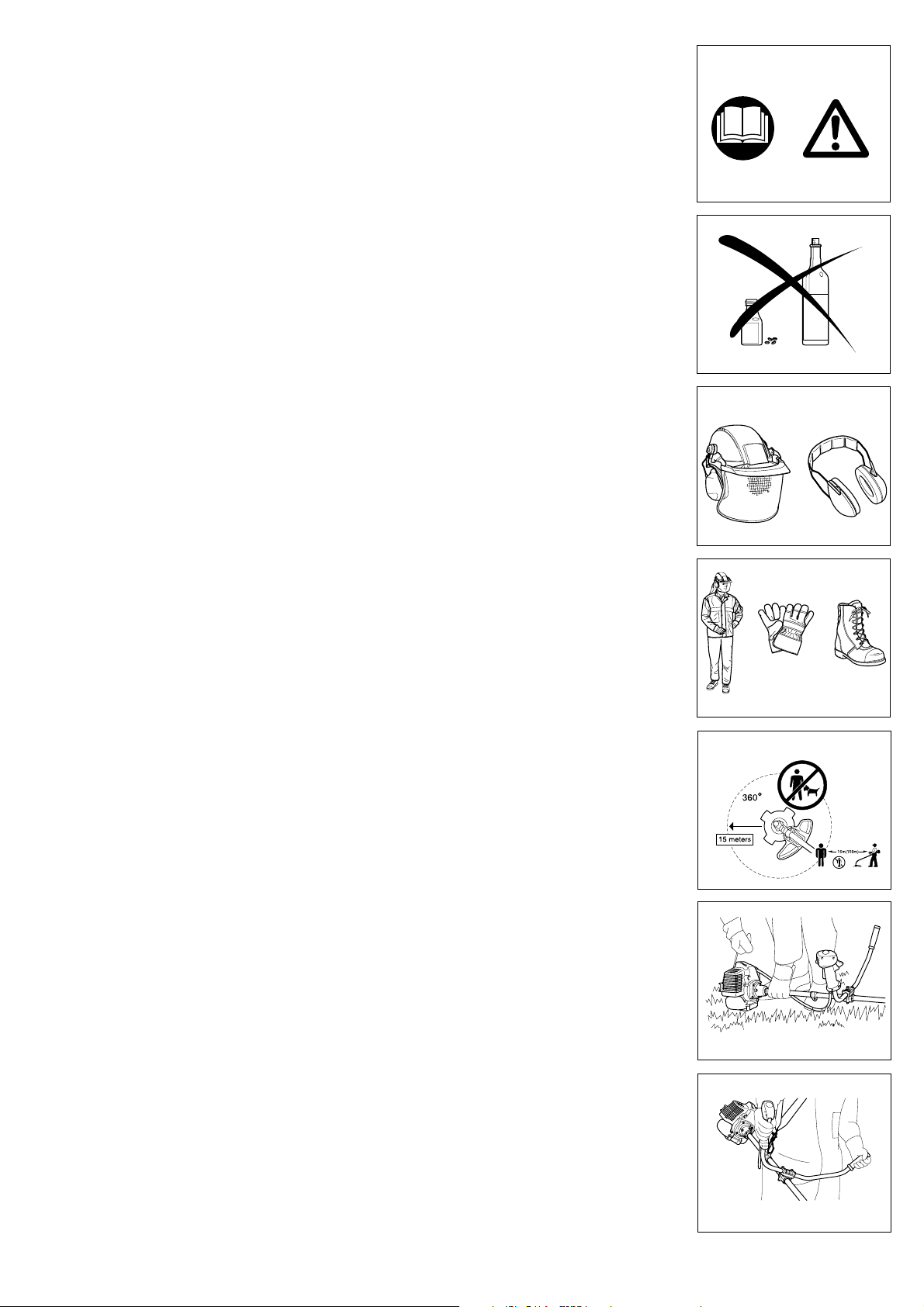
Personal protective equipment
- The clothing worn should be functional and appropr iate, i.e. it should be tight-fitting but not cause hindrance. Do
not wear either jewelry or clothing which could become entangled with bushes or shrubs.
- In order to avoid either head-, eye-, hand-or foot injuries as well as to protect your hearing, the following protective
equipment and protective clothing must be used during operation of the Brush Cutter/String Trimmer.
- Always wear a helmet where there is a risk of falling objects . The protective helmet (1) is to be checked at regular
intervals for damage and is to be replaced at the latest after 5 years. Use only approved protective helmets.
- The visor (2) of t he helmet ( or goggles ) protects the face from flying debris and s tones. During operation of the
Brush Cutter/Sting Trimmer, always wear goggles, or a visor to protect eye injuries.
- Wear adequate noise protection equipment to avoid hearing impairment ( ear muffs (3), ear plugs etc. ).
- The work overalls (4) protect against flying stones and debris. Wearing work overalls is strongly recommended.
- Always wear special gloves (5) made of thick leather during operation of the Brush cutter/String Tr immer.
- When using the Brush Cutter/Str ing Trimmer, always wear sturdy shoes (6) with a non-slip sole to protect against
injuries and ensure a good footing.
Starting the brush cutter
- Make sure that there are no children or other people wit hin a working range of 15 meters ( 50ft ), also pay attention to any animals in the working vicinity.
- Before use, always check that the Brush cutter/String Trimmer is safe for operation.
Check the security of the cutting tool, the control lever for easy action and check for proper functioning of the control lever lock.
- Rotation of the cutting tool during idling the engine is not allowed. Check with your dealer for adjustment.
Check for clean and dry handles and test the function of the start/stop switch.
- Start the Br ush Cutter/String trimmer only in accordance with the inst ructions mentioned in this manual. Do not
use any other methods for starting the engine.
- Use the Brush Cutter/String Trimmer and the tools only for such applications as specified.
- Only start t he B r ush Cutter/String Trimmer engine after the entire assembly is done. Operation of the machine is
only permitted after all the appropriate accessories are attached.
- Before starting, make sure that the cutting tool has no contact with hard objects such as branches, stones etc. as
the cutting tool will rotate when starting.
- The engine is to be switched off immediately in case of any engine problems.
- Should the cutting tool hit stones or other hard objects, immediately stop the engine and inspect the cutting tool.
- Inspect the cutting tool at shor t regular intervals for damage ( Detect hairline cracks by means of tapping-noise
test ).
- Operate the Brush Cutter/String Trimmer only with the shoulder strap provided. It should be suitably adjusted
before using the Brush Cutter/String Trimmer. Adjust the should strap according to the user’s size to prevent
fatigue during operation. Never hold the Brush Cutter/String Trimmer with one hand during use.
- During operation always hold the Brush Cutter/String Trim mer with both hands. Always ensure a safe footing.
- Operate the Brush Cutter/String Trimmer in such a manner as to avoid inhalation of the exhaust gases. Never run
the engine in enclosed rooms ( risk of gas poisoning ). Carbon monoxide is an odorless gas.
- Switch off the engine while not in use of the Brush Cutter/String Trimmer, and place it in a safe location to prevent
danger to others or damage to the machine.
- Never put the hot Brush Cutter/String Tr imm e r on dry grass or on any combustible materials.
- The Brush Cutter/String Trimmer has to be always equipped with an appropriate guard.
- All protective installations and guards provided with the Brush Cutter/String Trimmer must be used during operation.
- Never run the engine with faulty exhaust muffler.
- Stop the engine during transport.
- During transport for long distances, the tool-protection must always be used.
- Make sure a safe position of the Brush Cutter/String Trimm er dur ing car transpor t ation to avoid fuel leakage.
- In transporting the Brush Cutter/String Trimmer, make sure that the fuel tank is completely empty.
- When unloading the Brush Cutter/String Trimmer from the truck, never drop the engine on the ground, which may
severely damage the fuel tank.
- Always lift the entire unit of the machine from the ground when moving the machine. Dragging the fuel tank is
highly dangerous and may cause damage of the tank and leakage of fuel, possibly causing fire.
1
2
4
5
Diagrammatic figure
3
6
5
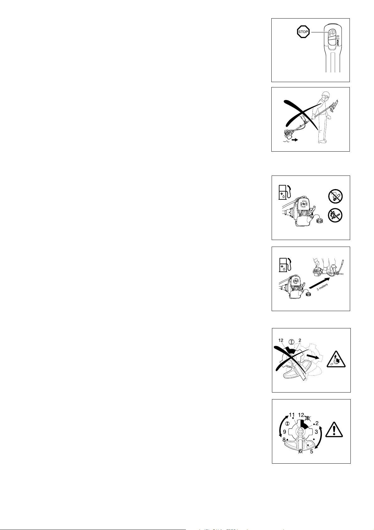
Refueling
- Always stop the engine during refueling, keep away from open flames and do not smoke.
- Always wear protective gloves during refueling. Change and clean protective clothing at regular intervals.
- Be careful not to spill either fuel or oil for environmental protection. Clean the Brush Cutter/String Trimmer immediately if fuel is split.
- Avoid any fuel contact with your clothing. Change your clothing immediately if fuel is split on it to prevent clothing
catching fire.
- Inspect the fuel cap regularly to make sure that it is securely fastened and does not leak.
- Always tighten the fuel tank cap securely. Change the location to start the engine (at least 3 meter away from the
place of refueling).
- Never refuel in closed rooms. Fuel vapors accumulate, which may cause explosions.
- Only transport and store fuel in approved containers. Make sure the fuel stored is not accessible to children.
Method of operation
- Only use the Brush Cutter/String Trimmer in good light and visibility. During the winter season, always be aware of
slippery or wet area, ice and snow. Ensure a safe footing.
- Never cut above waist height.
- Never operate the Brush Cutter/String Trimmer standing on a ladder.
- Never use the Brush Cutter/String Trimmer climbing up into trees.
- Never work on unstable surfaces.
- Remove sand, stones, nails etc. within the working range. Foreign materials may damage the cutting tool and
cause dangerous kick-back.
- The cutting tool must have reached full working speed before contact with the grass.
• Resting
• Transport
• Refuelling
• Maintenance
• Tool Replacement
Kickback
- When operating the brush cutter, uncontrollable kickback may occur.
- This is particularly the case when attempting to cut within a blade segment between 12 and 2 o’clock.
- Never use the brush cutter within a segment between 12 and 2 o’clock.
- Never apply the blade of brush cutter to solids, such as bushes and trees, etc., having a diameter in excess of
3 cm or the brush cutter will be deflected at great force with the risk of injuries.
Kickback prevention
T o avoid kickback, ensure the following :
- Operation within a blade segment between 12 and 2 o’clock presents positive hazards, especially in using metal
cutting tools.
- Cutting operations within a blade segment between 11 and 12 o’clock, and between 2 and 5 o’clock, must only be
performed by trained and experienced operators, and then only at their own risk.
Easy cutting with almost no kickback is possible within a blade segment between 8 and 11 o’clock.
Cutting Tools
Use only the correct cutting tool.
Caution:
Kickback
Diagrammatic
figure
Diagrammatic
figure
6

Maintenance instructions
- The condition of the Brush Cutter/ Str ing Trimmer must be checked before operation, in particular of the cutting tool, the protective devices and also the
shoulder strap. Special attention must be paid to the cutting blade which must be correctly sharpened.
- Stop the engine and remove spark plug connector when replacing or sharpening cutting tools, and also when cleaning the machine or cutting tool.
- Operate the Brush Cutter/String Trimmer with as little noise and contamination as possible. In particular check the correct setting of carburetor.
- Clean the Brush Cutter/String Trimmer regularly and ensure that all screws and nuts are well tightened.
- Never service or store the Brush Cutter/String Trimmer in the vicinity of naked flames.
- Always store the Brush Cutter /String Trimmer in locked rooms and with a emptied fuel tank.
- Do not perform any modifications on the Brush Cutter/String Trimmer as this will endanger your safety.
- The performance of maintenance or repair work by the user is limited to those activities as described in this instruction manual. All other works are to be
done by an Authorized Service Agent. Use only genuine spare parts and accessories supplied by MAKITA.
Use of non-approved accessories and tools means increased risk of accidents.
MAKITA will not accept any liability for accidents or damage caused by the use of non-approved cutting tools and fixing devices of cutting tools, or
accessories.
First Aid
Make sure that a first-aid box is available in the vicinity of the cutting operations in case of accident.
TECHNICAL DATA
MODEL BCM2310/CA BCM2610/CA BCM2600 BCM3310/CA BCM3300
Dry Weight 5.7 kg 5.7 kg 6.5 kg 6.5 kg 7.3 kg
Engine TLE23FD-TBM/TBD TLE26FD-TBM/TBD TLE33FD-TBM/TBD
Bore x Stroke 31 x 30 mm 33 x 30 mm 36 x 32 mm
Displacement 22.6 cm
Maximum output
Fuel Mixture of gasoline and lubricanting oil (ratio 50:1)
Lubricating oil Two-stroke motor oil FC
Fuel Tank Capacity 0.6 lit. 0.8 lit.
Spark Plug NGK BPMR8Y
Carburetor Diaphragm type (with 2 passage for air and mixture)
0.7 kW (0.94 HP)/
8000 rpm
3
0.8 kW (1.07HP)/8000 rpm 0.97 kW (1.3 HP)/7500 rpm
25.6 cm
3
32.6 cm
3
Main Pipe Drive Shaft Flex/Rigid Rigid
Diameter 7 mm Hollow (5 mm)
Upper end
Lower end
Tube Type Straight
Diameter 25.4 mm
Wall thickness 1.5 mm
Length 1500 mm
Finish Silver Anodized
Bearings Type Bronze bush in rubber
String Head Type Tap and Go
Line size 2.4 mm 2.4 mm
Gear Case Assy Arbor size M10LH FEM
Gear ratio 14/19 17/21
Clutch Case Assy Anti-Vib Yes
Number Brgs 2
Drum dia. 54 mm 78 mm
Throttle Control Overmolded Yes
First Idle Yes
Hanger Type Fixed
Guard Type Grass Weed Blade Grass Weed Blade
Swath dia 41 cm (16 in.) 43 cm (17 in.) N/A 43 cm (17 in.) N/A
Handle Assy Type Loop Bike Loop Bike
Barrier N/A
Overmolde d Yes (Black) N/A Yes (Black) N/A
Band Shoulder Type Single Double
Tool Set Yes
Blade Size
Type Quard Quard
Blade Holder N/A Yes N/A Yes
N/A
Involute Spline (7 x 7 x 0.75)
N/A
23 cm (9 in.)
Tap and Go
N/A
N/AO.Dia. 105 mm 105 mm
23 cm (9 in.)
7
MOUNTING OF HANDLE
CAUTION:
Before doing any work on the Brush Cutter/String Trimmer, always stop the engine and pull the spark plug connector off the spark plug.
Always wear protective gloves.
CAUTION:
Start the engine of Brush Cutter/String Trimmer after making sure that it is assembled completely.
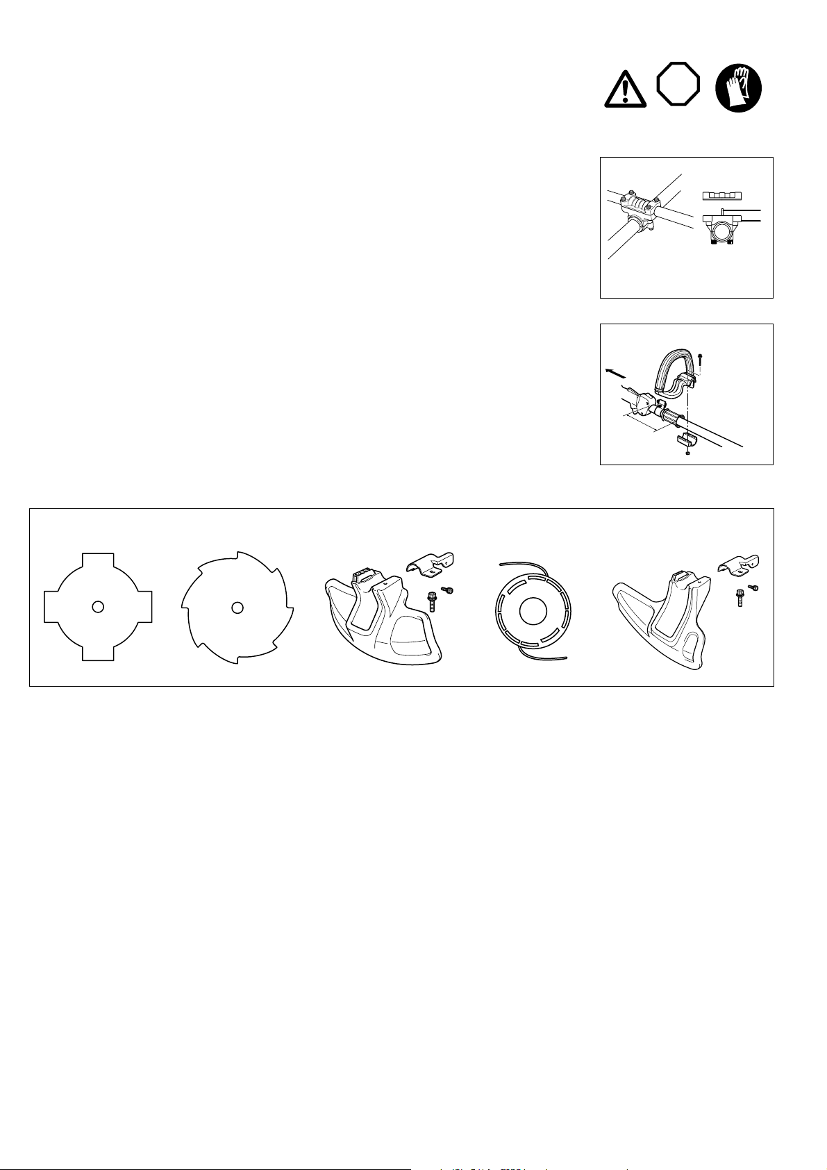
For machines with U Handle models
- Place the handle-fixing metal so that the handle with the control lever will be positioned on the right (the right-hand
grip side) as viewed from the engine side, and the other handle on the left side.
- Fit the groove of the handle-fixing material to the handle end. Fix the attached metal by he xagon sock et bolts supplied.
- Adjust the position of handle for easy and comfortable operation, and then tighten securely the four (4) hexagon
socket bolts uniformly on the right and left with the wrench provided.
For machines with Loop Handle
- Fix a barrier to the left side of the machine together with the handle of operator’s protection.
- Do not adjust position of the loop handle too close to the control grip.
- The handle must be kept in position more than 250 mm from the hanger.
MOUNTING OF PROTECTOR
To meet the applicable safety provisions, only the tool/protector combinations as described in the table must be
used.
Use genuine MAKITA cutter blades or nylon cutting head.
The cutter blade must be well sharpened, free of cracks or breakage. If the c utter blade hits against a stone during
operation, stop the engine and check the blade immediately.
STOP
BCM2600
BCM3300
to Engine
BCM2310/CA
BCM2610/CA
BCM3310/CA
Star Blade
20
Sharpen or replace the cutter blade every three (3) hours of operation.
If the nylon cutting head hits against a stone during operation, stop the engine and check the nylon cutting head immediately.
CAUTION:
The appropriate blade guard must always be installed for your own safety and complying with accident-prevention regulations.
Operation without the safety guard is not permitted.
Eddy Blade Protector for metal blades
Nylon cutting head
Protector for cord cutter
8
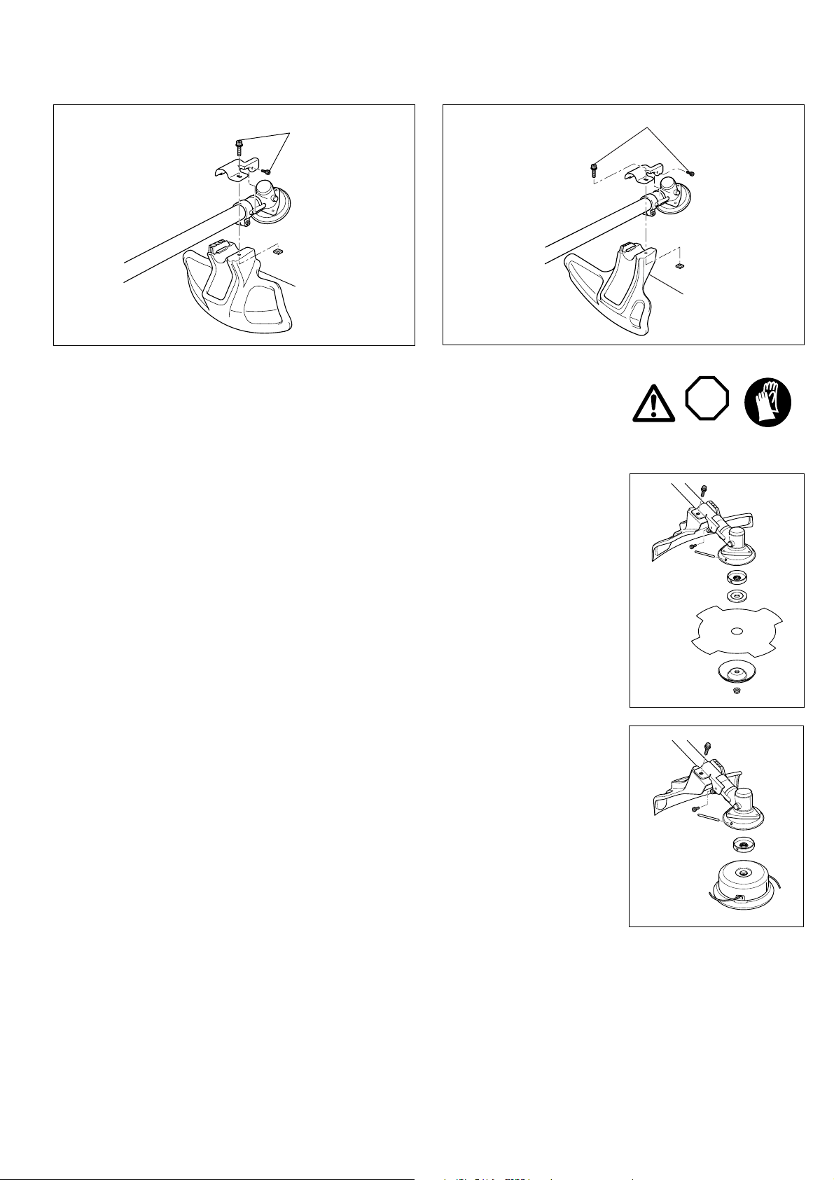
For # BCM2600 and # BCM3300
Fix the protector (1) to the clamp (3) with two bolts.
For # BCM2310/CA, BCM2610/CA and BCM3310/CA
Fix the protector (1) to the clamp (3) with two bolts.
(3)
(1)
MOUNTING OF CUTTER BLADE OR NYLON CUTTER HEAD
Turn the Brush Cutter/String Trimmer upside down and replace the cutter blade or the nylon cutting head.
- Installing Cutter-Blade
Mount the cutter blade (A) onto the receiver washer (B).
Make sure that the cutter blade (A) is centered and lies flat.
The guide of the receiver washer (B) must fit in the arbor hole in the cutter blade (A).
Install the clamp washer (C) with the raised center away from the cutter blade (A).
Insert the holding-pin (D) through t he s lot of the grass cover (E) and rotate t he rec eiver washer (B) until it is locked
with the holding -pin (D). Then install the nut guard (F) and the blade nut (G) onto the gear case and turn counterclockwise to tighten securely .
Note : Always wear gloves when handling the cutter blade
(3)
(1)
STOP
- Installing Nylon cutting head
Install the receiver washer (A) onto the gear case.
Insert the holding-pin (B) through the slot of the grass cover (C) and rotat e t he rec eiver washer (A) until it is locked
with the holding-pin (B). Then place the nylon-cutting head (D) on the receiver washer (A) and rotate the nylon-cutting head (D) counterclockwise to tighten securely.
9
FUELS/REFUELING
Handling fuel
Utmost care required when handling fuel. Fuel may contain substances similar to solvents. Refuel either in a well
ventilated room or outdoors.
Do not inhale fuel vapors, avoid any contact of fuel or oil with your skin.
Mineral oil products degrease you skin. If your skin contacts with these substances repeatedly and f or an extended
period of time, it will desiccate. Various skin diseases may result. In addition, allergic reactions may occur. Eyes
can be irritated by contact with oil. If oil comes into your eyes, immediately wash them with clear water. If your eyes
are still irritated, see a doctor immediately.
Fuel and oil mixture
This brush-cutter (string-trimm er) is powered by a high-efficiency two-stroke engine being run with a mixture of fuel
and two-stroke engine oil. The engine is designed for unleaded gasoline intended for automotive use with an
octane rating of 87 or higher.
For lubricating the engine, use any brand of premium 2-stroke engine oil classified as grade ISO-L-EGD or JSAOFC to be added to the fuel. Using any other oil will shorten the engine life and increase the required maintenance.
It is absolutely required to observe a mixture ratio of 50 : 1 (2-stroke engine oil specified above), unless otherwise
reliable function of the brush cutter ( or string trimmer ) cannot be guaranteed.
Correct Fuel Mixture ( 50 : 1 )
Gasoline Oil
1 Gallon (US) 2.6 oz.
1 Liter 20 cc ( 20ml )
5 Liter 100cc ( 100ml )
Note :
When doing the fuel-oil mixture, first mix the entire oil quantity with half of the fuel required, then add the remaining fuel. Before filling it into the brush-cutter ( string trimmer ) tank, thoroughly shake the mixture. It is not recom mended to add more engine oil than specified to ensure safe operation. This will
result in a higher production of combustion residues which will pollute the environment and clog the exhaust channel in the cylinder as well as the muffler.
In addition, the fuel consumption will rise and the performance will decrease.
Refuelling
Follow the appropriate manners described on page 6.
Storage of Fuel
Fuel cannot be stored for an unlimited period of time.
Purchase only the quantity required for a 4 week operating period. Use only approved fuel storage containers.
STOP
Observe the Safety Instructions
on page 6.
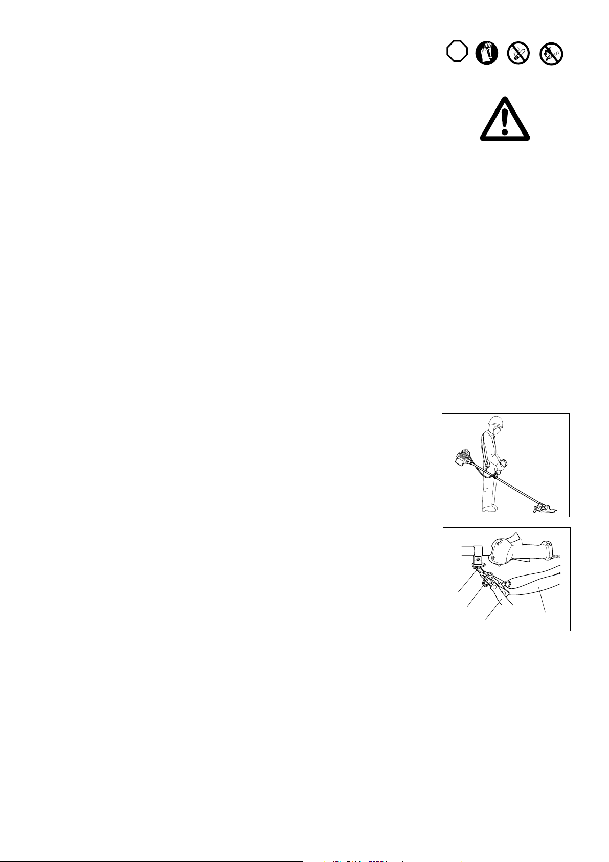
CORRECT HANDLING OF MACHINE
Attachment of shoulder strap
Always wear the shoulder strap and adjust the strap length so that the cutter blade is kept parallel with the ground.
Detachment
The shoulder strap has a quick release latch. In an emergency, pull the red strap (A) to detach the machine from
you. Be extremely careful to maintain control of the machine at this time. Do not allow the machine to be deflected
toward you or anyone in the work vicinity.
WARNING : Failure to maintain complete control of the machine may result in serious bodily injury or death.
To reassemble, remove the spring clip (B) from the machine, place open end over the strap buckle (C) and then
insert the release blade (D).
B
D
A
C
10

POINTS IN OPERATION AND HOW TO STOP
Follow the applicable accident prevention regulations.
Starting
Move at least 3 m away from the place of refueling. Place the machine on a flat, bare surface so that the cutting
blade does not contact the surface of ground or any other objects.
Cold start
For machine with U Handle or Loop Handle
- Move the switch (1) to the “I” position.
- Push gently the primer pump (A) 8 to 10 times.
- Set the choke lever (B) to the “CHOKE” position (C).
Note : Depress the trigger safety lock (E) before squeezing trigger.
- Squeeze the trigger (F) to full throttle position and hold it, and t hen s et the switch (1) to the “START” position and
release the trigger (F).
- Pull the starter until the engine tries to run (No more than 6 pulls ).
- Set the choke lever to half choke position.
- Pull the starter until the engine start running.
After the engine runs for 30 to 45 seconds at the “START” position ( for warming up the engine ), move the choke
lever to the “RUN” position ( D ).
Warm Start ( Re-starting Engine )
- Set the choke lever (B) to the “RUN” position (D).
Note : You do not need to pull the trigger or set the throttle-lock when the engine is warm.
- Pull the starter rope until the engine runs.
B
D
C
A
STOPPING
Release the trigger (F) fully, and push the switch (1) to the “O” position that the engine will stop.
Be aware that the cutting blade may not stop immediately and allow it to slow down fully.
A
IDLE SPEED ADJUSTMENT
Your M AKITA engine has been adjusted at the factory for optimum performance and fuel consumption, and no further adjustment is required.
Due to varying atmospheric and climatic conditions, however, you ma y need some minor adjustment for your area.
Checking the idle-speed
The idle-speed should be set to 2,800 – 3,300 rpm. If necessary, adjust the idle-speed using with a tachometer to insure the proper idle-speed. Note that
the cutting blade or the nylon cutting head must not turn when the engine is on idle.
Adjusting the idle rpm. Can be done by turning the idle-speed screw (A) clockwise ( for increasing the engine speed ) or counterclockwise ( for decreasing
the engine speed ).
If the engine does not idle properly after the adjustment, contact your nearest Makita dealer for service.
RE-SHARPENING THE CUTTING TOOL
CAUTION :
The cutting blades mentioned below should only be re-sharpened by an authorized facility. Manual re-shar pening
will result in imbalances of the blade causing abnormal vibrations and damage to the machine.
- Cutter Blade : star blade ( 4 teeth ), eddy blade ( 8 teeth )
An expert service for re-sharpening and balancing is provided by Authorized Service Agents.
NOTE :
To increase the service life of the above cutter blade, it may be turned over once until both cutting edges have
become blunt.
11
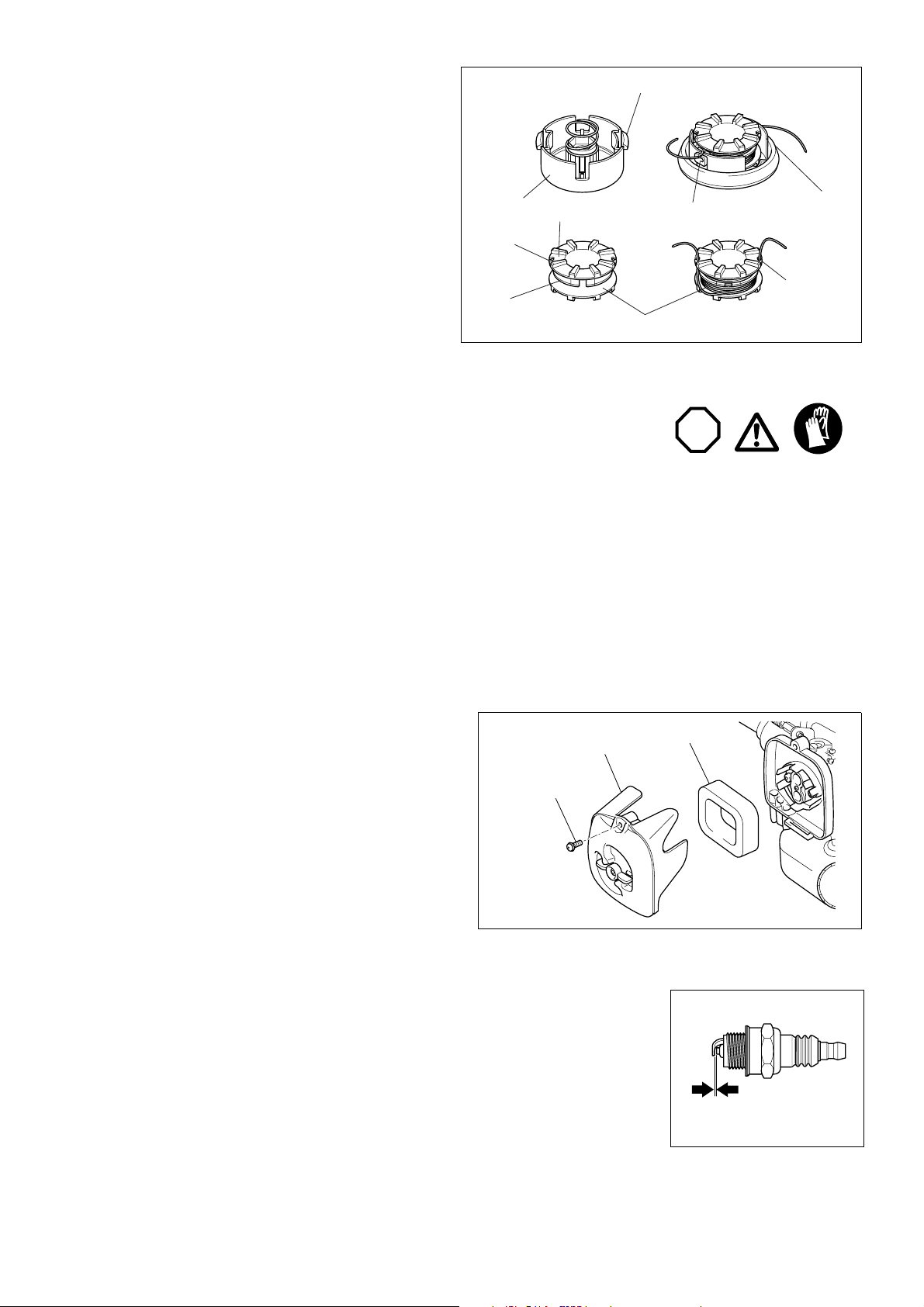
NYLON CUTTING HEAD
Replacing the nylon cord
1 First, stop the engine.
Press on the housing latches (A) inward to lift off the cover assembly (B).
Then remove the spool (D).
2 Remove any excess nylon cord from the spool.
3 Cut a length of the nylon cord that is approximately 7.5 m ( 25’ ) long.
4 Hook the center of new nylon cord into the notch (F) in the c enter of t he
spool, with one end of the cord extending about 80 mm (3” to 3-1/8”)
more than the other. Then wind both ends firmly around the spool in the
direction of the head rotation.
5 Put the cord ends temporarily into the notched (H) when w inding being
finished. Leave approximate 100 mm (4”) of the cord extended beyond
the notch.
6 Place the spool into the cover. Remove the ends of the cord from the
notches (H) and put them in the metal eyelets (I) on the cover.
7 Mount the spool ( cover-assembly ) in the housing so that the grooves
and protrusions on the spool mach up with those in the housing ( C ).
Then push the cover firmly onto the housing to secure it.
C
E
F
G
A
B
I
H
D
SERVICING INSTRUCTIONS
Before doing any work on the Brush Cutter/String Trimmer, always stop the engine and pull the plug cap off the
spark plug.
Always wear protective gloves.
Do not attempt to remove the recoil starter by yourself, which may cause an accident. It should be done by the
Authorized Service Agent.
To ensure a long service life and to avoid any damage to the machine, the f ollowing servicing operations should be
done at regular intervals.
Daily checkup and maintenance
Before operation, check the machine for loose screws or missing parts. Pay your special attention to the tightness of the cutting tool.
Before operation, always check for clogging of the cooling air passage and the cylinder fins. Clean them if necessary.
Do the following works daily after use :
- Clean the machine externally and inspect for damage.
- Clean the air filter. When working under extremely dusty conditions, clean the filter several times a day.
- Check the blade or the nylon cutting head for damage and make sure it is firmly mounted.
- Check if there is sufficient difference between idling and engagement speed. Make sure that the cutting tool does not rotate while the engine is idling.
- Check the functioning of the I-O switch, the lock-off lever, the control lever and the lock button.
Cleaning of air-filter
- Remove screw (B).
- Remove the air filter cover (A). Take out the air-filter (C) and clean it in war m
soapy water. Dry the air-filter completely.
- After cleaning, put back the air filter cover and fasten it with the screw.
Note :
If there is excessive dust or dirt adhering to the air filter, clean it every day. A
clogged air filter may make it difficult or impossible to start the engine or
increase the engine rotation-speed.
A
B
STOP
C
Checking the spark plug
Only use the supplied universal wrench to remove or install the spark plug.
The gap between the two electrodes of the spark plug should be 0.6 – 0.7 mm ( 0.024” – 0.028” ). If the gap is too
wide or too narrow, adjust it. If the spark plug is clogged with carbon or fouled, clean it completely or replace it.
CAUTION :
Never touch the spark plug connector while the engine is running ( danger of high voltage electric shock ).
12
0.6 mm – 0.7 mm
Supply of grease to gear case
Supply grease (Shell Albania 3 or equivalent ) to the gear case through the grease hole every 30 hours.
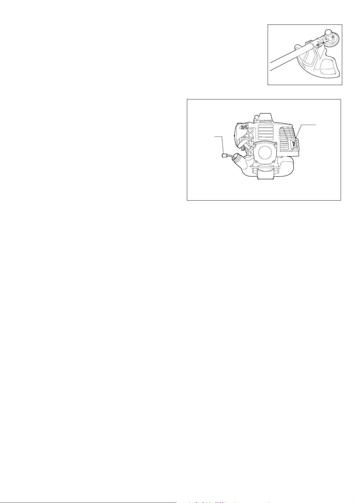
Suction head in the fuel tank
The fuel filter (A) of the suction head is for filtering the fuel to the carburetor.
A periodical visual inspection of this fuel filter is highly recommended.
To inspect the fuel filter, open the tank cap and pull out the suction head
through the opening of the tank using a wire hook.
If the filter is found to have hardened, polluted or clogged up, it should be
replaced.
Insufficient fuel supply caused by the deteriorated filter will result in the poor
performance of the engine. It is therefore important to replace the fuel filter
at least quarterly to ensure fuel-supply to the carburetor.
A
Cleaning of muffler exhaust port
Check the muffler exhaust port (B) regularly. If it is clogged by carbon
deposits, scratch out the deposits carefully with a suitable tool.
STORAGE
When the Brush Cutter/String Trimmer is in storage for a long time,
1 Drain all fuel from the fuel tank into a container approved for gasoline.
Run the engine until it stops.
2 Clean all foreign material from the machine and store it in a well-venti-
lated place that is not accessible to children.
B
13

MAINTENANCE SCHEDULE
General Engine assembly, screws and nuts Visual inspection for damage and tightness.
After each refueling Control lever
Daily Air filter
Weekly Spark plug
Quarterly Suction head
Yearly
(Long Term)
I-O switch
Cooling air duct
Cutting tool
Idling speed
Muffler
Fuel tank
Fuel tank
Carburetor
Check for general condition and security.
Functional check
Functional check
To be cleaned
To be cleaned
Check for damage and sharpness
Inspect (Cutting tool does not rotate)
Inspection, replace if necessary
Check and clean the opening if necessary
To be replace
To be cleaned
Empty fuel tank
Operate until engine stops
TROUBLESHOOTING CHART
Trouble System Observation Cause
Engine does not start or
hard to start
Warm start problem Tank filled
Engine starts but soon
stops
Insufficient performance Several systems Poor engine idling Air filter contaminated, carburetor contaminated, muffler
Ignition system Ignition spark O.K. Failure in fuel supply or compression system, mechanical defect
No ignition spark I-O switch operated, wiring fault or short circuit, spark plug or
connector defective, ignition module faulty
Fuel supply Fuel tank filled Wrong choke position, defect ive carb uretor, fuel supply line bent
or blocked, dirty fuel
Compression No compression when pulled over Cylinder bottom gasket defective, Crankshaft seals damaged,
Cylinder or piston rings defective or improper sealing of spark
plug
Mechanical fault Starter not engaging Broken starter spri ng, broken par ts inside the engine
Carburetor contaminated or damaged. Clean or replace.
Ignition spark
Fuel supply Tank filled Incorrect idle-adjustment,
Carburetor contaminated
Defective tank, fuel supply line interrupted, cable or I-O switch
defective.
clogged, exhaust duct in the cylinder clogged
14
 Loading...