

Page 1
T
ECHNICAL INFORMATION
PRODUCT
P 1/ 11
Models No.
Description
BCG140 / BCG180 (LXGC01*
Cordless Caulking Gun
*
1 Model number for North and Central American countries
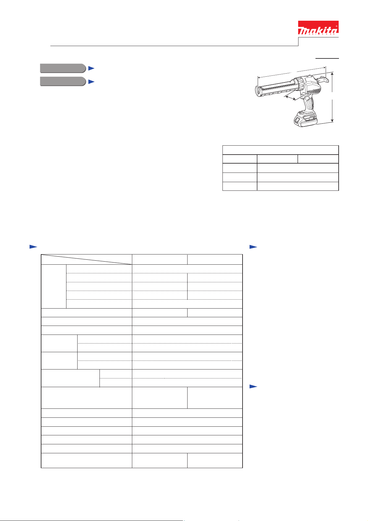
CONCEPT AND MAIN APPLICATIONS
Model BCG140 and BCG180 are Cordless Caulking Guns
powered by 14.4V/18V Li-ion battery.
They are compatible with the following sealants by changing
Holder and Piston:
• 300ml/ 600ml cartridge
• Sausage pack
• Bulk sealant
Their other main features are:
• Compact and lightweight design
• High work efficiency
• Variable speed control by dial and trigger switch
for constant bead of sealant
• Anti-drip function that stops excess sealant from oozing out
just upon release of the switch trigger
Specification
Specification
Cell Li-ion
Voltage: V
Battery
Max output: W
Max pushing force: N (lbs) 5,000 (1,100)
No load speed: mm/sec. (in/min.)
Stroke length:
mm (")
Compatible
sealant size
Variable speed control
Continuous run time (approx.) on
a single full battery charge with
300ml cartridge: cartridge quantity
Anti-drip function Yes
Overload protection function
Rubberized soft grip
Trigger lock
LED job light
Weight according to
EPTA-Procedure 01/2003: kg (lbs)
*5 for some countries only
*6 with 300ml size holder
*7 with 600ml size holder
Capacity: Ah
Energy capacity: Wh
Charging time: min.
300ml holder model 214 (8-3/4)
600ml holder model 350 (13-3/4)
300ml holder model Cartridge
600ml holder model Cartridge, Sausage pack, Bulk sealant
Model
by trigger
by dial Yes
BCG140 BCG180
14.4 18
1.3/ 3.0
19/ 44 24 (27*5)/ 54
15, 22 with DC18RC
130 150
0 - 28 (0 - 66)
Yes
180/ 410 210/ 500
Yes
Yes
Yes
Yes
2.1/ 2.2 (4.6/ 4.9)*6,
2.5/ 2.6 (5.4/ 5.8)*7
1)
(The image above is BCG180
with 300ml size holder and Battery BL1815.)
Model No.
Length (L)
Width (W)
Height (H)
*2 with 300ml size holder
*3 with 600ml size holder
*4 with 1.3Ah Li-ion battery of BL1415 or BL1815
*5 with 3.0Ah Li-ion battery of BL1430 or BL1830
1.3 (1.5*
2.1/ 2.3 (4.7/ 5.1)*6,
2.5/ 2.7 (5.5/ 6.0)*7
5)/ 3.0
L
W
Dimensions: mm (")
BCG140 BCG180
404 (15-7/8)*
264 (10-3/8)*4/ 281 (11-1/8)*5
2, 538 (21-1/4)*3
108 (4-1/4)
Standard equipment
Holder for 300ml type model
Holder for 600ml type model
Holder joint for 300ml type model
Holder joint for 600ml type model
Piston for cartridge
Piston for sausage pack
Piston for bulk sealant
Rubber ring for sausage pack
Rubber ring for bulk sealant
Nozzle for sausage pack
Nozzle for bulk sealant
Plastic carrying case or Tool bag
(for some countries only)
Note: The standard equipment
for the tool shown above
may vary by country.
Optional accessories
Li-ion battery BL1415 (for BCG140)
Li-ion battery BL1430 (for BCG140)
Li-ion battery BL1815 (for BCG180)
Li-ion battery BL1830 (for BCG180)
Fast charger DC18RC
Charger DC18SD
Charger DC24SC
Automotive charger DC18SE
Holder sets
Pistons
Rubber rings
Nozzles
Rubber seal
H
Page 2
P 2/ 11
Repair
CAUTION: Repair the machine in accordance with “Instruction manual” or “Safety instructions”.
[1] NECESSARY REPAIRING TOOLS
Code No. Description Use for
1R026 Bearing Setting Pipe 16-8.2 removing Spur gear 10
1R027
1R029
1R031
1R258 V Block setting Ball bearing 6806LLU when removing Spur gear 10
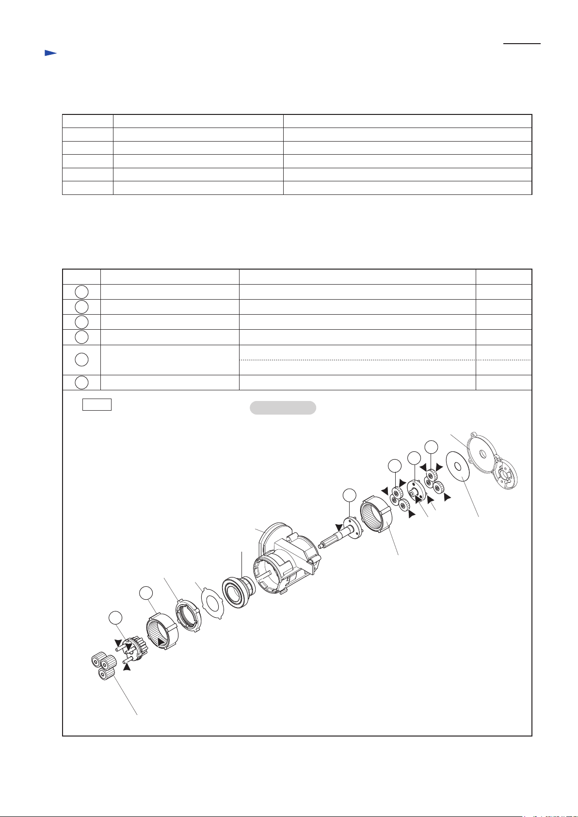
[2] LUBRICATION
Apply Seal lubricant No.101 to the following portions designated with the black triangle to protect
parts and product from unusual abrasion.
Bearing Setting Pipe 18-10.2 holding Carrier A complete when mounting 9 pcs. of Pin 3
Bearing Setting Pipe 23-15.2
Bearing Setting Pipe 28-20.2
removing Ball bearing 6803LLU
separating Spur gear 10 from Ball bearing 6806LLU
Item No.
28
32
39
41
42
43
Fig. 1
Description AmountPortion to lubricate
Carrier A complete Pin (shaft) portion for accepting Spur gear 19B
Spur gear 9C complete Drum portion where Spur gear 10 contacts
Spur gear 19A
Spur gear 9B complete
Spur gear 19A
Teeth portion
a: Pin (shaft) portion for accepting Spur gear 19A
b: Drum portion approx. 1.0 g
Teeth portion
Gear Assembly
Gear housing cover
41
39
Gear housing
Spur gear 10
Internal gear 48
Spacer
28
Plate 23
42
43
a
b
Flat washer 12
approx. 1.5 gInternal gear 48 Teeth portion
a little
a little
a little
approx. 1.0 g
approx. 1.0 g
32
Spur gear 19B
Page 3
Repair
[3] DISASSEMBLY/ASSEMBLY
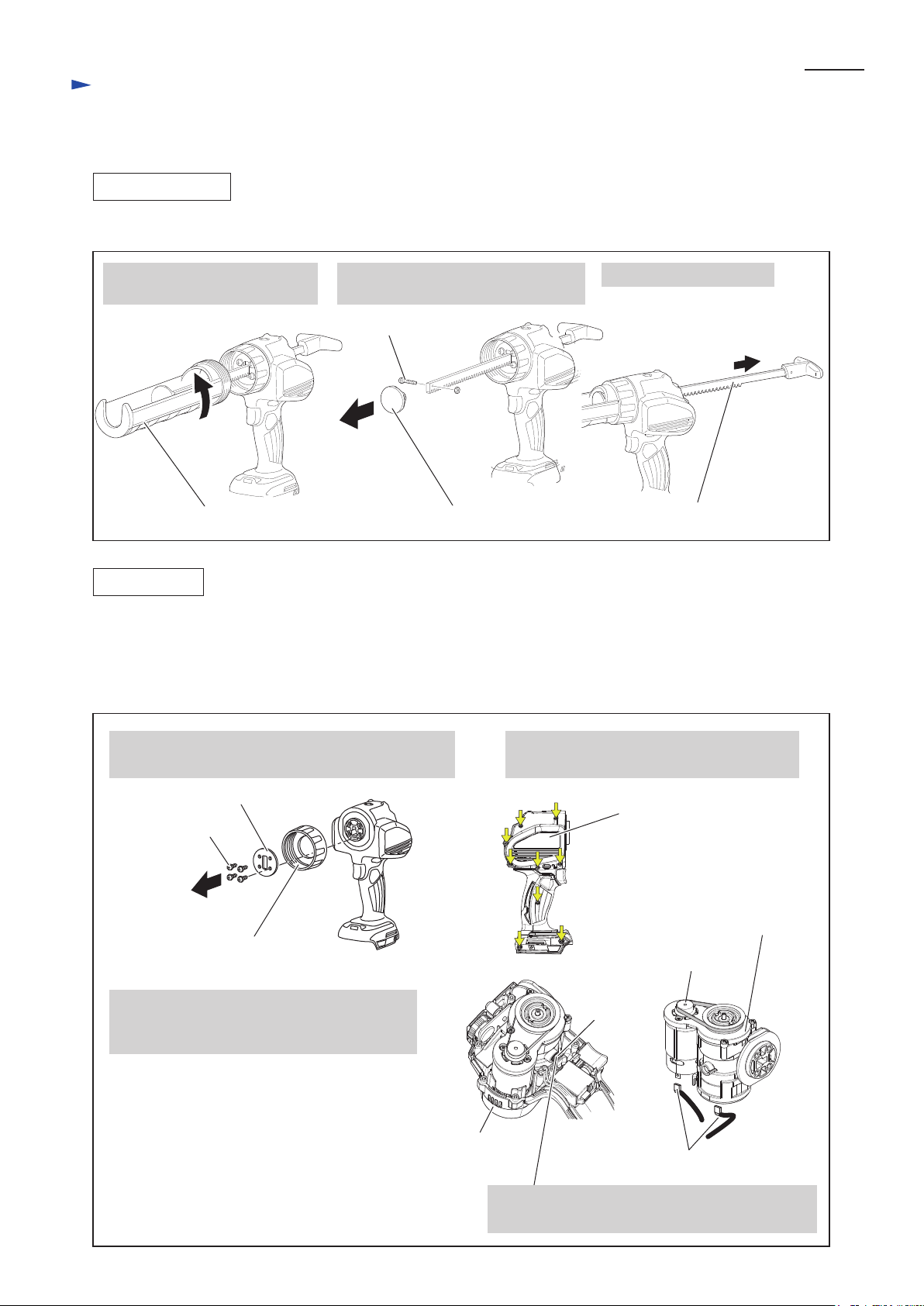
[3] -1. Rack Complete
DISASSEMBLING
Disassemble Rack complete as drawn in Fig. 2.
Fig. 2
P 3/ 11
1. Disassemble Holder complete
by turning counterclockwise.
Holder A or B complete Piston A, B or C complete Rack 42 or 64 complete
ASSEMBLING
Assemble by reversing the disassembly procedure. (Refer to Fig. 2)
2. Disassemble Piston complete by
unscrewing M3x18 Pan head screw.
M3x18 Pan head screw
3. Pull out Rack complete.
[3] -2. Motor Complete, Gear Assembly
(1) Disassemble the drive section (Gear assembly, Motor complete) as drawn in Fig. 3.
Fig. 3
1. Loosen M5x16 Pan head screws, and remove Plate
and Holder joint.
M5x16
Pan head
screw (4 pcs.)
Holder joint A or B complete
6. Separate drive section (Motor complete and
Gear assembly) from Housing (L) complete.
And disconnect receptacles from DC motor.
Plate
Housing (L) complete
2. Loosen 9 pcs. of 3x16 Tapping screw, and
remove Housing (R) complete.
Housing (R)
complete
Gear assembly
Motor
complete
Compression
spring 6
Receptacles
Note: Hold Compression spring 6 with your finger,
or it will come off.
Page 4
Repair
[3] DISASSEMBLY/ASSEMBLY
[3] -2. Motor Complete, Gear Assembly (cont.)
DISASSEMBLING
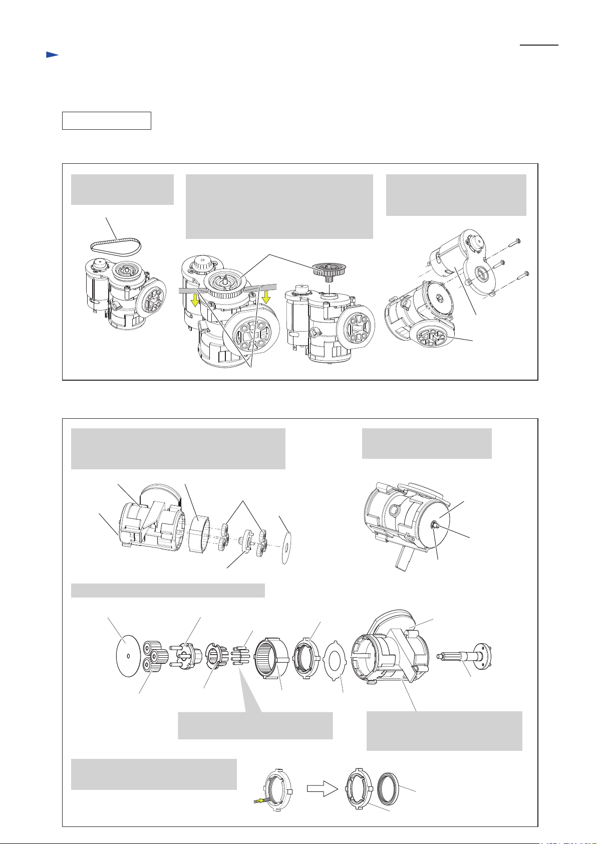
(2) Remove Motor complete from Gear assembly as drawn in Fig. 4.
Fig. 4
P 4/ 11
1. Remove Synchro belt
4-176.
Synchro belt 4-176
(3) Disassemble component parts of Gear assembly from Gear housing as drawn in Fig. 5.
Fig. 5
1. Remove Flat washer 12, Spur gear 19A (6 pcs.),
Spur gear 9B complete and Internal gear 48 from
Gear housing as shown below.
2. Remove Spur gear 9A complete from
Gear assembly by levering up with
Slotted screwdrivers.
Note: Spur gear 9A complete is assembled
at the factory, so do not disassemble it.
Spur gear 9A complete
Slotted screwdrivers
3. Remove Motor complete from
Gear assembly by loosening
three 3x16 Tapping screws.
2. Remove Stop ring E-4 from
Spur gear 9C complete.
Motor complete
Gear assembly
Gear housing
Flat
washer 5
3. Remove the following pars as shown below.
Flat washer 5
Spur gear 19B ( 3 pcs.)
Internal gear 48
Spur gear 19A (6 pcs.)
Spur gear 9B complete
Carrier A complete
Pin 3 ( 9 pcs.)
Carrier B
Note: Pin 3 comes off easily,
so be careful not to lose them.
Flat washer 12
Spacer with
Oil seal 30
Internal gear 48
Plate 23
Flat washer 5
Spur gear 9C
complete
Stop ring E-4
Gear housing
Spur gear 9C
complete
Note: Spur gear 10 and Ball bearings
still remain in Gear case
in this step.
4. Remove Oil seal 30 from the groove
on Spacer with a slotted screwdriver.
Oil seal 30
Spacer
Page 5

Repair
[3] DISASSEMBLY/ASSEMBLY
[3] -2. Motor Complete, Gear Assembly (cont.)
DISASSEMBLING
(4) Remove Spur gear 10 and Ball bearings from Gear housing as drawn in Fig. 6.
Fig. 6
P 5/ 11
1. Set 1R026 on Spur gear 10 and press 1R026 with
arbor press to remove Spur gear 10.
Spur gear 10
3. Set Ball bearing 6806LLU
with Spur gear 10 into 1R258.
Ball bearing 6806LLU
with Spur gear 10
1R258
4. Set 1R031 onto Spur gear 10 and
press the gear with Arbor press.
Arbor press
1R026
2. Spur gear 10 is removed together with
Ball bearing 6806LLU.
Spur gear 10
Note: Be sure to prevent foreign materials
from sticking to Magnet because it has
strong magnetic force.
5. Spur gear 10 is removed
from Ball bearing 6806LLU.
Ball bearing 6806LLU
1R031
Ball bearing 6806LLU
Magnet
Spur gear 10
(5) Ball bearing 6803LLU still remains in Gear housing in the step of Fig. 6. This ball bearing can be removed
as drawn in Fig. 7.
Fig. 7
1. Set 1R029 on Ball bearing 6803LLU and
press the bearing with Arbor press to remove it.
Ball bearing
6803LLU
1R029
2. The component parts of Spur gear 10 section
are removed as shown below.
Ball bearing 6803LLU,
removed in the left
Ball bearing 6806LLU,
removed in Fig. 6
Spur gear 10,
removed in Fig. 6
Page 6

Repair
[3] DISASSEMBLY/ASSEMBLY
[3] -2. Motor Complete, Gear Assembly (cont.)
ASSEMBLING
(1) Assemble Ball bearing 6803LLU to Gear housing. Refer to the drawing on the left in Fig. 7.
(2) Mount Ball bearing 6806LLU to Spur gear 10. Refer to the drawing on the bottom in Fig. 6.
(3) Assemble the Spur gear 10 section to Gear housing. Refer to the drawing on the upper right in Fig. 6.
(4) Mount Oil seal 30 to Spacer. Refer to the drawing on the bottom in Fig. 5.
(5) Assemble Plate 23, Spacer, Internal gear 48 and Spur gear 9C complete to Gear housing as drawn in Fig. 8.
Fig. 8
Note: Assemble Spacer with the convex side
of it facing to Internal gear 48.
P 6/ 11
Spacer
Internal gear 48
(6) Assemble the parts on the Flat washer 5 side to Gear housing as drawn in Fig. 9.
Fig. 9
1. Set Carrier A complete on 1R027, and
assemble Carrier B and 9 pcs. of Pin 3.
Oil seal 30
Plate 23
Pin 3 (9 pcs.)
Carrier B
Carrier A complete
1R027
Gear housing
Spur gear 9C
complete
2. While holding Internal gear 48
with your fingers, assemble Gear housing
to Carrier A complete section.
Gear housing
< Note for Assembling of Pin 3 >
Do not lubricate on Pin 3.
And, be careful that Pin 3 easily falls off.
3. Assemble Spur gear 19B to the Pins of Carrier A complete.
And then, mount Flat washer 5 to Gear housing.
Flat washer 5
Spur gear 19B
( 3 pcs.)
Pins of Carrier
A complete
4. Assemble Stop ring E-4 to the shaft
on Spur gear 9C complete.
Spur gear 9C complete
Stop ring E-4
Page 7

Repair
[3] DISASSEMBLY/ASSEMBLY
[3] -2. Motor Complete, Gear Assembly (cont.)
ASSEMBLING
(7) Assemble the parts on the Flat washer 12 side to Gear housing as drawn in Fig. 10.
Fig. 10
P 7/ 11
1. Assemble the other Internal
gear 48. And then, mount 3 pcs.
of Spur gear 19A to the three
pins of Spur gear 9C complete.
Spur gear 19A
Internal gear 48
Spur gear 9C
complete
4. Assemble Motor complete with
three 3x16 Tapping screws.
2. Assemble Spur gear 9B complete.
And then, mount the other 3 pcs. of
Spur gear 19A to the pins of Spur
gear 9B complete.
Spur gear 9B
complete
Spur gear 19A
5. Assemble Spur gear 9A complete and Synchro
belt 4-176.
3. Assemble Flat washer 12
to Gear housing.
And make sure that it fits
to Gear housing.
Flat washer 12
Motor complete
Gear assembly
Spur gear 9A
complete
Synchro belt 4-176
Page 8

Repair
[3] DISASSEMBLY/ASSEMBLY
[3] -2. Motor Complete, Gear Assembly (cont.)
ASSEMBLING
(8) Assemble the driving section (Gear assembly and Motor complete) to Housing (L) complete as drawn in Fig. 11.
Fig. 11
P 8/ 11
1. Mount Compression spring 6 to Magnet
in Gear housing.
Compression spring 6
Magnet
3. Gear assembly is pushed by Compression spring 6
toward Sub controller, and it may not be fitted
within the rib on Housing (L) complete at the motor
portion. So, push Gear assembly toward the direction
of the black arrow shown below to set it within the rib.
Rib
2. Fit Compression spring 6 to the rib on
Housing (L) complete with pressing
it toward Magnet.
Compression spring 6
Rib
Magnet
4. Make sure that Compression spring 6
fits inside the space.
Compression
spring 6
Sub controller
(9) When replacing the whole Gear assembly, use new Gear assembly as drawn in Fig. 12.
Fig. 12
1. Remove three 3x16 Tapping screws and Gear housing cover from Gear assembly.
2. Assemble Motor complete with Gear housing cover to new Gear assembly
with three 3x16 Tapping screws.
Note: Scrap Removed Gear housing cover and three 3x16 Tapping screws.
Gear housing cover
(the component of Motor complete) 3x16 Tapping screw (3 pcs.)
Main body of
Gear assembly
Motor complete
Page 9

Circuit diagram
Fig. D-1
Black
Gray
White
Sub controller
P 9/ 11
Color index of lead wires' sheath
Blue
Red
Yellow
Dial
Red point mark
DC Motor
DC motor has to be mounted so
that its Red point mark is located
to Sub controller side.
Warning lamp
Switch
LED Job light
Controller
Terminal
Page 10

Wiring diagram
Fig. D-2
Gear assembly
Lead wires have to be
fixed within Lead wire
holder.
P 10/ 11
Wiring of DC motor’s Lead wires
(Viewed from Housing (L) side)
Wire connecting
portions
Flag terminal
Red point mark
Flag terminals have to be connected so that
their wire connecting portions are faced
toward Gear assembly side.
DC motor
Flag terminal
Fig. D-3
Wiring of Lead wires of Sub Controller
(Viewed from Housing (R) side)
Sub controller
Inner wall
Rib
Lead wires of Sub controller have to be
routed between Ribs and the inner wall of
Housing (L) complete.
Housing set (L)
Page 11

Wiring diagram
Fig. D-4
Line filter
Put Line filter in this place.
(when using Line filter)
Route Sub controller’s lead wires
(black, white, red, blue) through
this Lead wire holder.
Route Sub controller’s lead wires
(black, white, red, blue) through
this Lead wire holder.
Sub controller
Rib A
Rib B
Connector
P 11/ 11
Wiring in Housing set (L)
(Viewed from Housing (R) side)
Route Sub controller’s lead
wires (black, white, red, blue)
and Controller’s lead wires to
DC Motor (black, red)
between Ribs A and B.
Switch
Lead wire holder
Route Controller’s lead wires to
DC Motor (black, red) through
this Lead wire holder.
Rib C
Do not route Connector’s
lead wires on Rib C.
Controller
Terminal
 Loading...