

Page 1
GASOLINE BLOWER
SOUFFLEUR A ESSENCE
SOPRADOR DE GASOLINA
MAKITA CA Statement
BBX7600CA
MAKITA non CA Statement
English / Français / Español
BBX7600
INSTRUCTION MANUAL
INSTRUCTIONS D’EMPLOI
INSTRUCCIONES DE MANEJO
Important:
Read this instruction manual carefully before putting the Blower into operation and
strictly observe the safety regulations! Preserve instruction manual carefully!
Importante :
Lisez attentivement ce manuel utilisateur avant de mettre en route le souffleur et
respectez scrupuleusement les consignes de sécurité.
Conservez soigneusement ce manuel.
Importante:
Lea bien este manual antes de poner el soplador en funcionamiento, y observe
estrictamente las medidas de seguridad. Conserve este manual de instrucciones.
Page 2
English
Thank you very much for selecting the Makita blower. We are pleased
to be able to offer you the Makita blower, which is the result of a long
development program and many years of knowledge and experience.
The blower models BBX7600 / BBX7600CA combines the advantages
of state-of-the-art technology with ergonomic design. They are of lightweight, handy, compact and represent professional equipment for a
great variety of applications.
Please read, understand and follow this booklet, which refers in detail
to the various points that will demonstrate its outstanding performance.
This will assist you to safety obtain the best possible results from your
Makita Blower.
Table of Contents
Symbols ............................................................................................... 2
Safety instructions............................................................................. 3-5
Technical data ...................................................................................... 6
Designation of parts ............................................................................. 7
Assembly instructions .......................................................................8-9
Before starting the engine............................................................. 10-11
Operation ......................................................................................12-13
Adjustment of idling............................................................................ 13
Operation method .............................................................................. 14
Inspection and maintenance .........................................................15-17
Storage.......................................................................................... 17-18
Troubleshooting ................................................................................. 19
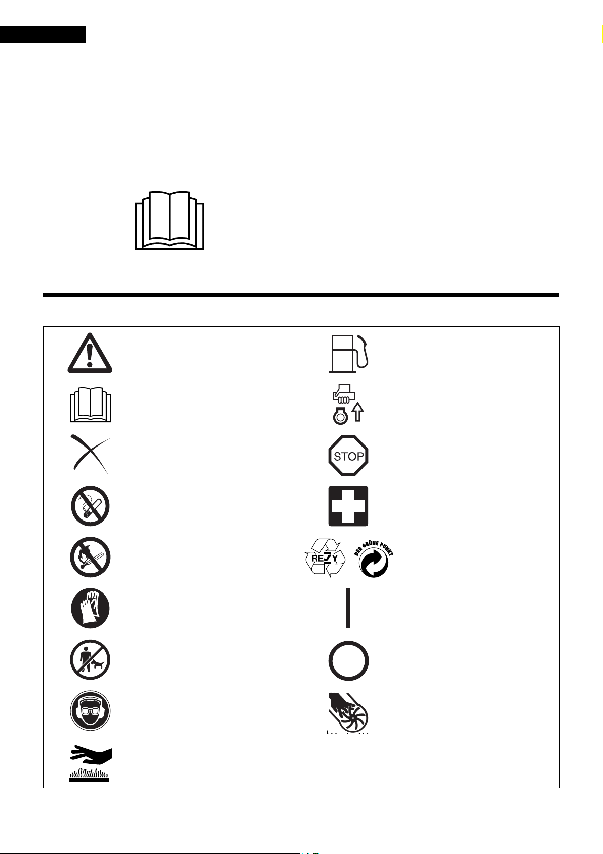
SYMBOLS
It is very important to understand the following symbols when reading this instructions manual.
Page
WARNING/DANGER Fuel (Gasoline)
Read, Understand and Follow Instruction
Manual
Forbidden Emergency Stop
No Smoking First Aid
No Open Flame Recycling
Protective Gloves must be Worn ON/START
Engine-manual Start
Keep the Area of Operation
Clear of All Persons and Pets
Wear Eye and Ear Protection
Hot surfaces - Burns to fingers or hands
OFF/STOP
Severing of fingers or hand,
impeller blade
2
Page 3
SAFETY INSTRUCTIONS
(1)
(2)
(3)
(4)
(5)
15 meters
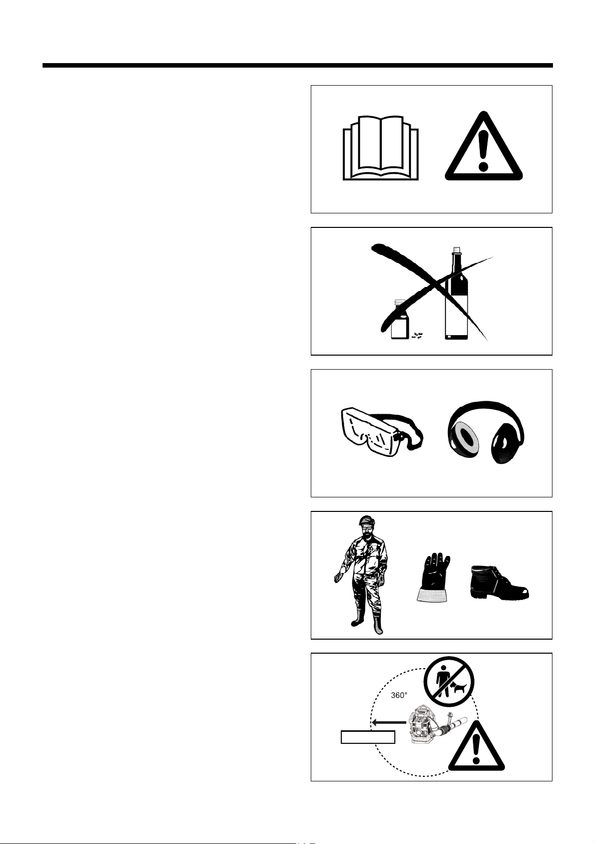
General Instructions
• To ensure correct and safe operation, the user must read, understand
and follow this instruction manual to assure familiarity with the handling
of the blower (1). Users insufficiently informed will risk danger to
themselves as well as others due to improper handling.
• It is recommended only to loan the blower to people who have proven
to be experienced with blowers.
• Always hand over the instruction manual.
• First-time users should ask the dealer for basic instructions to
familiarize oneself with the handling of a blower.
• Children and young persons aged under 18 years must not be allowed
to operate the blower. Persons over the age of 16 years may however
use the tool for the purpose of being trained only while under the direct
supervision of a qualified trainer.
• Use blowers with the utmost care and attention.
• Operate the blower only if you are in good physical condition.
• Perform all work conscientiously and carefully. The user has to accept
responsibility for others.
• Never use the blower while under the influence of alcohol or drugs (2).
• Do not use the unit when you are tired.
• Save these instructions for future referral.
Personal Protective Equipment
• The clothing worn should be functional and appropriate, I. e. It should
be tight fitting but not cause a hindrance. Do not wear jewelry, clothing
or long hair which could be drawn into the air intake.
• In order to avoid head-, eye-, hand- or foot injuries as well as to protect
your hearing the following protective equipment and protective clothing
must be used during operation of the blower.
Pay particular attention to the following regulations
• Clothing must be sturdy and snug-fitting, but allow complete freedom
of movement. Avoid loose-fitting jackets, flared or cuffed pants,
scarves, unconfined long hair or anything that could be drawn into the
air intake. Wear overalls or long pants to protect your legs.
Do not wear shorts. (4)
• Blower noise may damage your hearing. Wear sound barriers (ear
plugs or ear mufflers) to protect your hearing. Continual and regular
users should have their hearing checked regularly. (3)
• Use of gloves when working with the blower is recommended.
Wear sturdy shoes with non-slip soles. (4)
• Proper eye protection is a must. Even though the discharge is directed
away from the operator, ricochets and bounce-backs can occur during
blower operation. (3)
• Never operate a blower unless wearing goggles or properly fitted
safety glasses with adequate top and side protection which comply
with ANSI Z 87. 1 (or your applicable national standard).
Starting up the blower
• Please make sure that there are no children or other people within a
working range of 15 meters (5), also pay attention to any animals in the
working vicinity. Never use the blower in urban areas.
• Before operating, always check that the blower is safe for operation:
Check the security of the throttle lever. The throttle lever should be
checked for smooth and easy action. Check for proper functioning of
the throttle lever lock. Check for clean and dry handles and test the
function of the l-O switch. Keep handles free of oil and fuel.
3
Page 4
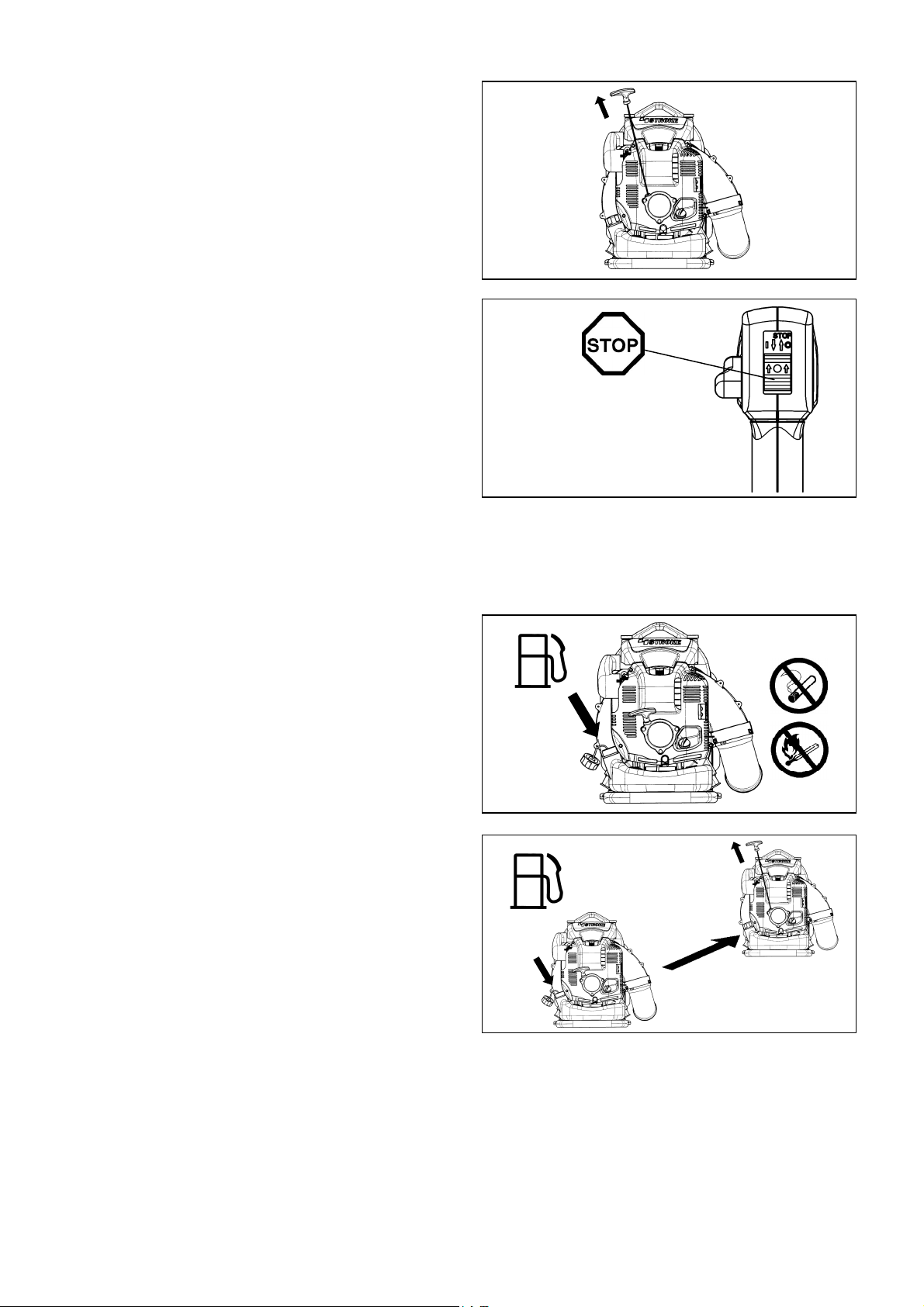
Start the Blower only in accordance with the instructions.
(6)
(7)
(8)
(9)
3 meters
• Resting
• Transport
• Refuelling
• Maintenance
• Tool Replacement
Do not use any other methods for starting the engine (6) !
• Use the blower and the tools supplied only for applications specified.
• Start the blower engine only after the entire tool has been assembled.
Operation of the tool is permitted only after all the appropriate
accessories are attached.
• The engine is to be switched off immediately if there are any engine
problems.
• When working with the blower, always wrap your fingers tightly around
the handle, keeping the control handle cradled between your thumb
and forefinger. Keep your hand in this position to have your machine
under control at all times. Make sure your control handle is in good
condition and free of moisture, pitch, oil or grease.
Always ensure a safe, well-balanced footing.
• Operate the blower in such a manner as to avoid inhalation of the
exhaust gases. Never run the engine in enclosed rooms (risk of
suffocation and gas poisoning). Carbon monoxide is an odorless gas.
Always ensure there is adequate ventilation.
• Switch off the engine when resting or leaving the blower unattended.
Place it in a safe location prevent danger to others, setting fire to
combustible materials, or damage to the machine.
• Never lay the hot blower onto dry grass or onto any combustible
materials.
• All protective parts and guards supplied with the machine must be
used during operation.
• Never operate the engine with a faulty exhaust muffler.
• Shut off the engine during transport (7).
• Position the blower safely during car or truck transportation to avoid
fuel leakage.
• When transporting the blower, ensure that the fuel tank is completely
empty.
Refuelling
• Shut off the engine during refuelling (7), keep well away from open
flame (8) and do not smoke.
• Avoid skin contact with petroleum products. Do not inhale fuel vapor.
Always wear protective gloves during refuelling. Change and clean
protective clothing at regular intervals.
• Take care not to spill either fuel or oil in order to prevent soil
contamination (environmental protection). Clean the blower
immediately after fuel has been spilt. Allow wet cloths to dry before
disposing in properly, covered container to prevent spontaneous
combustion.
• Avoid any fuel contact with your clothing. Change your clothing
immediately if fuel has been spilled on it (fire hazard).
• Inspect the fuel cap at regular intervals making sure that it stays
securely fastened.
• Carefully tighten the locking screw of the fuel tank. Change locations to
start the engine (at least 3 meters away from the place of refuelling)
(9).
• Never refuel in closed rooms. Fuel vapors accumulate at ground level
(risk of explosions)
• Only transport and store fuel in approved containers. Make sure stored
fuel is not accessible to children.
• Do not attempt to refuel a hot or a running engine.
4
Page 5
Method of operation
(10)
(11)
(12)
• Use the blower only in good light and visibility. During cold seasons
beware of slippery or wet areas, ice and snow (risk of slipping).
Always ensure a safe footing.
• Never work on unstable surfaces or steep terrain.
• To reduce the risk of personal injury, do not direct air blast towards
bystanders, since the high pressure of the air flow could injure eyes
and could blow small objects at great speed.
• Never insert any foreign object into the air intake of the machine or into
the nozzle of the blower. It will damage the fan wheel and may cause
serious injury to the operator or bystanders as a result of the object or
broken parts being thrown out at high speed.
• Pay attention to the direction of the wind, i.e., do not work against the
wind.
• To reduce the risk of stumbling and loss of control, do not walk
backward while operating the machine.
• Always shut off the engine before cleaning or servicing the unit or
replacing parts.
Maintenance instructions
• Be kind to the environment. Operate the blower with as little noise and
pollution as possible. In particular, check the correct adjustment of the
carburetor.
• Clean the blower at regular intervals and check that all screws and
nuts are securely tightened.
• Never service or store the blower in the vicinity of open flames, sparks,
etc. (11).
• Always store the blower in a well-ventilated locked room and with an
emptied fuel tank.
Observe and follow all relevant accident prevention instructions issued
by the trade associations and by insurance companies. Do not perform
any modifications to the blower as this will risk your safety.
The performance of maintenance or repair work by the user is limited to
those activities as described in this instruction manual. All other work is
to be done by Authorized Service Agents.
Use only genuine spare parts and accessories supplied by Makita.
Use of non-approved accessories and tools means increased risk of
accidents and injuries. Makita will not accept any liability for accidents or
damage caused by the use of any non-approved attachment or accessories.
First Aid
In case of accident make sure that a well-stocked first-aid kit is available
in the vicinity of the operations. Immediately replace any item taken from
the first aid kit.
When asking for help, please give the following information:
• Place of accident
• What happened
• Number of injured persons
• Extent of injuries
• Your name
Packaging
The Makita blower is delivered in a protective cardboard box to prevent
shipping damage. Cardboard is a basic raw material and is therefore
consequently reusable or suitable for recycling (waste paper recycling).
5
Page 6

TECHNICAL DATA
Model
Mass (without blower pipe) (kg) 10.2 (22.4lbs)
Dimension (without blower pipe L x W x H) (mm) 350 × 430 × 495 (13.7 × 16.9 × 19.5 in)
Max. engine speed (min
Idling speed (min
Engine displacement (mL) 75.6 (4.61 cu,in)
Fuel Automobile gasoline
Fuel tank capacity (L) 1.9 (64.2 fl.oz)
Engine oil
Engine oil volume (L) 0.22 (7.4 fl.oz)
Carburetor (Diaphragm-carburetor) WALBRO WYK
Ignition system Solid state ignition
Spark plug NGK CMR6A
Electrode gap (mm) 0.7 - 0.8 (0.028 - 0.031 in)
Noise Level (50Feet per ANSI B175-2-2000) (dB(A)) 74
Notes:
1. Use the oil and spark plug specified by Makita.
2. This specification is subject to change without prior notice.
(For Canada)
NOTE: This spark ignition system complies with the Canadian standard ICES-002.
-1
) 7,200
-1
) 2,800
SAE 10W-30 oil of API Classification, Class SF or higher
(4-stroke engine for automobile)
BBX7600
BBX7600CA
6
Page 7
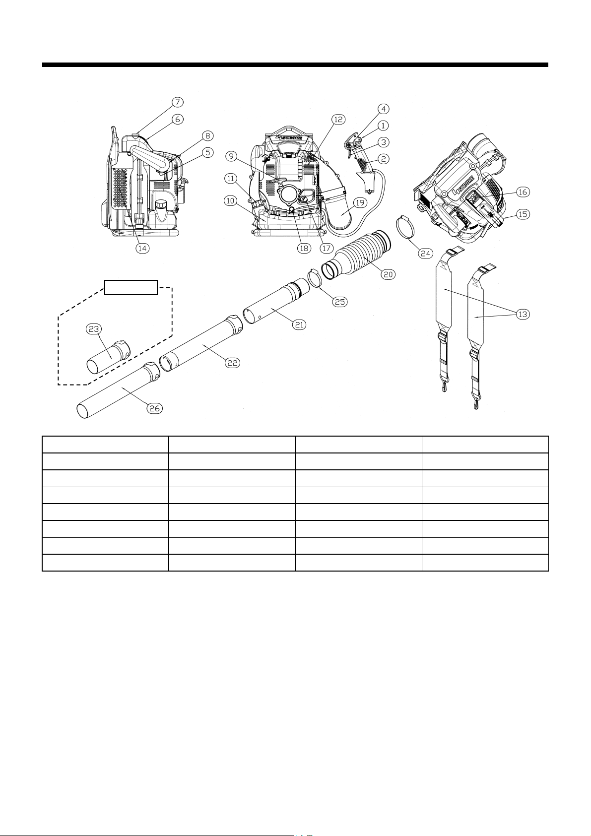
DESIGNATION OF PARTS
OPTION
DESIGNATION OF PARTS DESIGNATION OF PARTS DESIGNATION OF PARTS DESIGNATION OF PARTS
1. Stop switch 8. Choke Lever 15. Plug Cover 22. Blower Pipe
2. Control Handle 9. Starter Handle 16. Spark Plug 23. Blower Nozzle L=200
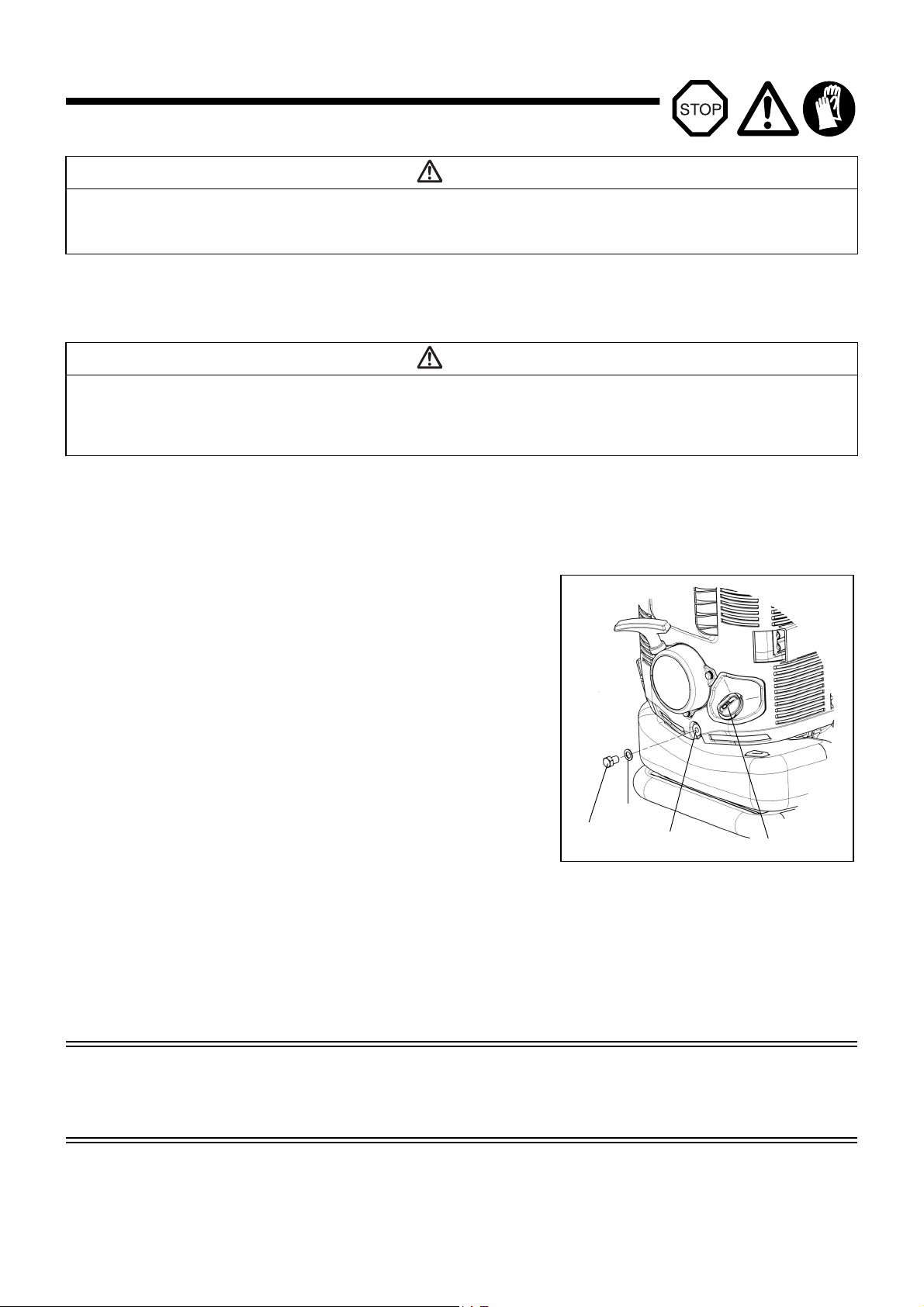
3. Trigger Lever 10. Fuel Tank 17. Oil Cap 24. Hose Band ø100
4. Cruise Control Lever 11. Fuel Tank Cap 18. Oil Drain Bolt 25. Hose Band ø76
5. Primer Pump 12. Muffler 19. Elbow 26. Blower Nozzle L=450
6. Element Cover 13. Shoulder Strap 20. Flexible Pipe
7. Knob Bolt 14. Air Inlet Net 21. Swivel Pipe
7
Page 8
ASSEMBLY INSTRUCTIONS
(5)
(4)
(1)
(2)
(3)
(6)
(7)
(8)
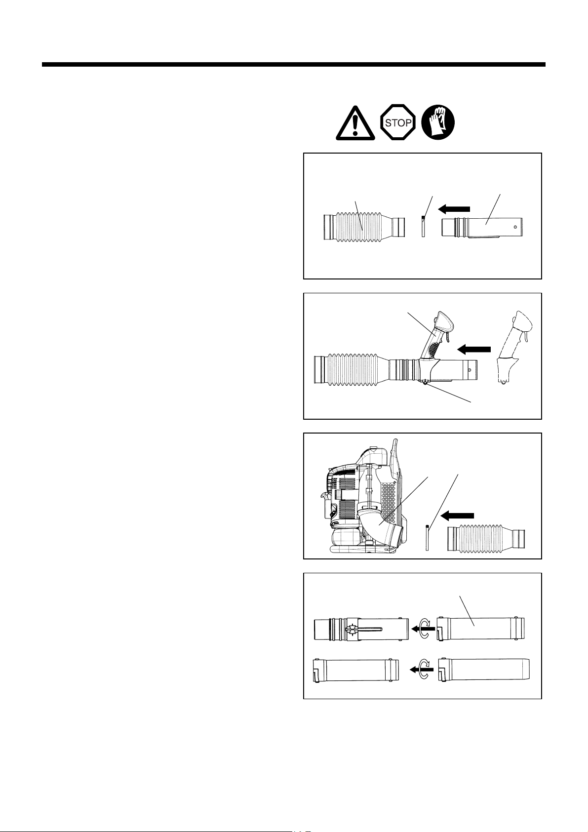
ASSEMBLY OF BLOWER PIPES
CAUTION : Before performing any work on the blower, always stop
the engine and pull the spark plug connectors off the
spark plug.
Always wear protective gloves!
CAUTION : Start the blower only after having assembled it
1. Assemble straight pipe with swivel (3) into flexible pipe (1) and
tighten hose band ø76 (2).
2. Install control handle (4) onto straight pipe with swivel and tighten
the clamp screw (5).
completely.
3. Assemble flexible pipe to elbow (6) on blower and tighten hose band
ø100 (7).
4. Assemble straight pipe (8) to straight pipe with swivel, turning
straight pipe clockwise to lock it into place.
5. Make sure all clamps are tight.
8
Page 9
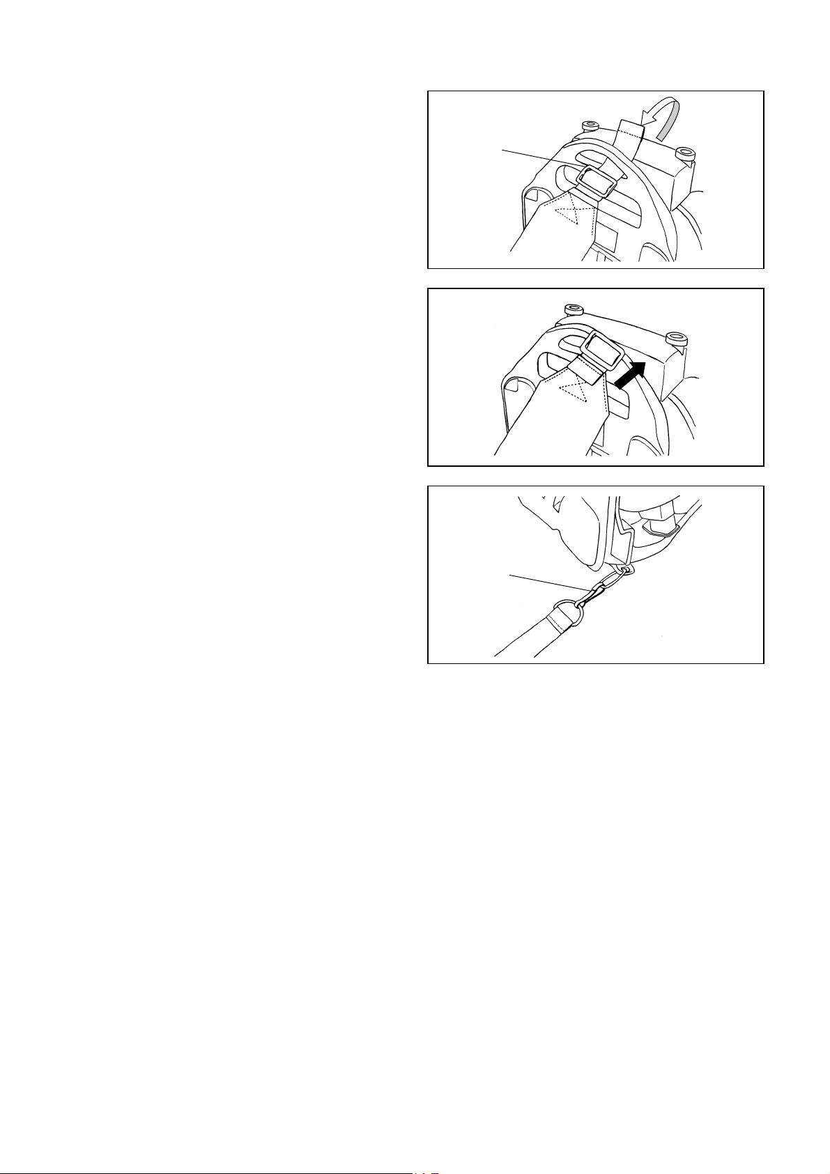
ATTACHING THE SHOULDER STRAP
(1)
Quick-disconnect
spring hook
Attachment Procedure
Attaching the shoulder strap to the blower.
• Loop the end of the strap through the lower part of the hanger as
shown in the figure at right. The side of the strap that has the folded tip
should be facing outwards. Then, bring the end of the strap back over
the hanger and thread the remaining length of the strap through the
buckle (1). Tighten the buckle (1) by pushing it towards the hanger in
the direction of the arrow shown in the drawing while pulling on the
strap in the opposite direction.
• After attaching the strap, tighten the buckle to the hanger. Tug strongly
at the strap to make sure that the strap is secure and will not come
undone.
• Attach the hook at the bottom of the shoulder strap to the ring on the
frame.
• Make sure that the strap is not twisted.
Caution: Please make sure that the strap is attached with the folded tip
facing outwards. If the strap is used with the outside of the strap
facing in, there is the risk that the strap may come loose causing the operator to drop the blower.
9
Page 10
BEFORE STARTING THE ENGINE
Upper limit
Lower limit
Oil level gauge
Remain 100 mL
1. Checking and Refilling Engine Oil
1) Follow the procedure below when the engine oil is cold i.e. the blower has
not been running.
• Inspection:Set the blower down on a level surface and remove the oil cap.
• Adding Oil:Set the blower down on a level surface and remove the oil cap.
2) On average, engine oil normally needs to be added after every 20 hours of
operation. This interval for every change in oil corresponds to refuelling the
blower approximately 10-15 times.
3) Please change the oil whenever it becomes dirty or significantly changes
color. (Refer to p.15 for the oil change procedure and frequency.)
Recommended oil: Makita genuine oil or SAE10W-30 oil of API type SF grade or better (4 stroke motor oil for automobiles)
Oil capacity: Approximately 0.22 L (220 ml)
Make sure that the oil level is within the upper and lower limit
marks on the oil level gauge. If the oil is not up to the 100mL level,
fill up with new oil.
Fill the oil up to the upper limit of the oil level gauge.
CAUTION
• If the blower is not stored in an upright position, the oil may flow from the level gauge into the engine and give a false reading when checking
the oil level. This may result in inadvertently overfilling whenever adding engine oil. Always store in an upright position.
• If the upper oil level limit is exceeded, the oil may become dirty and white smoke may appear due to burning excessive oil.
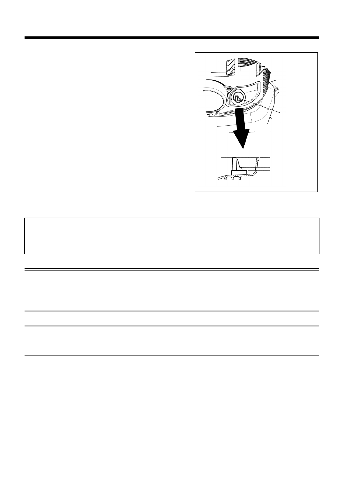
Check Point #1: The oil cap
• Wipe off dirt and grime around the opening before removing the oil cap.
• Remove the oil cap and place it on a clean surface so that it does not accumulate any sand, dirt, or other foreign materials. These may stick to
the cap and adulterate the engine oil. Dirty oil containing sand, dirt, or foreign materials may cause excessive wear on the engine due to
improper lubrication and cause a breakdown.
Check Point #2: Oil spillage
• Oil spillage on the outside on the blower may cause the engine oil becoming dirty or adulterated. Therefore, please wipe off any oil spillage
before starting the engine.
10
Page 11

2. Fuel supply
WARNING
• When refuelling the unit, be sure to observe the following instructions to prevent ignition or fire:
- Fuel supply must be made in a place free of fire. Never bring the fire (smoking, etc.) near the place of fuel supply.
- Stop the engine and allow the engine to cool down before refuelling.
- Open the fuel tank cap slowly. The fuel may be spilled out under internal pressure.
- Take care not to spill the fuel. Any spilled fuel must be wiped clean.
- Carry out fuel supply in a well-ventilated place.
• Handle the fuel with care.
- Fuel sticking to the skin or entering an eye may cause allergies or irritation. When any physical abnormality is detected, consult the medical
specialist immediately.
• DO NOT put oil in the fuel tank.
STORAGE PERIOD OF FUEL
Fuel should be used within a period of 4 weeks, even if it is kept in a special container in a well-ventilated and shaded area.
Otherwise, fuel may deteriorate in one day.
Storage of machine and refill tank
• Keep the machine and tank at a cool place free from direct sunshine.
• Never keep the fuel in a car.
FUEL
The engine is a four-stroke engine. Be sure to use an automobile gasoline (regular gasoline or premium gasoline).
Points for Fuel
• Never use a gasoline mixture which contains engine oil. Otherwise, it will cause excessive carbon accumulation or mechanical troubles.
• Use of deteriorated oil will cause irregular start-up.
When refuelling, stop the engine and wait for the engine to cool down.
REFUELLING METHOD
• Loosen the tank cap a little to release the tank pressure.
• Detach the tank cap, and refuel, discharging air by tilting the fuel tank so that the refuel port will be oriented upward. DO NOT fill fuel up to the
top of the tank.
• After refuelling, securely tighten the tank cap.
• If there is any flaw or damage on the tank cap, replace it.
• The tank cap wears out in course of time. Replace it every two to three years.
• DO NOT put fuel in the oil fill port.
11
Page 12
(2)
Stop Switch
Cruise control lever
Open
(3)
Hi-speed
Low-speed
(7)
(8)
Choke lever
Primer pump
Close
(4)
(5)
OPERATION
1. Starting
WARNING
• Never attempt engine start in a place where the fuel has been supplied.
- It may cause ignition or fire. When starting the engine, keep a distance of at least 3 m.
• Exhaust gas from the engine is toxic. Do not operate the engine in a poorly-ventilated place, such as in a tunnel, building, etc.
- Operating the engine in the poorly-ventilated place may cause poisoning by exhaust gas.
• In case of detection of any abnormality in sound, odor, vibration after starting, stop the engine immediately and carry out inspection.
- If the engine is operated without attending such abnormality, an accident may occur.
• Make sure that the engine stops when the stop switch is set to “O” position.
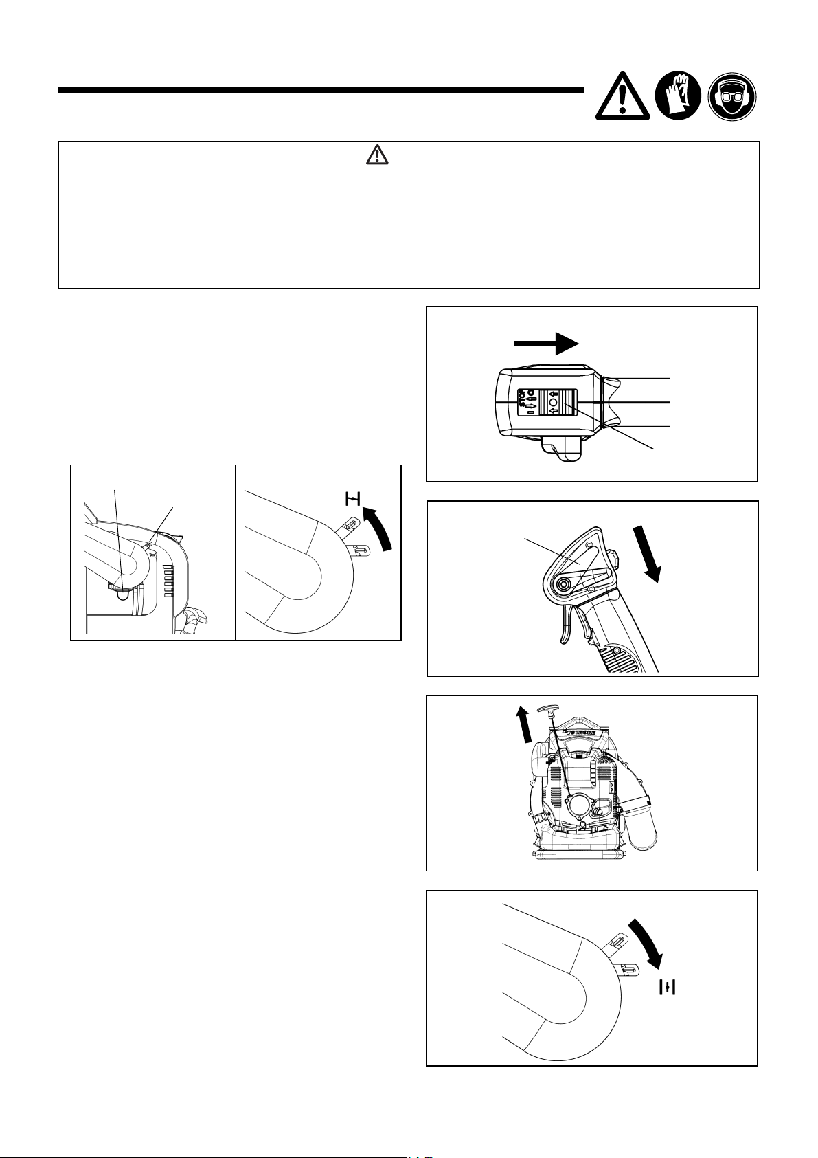
1) When the engine is cold or after refuelling
(1) Set this machine on a flat space.
(2) Set the stop switch to “ I ” position.
(3) Make sure that the cruise control lever is in the low-speed
position.
(4) Continue to push the primer pump until fuel comes into the
primer pump.
• In general, fuel comes into the carburetor by 7 to 10 pushes.
• If the primer pump is pushed excessively, an excess of
gasoline returns to the fuel tank.
(5) Lift the choke lever to the closed position.
(6) Hold the element cover with left hand to prevent the engine
from moving.
(7) Pull out slowly the starter handle till a certain resistance is felt.
Return the starter handle backward once from this position,
then pull it out with force.
• Never pull the rope to the full extension.
• Once the start knob is pulled, never release your hand
immediately. Hold the start knob until it returns to its original
point.
(8) When the engine starts, open the choke lever.
• Open the choke lever fully when checking the engine operation.
• In cold or when the engine is cooled down, never open the
choke lever suddenly. Otherwise, the engine may stop.
(9) Continue warm-up operation for 2 to 3 minutes.
(10) Warm-up is complete when there is quick engine acceleration
from low rpm to full throttle.
12
Page 13
NOTE
Cruise control lever
Hi-speed
Low-speed
Stop Switch
Carburetor
Adjusting screw
• The engine may be damaged if the choke lever is moved further beyond the “CLOSE” position.
• If the engine fires and stops, return this lever to the “OPEN” position and pull the starter handle several times to start the engine again.
• If the operator keeps pulling the starter handle several times with the choke lever left in the “CLOSE” position, the engine may be difficult to
start because of flooding of the fuel.
• In case of flooding of the fuel, remove the spark plug and pull the handle several times rapidly to discharge any excess fuel. Dry the spark
plug electrode.
• When the throttle valve does not return to a position in contact with the idling adjusting screw even if the throttle lever is set to the low speed,
correct the control cable catching state to ensure proper return of the valve.
2) When the engine is warm
(1) Put the engine on a flat ground.
(2) Press the primary pump several times.
(3) Make sure that the choke lever is open.
(4) Hold the element cover with left hand to prevent the engine from moving.
(5) Pull out slowly the starter handle till a certain resistance is felt. Return the starter handle backward once from this position, then pull it
out with force.
(6) When the engine is difficult to start, open the throttle valve by about 1/3.
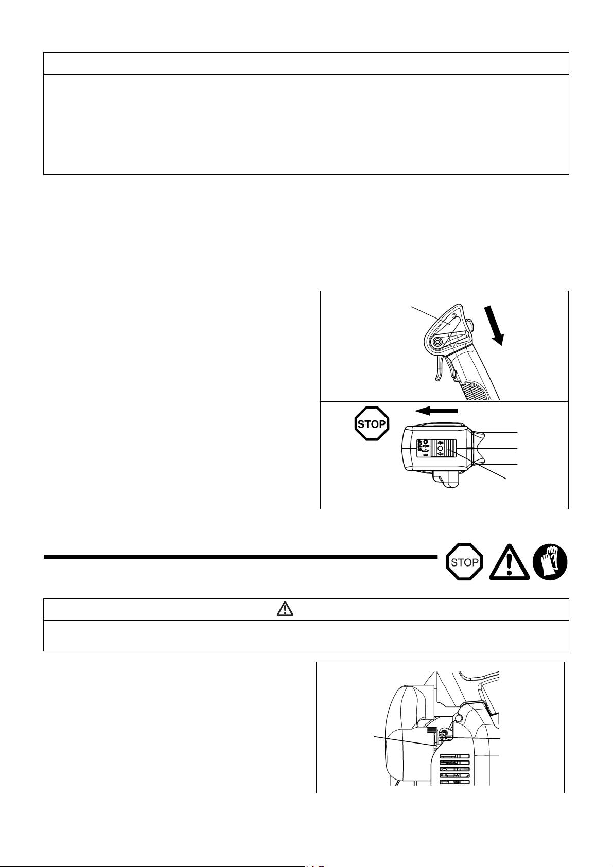
2. Stopping
1) When the cruise control lever is a Low-speed position.
Release the trigger lever to reduce the engine speed, and set the
stop switch to the “O” position.
2) When the cruise control lever is except a Low-speed
position.
Set the cruise control lever to the Low-speed position, reduce the
engine speed, and set the stop switch to the “O” position.
ADJUSTMENT OF IDLING
The carburetor is factory adjusted. Please do not adjust other than idling adjusting. When adjustment becomes necessary, please consult your
dealership or an authorized service agent.
Checkup of low-speed rotation
Set the low-speed rotation to 2800 rpm (/min).
• If it is necessary to change the rotation speed, regulate the adjusting
screw, with Phillips screwdriver.
• Turn the adjusting screw to the right, and the engine speed will
increase. Turn the adjusting screw to the left, and the engine speed will
drop.
DANGER
13
Page 14
OPERATION METHOD
To tighten straps To loosen straps
Cruise control lever
Hi-speed
Low-speed
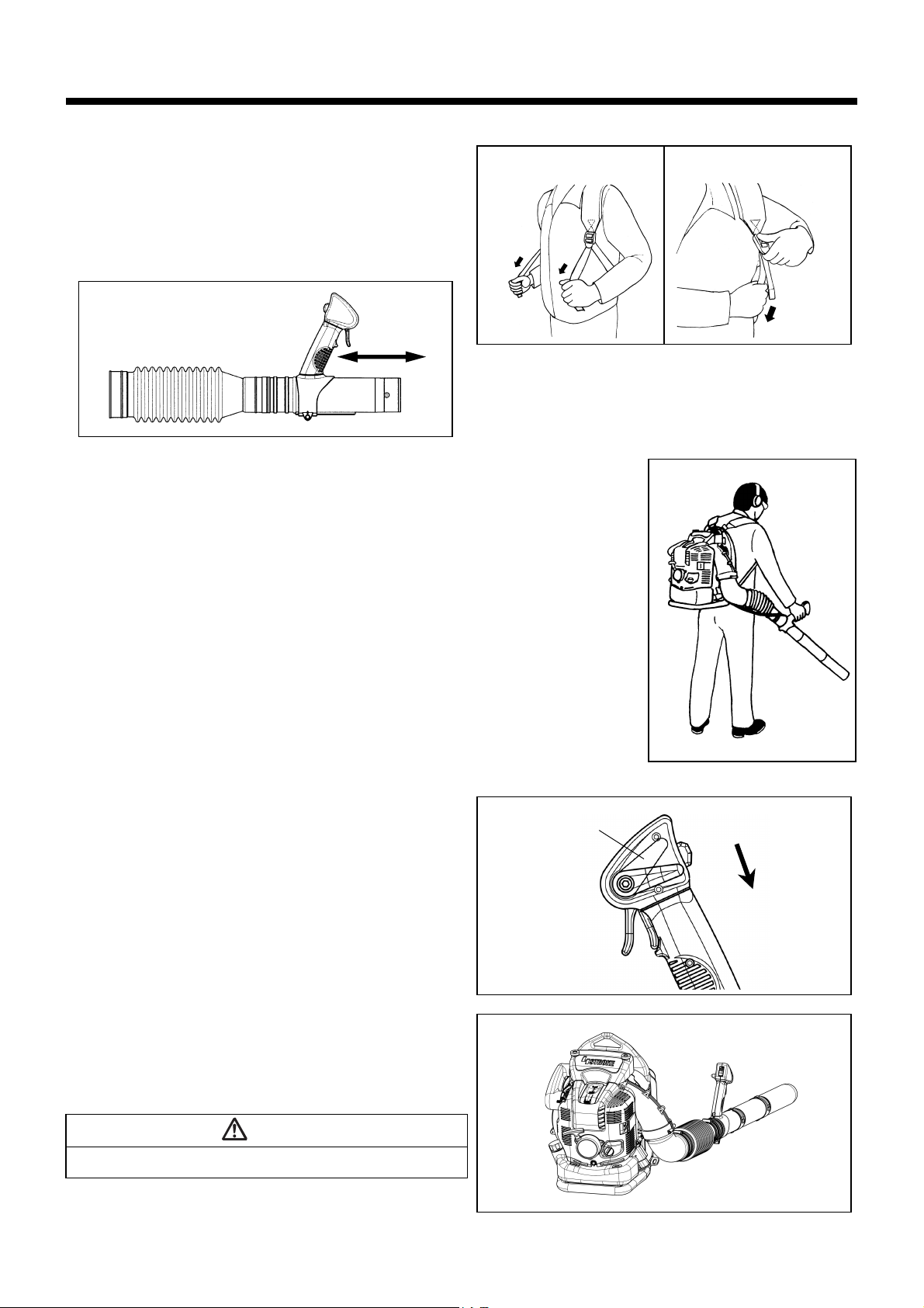
1. Adjusting Shoulder strap
Adjust the shoulder strap to a length that is comfortable to work while
carrying the blower.
Adjust as shown in the figure.
2. Adjusting the control lever
Move the control handle along the swivel pipe to the most comfortable
position.
3. Blower Operation
While operating the blower, adjust the throttle bar so that the wind force
is appropriate for the work location and conditions.
Low speed: Dried leaves and grass
High speed: Gravel and dirt
The cruise control lever allows the operator to maintain a constant
engine speed without operating the trigger lever.
Lifting the cruise control lever increases engine speed.
Lowering the cruise control lever decreases engine speed.
Adjusting engine speed when the cruise control lever is being used:
When increasing engine speed:
• Pull the trigger lever to increase engine speed. Engine speed returns
to its original setting when the trigger lever is released.
• Increasing the engine speed in this manner also increases the cruise
control setting. The cruise control lever lifts simultaneously as the
trigger lever is pulled, and the new cruise control setting will be maintained at the higher engine speed.
When reducing engine speed:
• Lower the cruise control lever to the low-speed position.
TRANSPORTING AND STORING THE BLOWER
Please maintain the blower in an upright position whenever transporting
or storing. (Refer to Figure at right.)
Transporting or storing in a position that is not upright may cause oil to
spill inside the blower engine. This may result in oil leaks and white
smoke from burning oil, and the air cleaner may become dirty with oil.
DANGER
• When transporting the blower, be sure to stop the engine.
14
Page 15
INSPECTION AND MAINTENANCE
(1)
(2)
(3)
(4)
DANGER
• Before inspection and maintenance, stop the engine and allow it to cool down. Remove the spark plug and plug cap.
- Otherwise the operator may suffer burn or serious injury due to an accidental start-up.
• After inspection and maintenance, make sure that all parts are assembled. Then, proceed to operation.
1. Replacement of engine oil
Deteriorated engine oil will shorten the life of the sliding and rotating parts to a great extent. Be sure to check the period and quantity of replacement.
DANGER
• In general, the engine main unit and engine oil still remain hot just after the engine is stopped. In replacement of oil, make sure that the
engine main unit and engine oil are sufficiently cooled down. Otherwise, there may remain a risk of scald. Allow sufficient time after stopping
engine for the engine oil to return to the oil tank to ensure accurate reading of the oil level indicator.
• If the oil filled above the limit, it may become dirty or may catch fire with white smoke.
Interval of replacement: After first 20 operating hours, followed by every 50 operating hours
Recommended oil: SAE10W-30 oil of API Classification SF Class or higher (4-stroke engine oil for automobile)
Oil Change Procedure
Please follow these steps when changing the oil:
(1) Set the blower down on a level surface.
(2) Put a waste oil container under the drainage hole (1) to catch the oil as it
drains out. The container should have a capacity of at least 220 ml to be
able to catch all of the oil.
(3) Loosen the oil drain bolt (2) to let the oil drain out. Be careful not to allow oil
to get on the fuel tank or other parts.
Caution: Be careful not to lose the gasket (aluminum washer) (3). Put the
oil drain bolt (2) in a location where it will not accumulate dirt.
(4) Remove the oil cap (4). (Removing the oil cap (4) allows the oil to drain
easily.)
Caution: Be sure to set the oil cap (4) down in a location where it will not
(5) As the level of the oil being drained decreases, tilt the blower over on to the
side with the drain so that the oil will completely drain out.
(6) After the oil has completely drained out, tighten the oil drain bolt (2)
securely. If the bolt is not tightly fastened, this may result in an oil leak.
Caution: Do not forget to put the gasket (aluminum washer) (3) back on
(7) Adding oil during the oil change procedure is performed in the same man-
ner as the separately explained procedure for adding oil whenever the
level is insufficient. Always add oil by filling from the opening under the oil
cap.
(Specified oil level: Approximately 220 ml)
(8) After filling with oil, tighten the oil cap (4) securely to prevent oil leaks.
accumulate dirt.
when reattaching the drain plug.
Points in replacement of engine oil
• Never discard replaced engine oil in garbage, earth or sewage ditch. Disposal of oil is regulated by law. In disposal, always follow the relevant
laws and regulations. For any points remaining unknown, contact Authorized Service Agent.
• Oil will deteriorate even when it is kept unused. Perform inspection and replacement at regular intervals (replace with new oil every 6 months).
15
Page 16
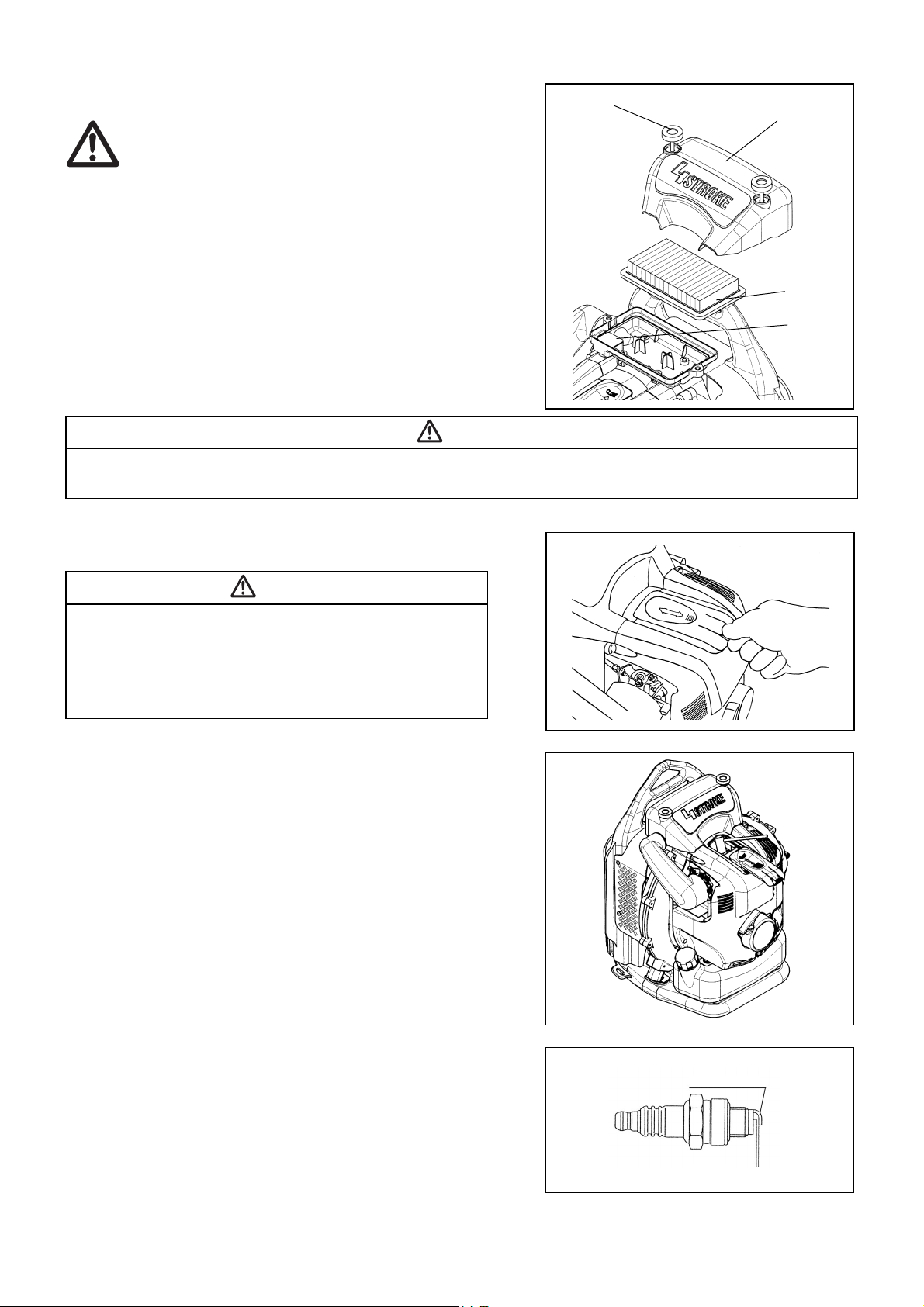
2. Cleaning of air cleaner
Element
Breather
Element cover
Knob bolt
Electrode clearance
0.7 - 0.8 mm
Lateral electrode (–)
WARNING: INFLAMMABLES STRICTLY PROHIBITED
Interval of Cleaning and Inspection: Daily (every 10 operating hours)
(1) Loosen the knob bolts.
(2) Remove the air cleaner cover.
(3) Take out the element and remove any dirt from the element with the brush.
Note: The element is a dry type and should not get wet. Never wash with
water.
(4) Replace the element with a new one if it is damaged or very dirty.
(5) Wipe off any oil that has come in to contact with the breather with a rag or
cloth.
(6) Install the element in the cleaner case.
(7) Attach the air cleaner cover and tighten the knob bolt.
DANGER
• Clean the element several times a day, if excessive dust adheres to it.
• If operation continues with the element remaining not cleared of oil, oil in the air cleaner may fall outside, resulting in oil contamination.
3. Checking the spark plug
CAUTION
• When removing the spark plug, clean the spark plug and cylinder head
first, so that no dirt, sand, etc will enter the cylinder.
• You must remove the spark plug after the engine has cooled down in
order to avoid damaging the threaded hole in the cylinder.
• The spark plug must be installed properly into the threaded hole. If
installed at an angle, the threaded hole in the cylinder will get damaged.
(1) Opening/closing the plug cover
To open the plug cover, pull up on the seam of the plug cover projection
and slide in the direction of the “OPEN” indication as shown in the figure at
right.
When closing the cover, slide the cover in the “CLOSE” direction till the
click under the plug cover projection rides over the engine cover. Finally,
push in the projection.
(2) Removing the spark plug
Use an attached box wrench to remove or install the spark plug.
(3) Checking the spark plug
The clearance between two electrodes of spark plug (see the figure left) is
0.7 to 0.8 mm. Adjust to the correct clearance when it is too wide or too
narrow.
Clean thoroughly or replace the spark plug if it has accumulated carbon or
contaminated.
(4) Replacing the spark plug
For replacement, use NGK-CMR6A.
16
Page 17
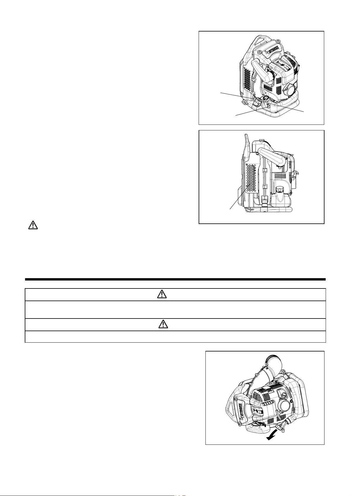
4. Cleaning the fuel filter
Hose clamp
Fuel filter
Fuel tank cap
Air inlet net
• Clogged fuel filter may cause difficulty of start-up or failure of engine speed
increase.
• Check the fuel filter regularly as follows:
(1) Remove the fuel tank cap, drain the fuel to empty the tank. Check the
tank inside for any foreign materials. If any, wipe clean such materials.
(2) Pull out the fuel filter with wire through the oil filling port.
(3) If the fuel filter surface is contaminated, clean it with gasoline. The gaso-
line used for the cleaning must be disposed of according to the method
specified by each local authority. Excessively contaminated filter must be
replaced.
(4) Reset the fuel filter in the fuel tank and tighten firmly the fuel tank cap. For
replacement, contact your dealership or an authorized service agent.
5. Inspection of bolts, nuts and screws
• Retighten loose bolts, nuts, etc.
• Check for fuel and oil leakage.
• Replace damaged parts with new ones for safety operation.
6. Cleaning of parts
• Keep engine clean by wiping down with a cloth rag.
• Keep the cylinder fins free of dust or dirt. Dust or dirt adhering to the fins will
cause seizure.
• Blowing air is taken in from the air inlet net. When airflow has dropped down
during operation, stop engine and inspect the air inlet net for blocking by
obstacles.
• Such a blockage may cause overheat and damage the engine.
WARNING:
Never use the blower without the net of the blower. Before each use,
check that the net is attached in place and is free from any damage.
7. Replacement of gaskets and packings
Replace gaskets and packings if the engine is disassembled.
Any maintenance of adjustment work that is not included and described in this manual is only to be performed by Authorized Service Agent.
STORAGE
WARNING
• When draining the fuel, stop the engine and wait for the engine to cool down.
- Failure to do so may cause burns or fire.
DANGER
• When you store the machine for a long time, drain all fuel from the fuel tank and carburetor, and keep it at a dry and clean place.
Drain fuel from the fuel tank and carburetor according to the following
procedure:
(1) Remove the fuel tank cap, and drain fuel completely.
If there is any foreign materials remaining in the fuel tank, remove it
completely.
(2) Pull out the fuel filter from the refill port using a wire.
(3) Push the primer pump until fuel is drained from there, and drain fuel
coming into the fuel tank.
(4) Reset the filter to the fuel tank, and securely tighten the fuel tank cap.
(5) Then, continue to operate the engine until it stops.
(6) Remove the spark plug, and drip several drops of engine oil through the
spark plug hole.
(7) Gently pull the starter handle so that engine oil will spread over the engine,
and attach the spark plug.
(8) Keep the machine with its handle upside.
(9) Keep the drained fuel in a special container in a well-ventilated shade.
17
Page 18
Fault location
Fault System Observation Cause
Engine not starting or
with difficulty
Warm start problems Tank filled ignition spark
Engine starts but dies Fuel supply Tank filled Incorrect idling adjustment, carburetor contaminated
Insufficient performance Several systems may
Ignition system Ignition spark O.K. Fault in fuel supply or compression system, mechanical
defect
No ignition spark STOP-switch operated, wiring fault or short circuit, spark plug
or connector defective, ignition module faulty
Fuel supply Fuel tank filled Incorrect choke position, carburetor defective, fuel supply
line bent or blocked, fuel dirty.
Compression No compression when
pulled over
Cylinder bottom gasket defective, crankshaft seals damaged,
cylinder or piston rings defective or improper sealing of spark
plug
Mechanical fault Starter not engaging Broken starter spring, broken parts inside of the engine
Carburetor contaminated, have it cleaned
existing
Fuel tank vent defective, fuel supply line interrupted, cable or
STOP-switch faulty
Engine idling poor Air filter contaminated, carburetor contaminated, muffler
simultaneously be
clogged, exhaust duct in the cylinder clogged
affected
3
3
Corre-
sponding
Page
15
17
17
Operating time
Item
Engine oil
Tightening parts (bolt, nut) Inspect 17
Fuel tank
Throttle lever Check function –
Stop switch Check function 12
Low-speed rotation Inspect/adjust 13
Air cleaner Clean 16
Ignition plug Inspect 16
Cooling air duct Clean/inspect 17
Fuel pipe
Fuel filter Clean/replace 17
Clearance between air intake
valve and air discharge valve
Oil tube Inspect *
Engine overhaul *
Carburetor Drain fuel *
Inspect/clean 10
Replace *
Clean/inspect –
Drain fuel *
Inspect 17
Replace *
Adjust *
Before
operation
After
lubrication
Daily (10h) 30h 50h 200h
1
Shutdown/
rest
2
2
2
2
–
–
–
–
*1 Perform initial replacement after 20h operation.
*2 For the 200 operating hour inspection, request Authorized Service Agent or a machine shop.
*3 After emptying the fuel tank, continue to run the engine and drain fuel in the carburetor.
18
Page 19

TROUBLESHOOTING
Run engine at idling, and set choke lever to
CLOSE.
Before making a request for repairs, check a trouble for yourself. If any abnormality is found, control your machine according to the description of
this manual. Never tamper or dismount any part contrary to the description. For repairs, contact Authorized Service Agent or local dealership.
State of abnormality Probable cause (malfunction) Remedy
Failure to operate primer pump Push 7 to 10 times.
Low pulling speed of starter rope Pull strongly.
Lack of fuel Feed fuel.
Clogged fuel filter Clean
Broken fuel tube Straighten fuel tube
Deteriorated fuel Deteriorated fuel makes starting more difficult.
Replace with new one. (Recommended
replacement: 1 month)
Engine does not start
Engine stops soon
Engine speed does not increase
Excessive suction of fuel Set throttle lever from medium speed to high
Detached plug cap Attach securely
Contaminated spark plug Clean
Abnormal clearance of spark plug Adjust clearance
Other abnormality of spark plug Replace
Abnormal carburetor Make request for inspection and maintenance.
Starter rope cannot be pulled Make request for inspection and maintenance.
Abnormal drive system Make request for inspection and maintenance.
Insufficient warm-up Perform warm-up operation
Choke lever is set to “CLOSE” although
engine is warmed up
Clogged fuel filter Clean
Contaminated or clogged air cleaner Clean
Abnormal carburetor Make request for inspection and maintenance.
Abnormal drive system Make request for inspection and maintenance.
Detached throttle wire Attach securely
speed, and pull starter handle until engine
starts.
If engine will not start still, remove spark plug,
make electrode dry, and reassemble them as
they originally are. Then, start as specified.
Set to “OPEN”
Engine does not stop. Detached connector Attach securely
Abnormal electric system Make request for inspection and maintenance.
When the engine does not start after warm-up operation:
If there is no abnormality found for the check items, open the throttle by about 1/3 and start the engine.
19
Page 20

Makita LIMITED ONE YEAR WARRANTY
Warranty Policy
Every Makita tool is thoroughly inspected and tested before leaving the factory. It is warranted to be free of defects from
workmanship and materials for the period of ONE YEAR from the date of original purchase. Should any trouble develop during
this one year period, return the COMPLETE tool, freight prepaid, to one of Makita’s Factory or Authorized Service Centers. If
inspection shows the trouble is caused by defective workmanship or material, Makita will repair (or at our option, replace) without
charge.
This Warranty does not apply where:
repairs have been made or attempted by others:
repairs are required because of normal wear and tear:
the tool has been abused, misused or improperly maintained:
alterations have been made to the tool.
IN NO EVENT SHALL Makita BE LIABLE FOR ANY INDIRECT, INCIDENTAL OR CONSEQUENTIAL DAMAGES FROM THE
SALE OR USE OF THE PRODUCT. THIS DISCLAIMER APPLIES BOTH DURING AND AFTER THE TERM OF THIS
WARRANTY.
Makita DISCLAIMS LIABILITY FOR ANY IMPLIED WARRANTIES, INCLUDING IMPLIED WARRANTIES OF
“MERCHANTABILITY” AND “FITNESS FOR A SPECIFIC PURPOSE,” AFTER THE ONE YEAR TERM OF THIS WARRANTY.
This Warranty gives you specific legal rights, and you may also have other rights which vary from state to state.
Some states do not allow the exclusion or limitation of incidental or consequential damages, so the above limitation or exclusion
may not apply to you. Some states do not allow limitation on how long an implied warranty lasts, so the above limitation may not
apply to you.
20
Page 21
EMISSION COMPLIANCE PERIOD
Descriptive term Applicable to Emissions Durability Period
Moderate 50 hours (0-80 cc, inclusive)
Intermediate 125 hours (0-80 cc, inclusive)
Extended 300 hours (0-80 cc, inclusive)
For handheld engines : The Emissions Compliance Period referred to on the
Emissions Compliance label indicates the number of operating hours for which
the engine has been shown to meet Federal emission requirements.
Category C=50 hours, B=125 hours, and A=300 hours.
Air Index and durability period information
The Air Index Information hang-tag for this engine is provided in accordance
with the California emission regulations.
The graphical representation of the Air Index on the hang-tag shows the
emissions performance of this engine, and can be used to compare the
emissions performance with other available engines.
The lower the Air Index, the less pollution.
Note: Remove the hang-tag before operating the engine.
The Emissions Durability Period referred to on the hang-tag indicates the
number of operating hours for which the engine has been shown to meet the
California emission requirements.
21
Page 22

FEDERAL EMISSION COMPONENT DEFECT WARRANTY
EMISSION COMPONENT DEFECT WARRANTY COVERAGE - This emission warranty is applicable in all States,
except the State of California
Makita U.S.A., Inc., (herein “Makita”) warrant to the initial retail purchaser and each subsequent owner, that this
utility equipment engine (herein “engine”) was designed, built, and equipped to conform at the time of initial sale to
all applicable regulations of the U.S. Environmental Protection Agency (EPA), and that the engine is free of defects
in materials and workmanship which would cause this engine to fall to conform with EPA regulations during its
warranty period.
For the components listed under PARTS COVERED, the dealer or service center authorized by Makita will, at no
cost to you, make the necessary diagnosis, repair, or replacement necessary to ensure that the engine complies
with applicable U.S. EPA regulations.
EMISSION COMPONENT DEFECT WARRANTY PERIOD
The warranty period for this engine begins on the date of sale to the initial purchaser and continues for a period of
2 years.
PARTS COVERED
Listed below are the parts covered by the Emission Component Defect Warranty. Some of the parts listed below may
require scheduled maintenance and are warranted up to the first scheduled replacement point for that part.
1) Fuel Metering System 4) Miscellaneous Items Used in Above Systems
(i) Carburetor and internal parts
(i) Fuel hoses, clamps and sealing gaskets
(ii) Fuel filter, if applicable
(iii) Throttle stopper, if applicable
(iv) Choke System, if applicable
2) Air Induction System 5) Emission-related components for evaporative emission
(i) Air cleaner plate
(ii) Air cleaner case
(iii) Air cleaner element
(i) Fuel Tank
(ii) Fuel Cap
(iii) Fuel line
(iv) Fuel line fitting
(v) Clamps
3) Ignition System
(i) Spark plug
(ii) Flywheel Magneto
(iii) Ignition Coil
22
Page 23

OBTAINING WARRANTY SERVICE
To obtain warranty service, take your engine to the nearest Makita Factory Service Center authorized by Makita.
Bring your sales receipts indicating date of purchase for this engine. The dealer or service center authorized by
Makita will perform the necessary repairs or adjustments within a reasonable amount of time and furnish you with a
copy of the repair order. All parts and accessories replaced under this warranty become the property of Makita.
WHAT IS NOT COVERED
* Conditions resulting from tampering, misuse, improper adjustment (unless they were made by the dealer or
service center authorized by Makita during a warranty repair), alteration, accident, failure to use the recommended
fuel and oil, or not performing required maintenance services.
* The replacement parts used for required maintenance services.
* Consequential damages such as loss of time, inconvenience, loss of use of the engine of equipment, etc.
* Diagnosis and inspection charges that do not result in warranty-eligible service being performed.
* Any non-authorized replacement part, or malfunction of authorized parts due to use of non-authorized parts.
OWNER’S WARRANTY RESPONSIBILITIES
As the engine owner, you are responsible for the performance of the required maintenance listed in your owner’s
manual, Makita recommends that you retain all receipts covering maintenance on your engine, but Makita can not
deny warranty solely for the lack of receipts or for your failure to ensure the performance of all scheduled
maintenance.
As the engine owner, you should however be aware that the Makita may deny your warranty coverage if your engine
or a part has failed due to abuse, neglect, improper maintenance or unapproved modifications.
You are responsible for presenting your engine to the nearest dealer or service center authorized by Makita when a
problem exists.
If you have any questions regarding your warranty rights and responsibilities, you should contact the Followings:
* For the nearest Makita service center, please visit www.makitatools.com
* For technical support or questions regarding operation of our tools and accessories call: 1-800-4-Makita
* Makita USA Inc. Corporate Office: 14930 Northam St. La Mirada, CA 90638-5753
(For Canada)
* For the authorized service center nearest you please refer to the local yellow pages directory under “tools”, or
contact our customer service department Tel 1-800-263-3734(Canada only), or visit our web site www.makita.ca
* Makita Canada Inc. Head Office & Plant: 1950 Forbes Street, Whitby, ON L1N7B7.
23
Page 24

THINGS YOU SHOULD KNOW ABOUT THE EMISSION CONTROL SYSTEM WARRANTY
MAINTENANCE AND REPAIRS
You are responsible for the proper use and maintenance of the engine. You should keep all receipts and
maintenance records covering the performance of regular maintenance in the event questions arise. These receipts
and maintenance records should be transferred to each subsequent owner of the engine. Makita reserves the rights
to deny warranty coverage if the engine has not been properly maintained. Warranty claims will not be denied,
however, solely because of the lack of required maintenance or failure to keep maintenance records.
MAINTENANCE, REPLACEMENT OR REPAIR OF EMISSION CONTROL DEVICES AND
SYSTEMS MAY BE PERFORMED BY ANY REPAIR ESTABLISHMENT OR INDIVIDUAL;
HOWEVER, WARRANTY REPAIRS MUST BE PERFORMED BY A DEALER OR SERVICE
CENTER AUTHORIZED BY Makita. THE USE OF PARTS THAT ARE NOT EQUIVALENT IN
PERFORMANCE AND DURABILITY TO AUTHORIZED PARTS MAY IMPAIR THE
EFFECTIVENESS OF THE EMISSION CONTROL SYSTEM AND MAY HAVE A BEARING ON
THE OUTCOME OF A WARRANTY CLAIM.
If other than the parts authorized by Makita are used for maintenance replacements or for the repair of components
affecting emission control, you should assure yourself that such parts are warranted by their manufacturer to be
equivalent to the parts authorized by Makita in their performance and durability.
HOW TO MAKE A CLAIM
All repairs qualifying under this limited warranty must be performed by a service dealer authorized by Makita. In
the event that any emission-related part is found to be defective during the warranty period, you shall notify Makita
at the following contacts and you will be advised of the appropriate warranty service dealer or service
providers where the warranty repair can be performed.
* For the nearest Makita service center, please visit www.makitatools.com
* For technical support or questions regarding operation of our tools and accessories call: 1-800-4-Makita
* Makita USA Inc. Corporate Office: 14930 Northam St. La Mirada, CA 90638-5753
(For Canada)
* For the authorized service center nearest you please refer to the local yellow pages directory under “tools”, or
contact our customer service department Tel 1-800-263-3734(Canada only), or visit our web site www.makita.ca
* Makita Canada Inc. Head Office & Plant: 1950 Forbes Street, Whitby, ON L1N7B7.
24
Page 25

CALIFORNIA EMISSIONS CONTROL WARRANTY STATEMENT
YOUR WARRANTY RIGHTS AND OBLIGATIONS
The California Air Resources Board and Makita USA, Inc are pleased to explain the emissions control system’s
warranty on your 2007 and later small off-road engine. In California, new equipment that use small off-engines must
be designed, built, and equipped to meet the State’s stringent anti-smog standards. Makita USA, Inc must warrant
the emissions control system on your small off-road engine for the period listed below provided there has been no
abuse, neglect or improper maintenance of your equipment.
Your emissions control system may include parts such as: carburetors or fuel injection system, ignition system,
catalytic converters, fuel tanks, valves, filters, clamps, connectors, and other associated components. Also, included
may be hoses, belts, connectors, sensors, and other emission-related assemblies.
Where a warrantable condition exists, Makita USA, Inc will repair your small off-road engine at no cost to you
including diagnosis, parts and labor.
MANUFACTURER’S WARRANTY COVERAGE:
This emissions control system is warranted for two years. If any emissions-related part on your equipment is
defective, the part will be repaired or replaced by Makita USA, Inc.
OWNER’S WARRANTY RESPONSIBILITIES:
• As the small off-road engine owner, you are responsible for performance of the required maintenance listed in your
owner’s manual. Makita USA, Inc recommends that you retain all receipts covering maintenance on your small
off-road engine, but Makita USA, Inc cannot deny warranty solely for the lack of receipts or your failure to ensure
the performance of all scheduled maintenance.
• As the small off-road engine owner, you should however be aware that Makita USA, Inc may deny you warranty
coverage if your small off-road engine or a part has failed due to abuse, neglect, or improper maintenance or
unapproved modifications.
• You are responsible for presenting your small off-road engine to a Makita Factory Service Center as soon as the
problem exists. The warranty repairs should be completed in a reasonable amount of time, not to exceed 30 days.
If you have a question regarding your warranty coverage, you should contact:
* For the nearest Makita service center, please visit www.makitatools.com
* For technical support or questions regarding operation of our tools and accessories call: 1-800-4-Makita
* Makita USA Inc. Corporate Office: 14930 Northam St. La Mirada, CA 90638-5753
DEFECTS WARRANTY REQUIREMENTS:
(a) The warranty period begins on the date the engine or equipment is delivered to an ultimate purchaser.
(b) General Emissions Warranty Coverage. Makita USA, Inc must warrant to the ultimate purchaser and each
subsequent owner that the engine or equipment is:
(1) Designed, built, and equipped so as to conform with all applicable regulations adopted by the Air
Resources Board; and
(2) Free from defects in materials and workmanship that causes the failure of a warranted part for a period of
two years.
(c) The warranty on emissions-related parts will be interpreted as follows:
25
Page 26

(1) Any warranted part that is not scheduled for replacement as required maintenance in the written
instructions required by subsection (d) must be warranted for the warranty period defined in Subsection
(b)(2). If any such part fails during the period of warranty coverage, it must be repaired or replaced by the
manufacturer according to Subsection (4) below. Any such part repaired or replaced under the warranty
must be warranted for the remaining warranty period.
(2) Any warranted part that is scheduled only for regular inspection in the written instructions required by
subsection (d) must be warranted for the warranty period defined in Subsection (b)(2). A statement in such
written instructions to the effect of “repair or replace as necessary” will not reduce the period of warranty
coverage. Any such part repaired or replaced under warranty must be warranted for the remaining warranty
period.
(3) Any warranted part that is scheduled for replacement as required maintenance in the written instructions
required by subsection (d) must be warranted for the period of time prior to the first scheduled replacement
point for that part. If the part fails prior to the first scheduled replacement, the part must be repaired or
replaced by the engine manufacturer according to Subsection (4) below. Any such part repaired or replaced
under warranty must be warranted for the remainder of the period prior to the first scheduled replacement
point for the part.
(4) Repair or replacement of any warranted part under the warranty must be performed at no charge to the
owner at a warranty station.
(5) Notwithstanding the provisions of Subsection (4) above, warranty services or repairs must be provided at
all manufacturer distribution centers that are franchised to service the subject engines.
(6) The owner must not be charged for diagnostic labor that leads to the determination that a warranted part is
in fact defective, provided that such diagnostic work is performed at a warranty station.
(7) The manufacturer is liable for damages to other engine components proximately caused by a failure under
warranty of any warranted part.
(8) Throughout the emissions warranty period defined in Subsection (b)(2), the manufacturer must maintain a
supply of warranted parts sufficient to meet the expected demand for such parts.
(9) Any replacement part may be used in the performance of any warranty maintenance or repairs and must be
provided without charge to the owner. Such use will not reduce the warranty obligations of the
manufacturer.
(10) Add-on or modified parts that are not exempted by the Air Resources Board may not be used. The use of
any non-exempted add-on or modified parts will be grounds for disallowing a warranty claim. The
manufacturer will not be liable to warrant failures of warranted parts caused by the use of a non-exempted
add-on or modified part.
(11) The manufacturer issuing the warranty shall provide any documents that describe that manufacturer’s
warranty procedures or policies within five working days of request by the Air Resources Board.
(d) Emission Warranty Parts List.
(1) Fuel Metering System
(i) Carburetor and internal parts
(ii) Fuel Filter
(iii) Fuel Tank.
(2) Air Induction System
(i) Air cleaner plate (including choke system)
(ii) Air cleaner cover
(iii) Air cleaner element
26
Page 27

(3) Ignition System
(i) Spark Plugs.
(ii) Magneto or electronic ignition system.
(iii) Spark advance/retard system.
(4) Miscellaneous Items Used in Above Systems
(i) Hoses, Sealing gaskets, belts, connectors, and assemblies.
Makita USA, Inc will furnish with each new engine written instructions for the maintenance and use of the engine by
the owner.
(e) MAINTENANCE STATEMENTS
It is your responsibility to have all scheduled inspection and maintenance services performed at the times
recommended in the 2007 and later Owner’s Manual and to retain proof that inspection and maintenance services
are performed at the times when recommended. Makita USA, Inc will not deny a warranty claim solely because you
have no record of maintenance;
however, Makita USA, Inc may deny a warranty claim if your failure to perform required maintenance resulted in the
failure of warranted part. The proof, which you maintain, should be given to each subsequent owner of the engine.
You are responsible for performing the scheduled maintenance described below based on the procedures specified
in the 2007 and later Owner’s Manual. The scheduled maintenance below is based on the normal engine-operating
schedule.
PROCEDURE INTERVAL
1) Clean engine and check bolts and nuts.
:Every 8 hours(daily)
Retighten if necessary.
2) Check and refill engine oil (4stroke engine
:Every 8 hours(refill daily up to upper limit)
only)
3) Change engine oil (4stroke engine only) :Initial 20 hours and every 50 hours afterward
4) Check clogging of cooling air passage and
:Every 8 hours (daily)
cylinder fins. Remove and clean if necessary.
5) Clean air cleaner. :Every 8 hours (daily)
6) Check spark plug. Clean and adjust if
:Every 8 hours (daily)
necessary.
7) Check muffler exhaust outlet(or port).
:Every 50 hours (monthly)
Clean if necessary.
8) Check fuel filter. If clogged, replace with new
:Every 50 hours (monthly)
one.
9) Adjust valve clearance, if applicable (4stroke
:Every 200 hours (yearly)
engine only).
10) Replace fuel lines. :Every 200 hours (yearly)
11) Clean and inspect the complete engine.
:Every 200 hours
Replace any damaged or worn out parts.
12) Replace packings and gaskets with new
:Every reassembling
ones.
27
Page 28

Français
Vous venez d’acheter un souffleur Makita, fruit d’importants
programmes de développement et de nombreuses années d’études et
d’expérience et nous vous en remercions.
Les modèles BBX7600 / BBX7600CA légers, pratiques et compacts,
allient les avantages d’une technologie de pointe à une conception
ergonomique et sont des outils de professionnels pour de nombreuses
applications.
Lisez soigneusement le manuel, qui traite en détail des différents
points des performances de la machine et vous aidera à en tirer le
meilleur parti possible.
Table des Matières
Symboles ........................................................................................... 28
Consignes de sécurité .................................................................. 29-30
Caractéristiques techniques............................................................... 32
Liste des pièces ................................................................................. 33
Instructions de montage................................................................ 34-35
Avant de démarrer le moteur ........................................................36-37
Fonctionnement ............................................................................38-39
Réglage du ralenti.............................................................................. 39
Mode opératoire................................................................................. 40
Inspection et maintenance ............................................................41-43
Remisage...................................................................................... 43-44
Dépannage ........................................................................................ 45
SYMBOLES
Lors de la lecture de ce manuel, prêtez une attention particulière aux symboles ci-après :
Page
Attention! Danger! Essence et huile
Lire et suivre le manuel de fonctionnement Moteur - Mise en marche manuelle
Interdit Arrêt d’urgence
Interdiction de fumer Premiers secours
Interdiction d’utilisation de produits
inflammables
Port de gants de protection obligatoire Marche
Zone de fonctionnement interdite aux
humains et aux animaux
Recyclage
Arrêt
Port de lunettes de protection et cacheoreilles obligatoire
Surfaces chaudes - Risque de brûlures
Mutilation du doigt ou du bras, Roue mobile
28
Page 29

CONSIGNES DE SECURITE
(1)
(2)
(3)
(4)
(5)
15 mètres
Généralités
• Pour tirer le meilleur parti de votre machine, vous devez lire, assimiler
et respecter les instructions figurant dans ce manuel (1). Les
utilisateurs mal informés risquent, par des manipulations
inappropriées, de se blesser ou de blesser leur entourage.
• Il est conseillé de ne prêter cet appareil qu’aux personnes ayant déjà
une certaine expérience des souffleurs.
• Dans ce cas, leur confier aussi le manuel d’instruction.
• Les utilisateurs qui ne connaissent pas encore le fonctionnement de la
machine devront demander à leur vendeur les explications qui leur
permettront de se familiariser avec le souffleur.
• Les enfants et les adolescents ne doivent pas être autorisés à utiliser
la machine. Au-delà de 16 ans, ils peuvent cependant apprendre à
s’en servir, mais uniquement sous le contrôle direct d’une personne
qualifiée.
• Soyez toujours très prudent.
• N’utilisez la machine que si vous êtes en bonne condition physique.
• Faites très attention à tout ce que vous faites. N’oubliez pas que vous
êtes responsable des autres.
• N’utilisez jamais l’appareil lorsque vous avez bu ou pris des calmants
(2).
• N’utilisez pas l’appareil lorsque vous êtes fatigué.
• Conservez soigneusement ce manuel afin de pouvoir vous y référer
ultérieurement.
Equipements de protection
• Portez des vêtements fonctionnels, c’est-à-dire des vêtements légers,
ne provoquant aucune gêne. Evitez les bijoux, les vêtements ou les
cheveux longs, qui pourraient être happés par l’entrée d’air.
• Pour éviter de vous blesser et vous protéger contre tous les accidents
éventuels, il est conseillé d’utiliser les équipements décrits ci-après.
Prêtez une attention particulière aux consignes
suivantes
• Les vêtements doivent être résistants et moulants, sans toutefois
entraver la liberté de mouvement. Evitez les vestes vagues, les
pantalons à jambes larges, les écharpes, les cheveux longs non
attachés, ou tout ce qui pourrait être happé par l’arrivée d’air. Portez un
bleu de travail ou un pantalon pour protéger vos jambes.
Ne portez pas un pantalon court (4).
• Le bruit de la soufflerie risque de poser des problèmes auditifs. Portez
des cache-oreilles. Si vous utilisez la machine soit régulièrement, soit
pendant de longues périodes, rendez régulièrement visite à un otorhino (3).
• Si possible, portez des gants et évitez les semelles glissantes (4).
• Protégez-vous soigneusement les yeux. Même si l’évacuation ne se
fait pas vers vous, il arrive parfois que le fonctionnement de la machine
entraine des ricochets et des rebonds (3).
• Ne faites jamais fonctionner la machine sans porter des lunettes ou
des verres de sécurité avec protection supérieure et latérale approprié
et conforme à la norme ANSI Z 87.1 (ou à toute norme nationale
applicable).
Mise en route de l’appareil
• Assurez-vous qu’il n’y a personne dans un rayon de 15 mètres (5) de
l’appareil. Ne l’utiliser jamais dans des zones urbaines.
• Avant de le mettre en route, vérifiez toujours la sécurité de la manette
des gaz, qui doit fonctionner facilement et sans à-coup. Vérifiez
également le fonctionnement de son système de verrouillage.
Assurez-vous que les poignées sont propres et sèches et vérifiez le
fonctionnement du commutateur de marche/arrêt.
29
Page 30

Avant de mettre la machine en marche, assurez-vous que toutes les
(6)
(7)
(8)
(9)
3 mètres
• Repos
• Transport
•Plein
• Maintenance
• Remplacement d’outil
instructions sont bien respectées.
N’utilisez pas d’autres méthodes de mise en marche de l’appareil (6).
• N’utilisez la machine et les outils fournis que pour les applications
spécifiées.
• Ne mettez la machine en marche que lorsque tous les accessoires ont
été mis en place. L’appareil ne fonctionne que lorsque tous les
accessoires appropriés y sont fixés.
• En cas de problème, arrêtez immédiatement l’appareil.
• Lorsque vous travaillez avec le souffleur, faites attention à mettre tous
les doigts autour de la poignée, en serrant la poignée de contrôle entre
le pouce et l’index. Gardez la main dans cette position pour avoir le
contrôle de l’appareil à tout moment. Vérifiez que la poignée de
contrôle est en bonne condition et qu’elle n’est pas souillée par de la
moisissure, du goudron, de l’huile ou de la graisse. Tenez-vous
toujours dans une position debout sûre et bien équilibrée.
• Pendant le fonctionnement de l’appareil, évitez toute inhalation de gaz
d’échappement. N’utilisez jamais I’appareil dans des endroits clos (en
raison des riqsues d’étouffement et d’empoisonnement par les gaz
d’échappement). N’oubliez pas que le monoxyde de carbone est un
gaz sans odeur. N’utilisez l’appareil que dans un endroit bien aéré.
• Coupez le moteur pendant les pauses ou lorsque vous laissez le
souffleur sans surveillance. Mettez-le en lieu sûr pour éviter de blesser
l’entourage, de mettre le feu aux matériaux combustibles, ou
d’endommager la machine.
• Ne posez jamais la machine chaude sur de l’herbe sèche ou des
matériaux combustibles.
• Utilisez toujours les éléments de protection fournis avec la machine.
• Ne faites jamais fonctionner la machine si le silencieux pose problème.
• Coupez l’alimentation du moteur pendant le transport (7).
• Pendant le transport, évitez toute fuite de carburant.
• Pendant le transport, assurez-vous que le réservoir de carburant est
totalement vide.
Plein de carburant
• Coupez le moteur (7). Assurez-vous qu’il n’y a aucune flamme à
proximité (8). Ne fumez pas.
• Evitez tout contact avec la peau et les produits dérivés du pétrole.
N’inhalez pas les vapeurs d’essence. Portez toujours des gants de
protection. Changez et nettoyez régulièrement les gants de protection.
• Veillez à ne pas renverser de carburants ou d’huile, pour éviter de
contaminer le sol (protection de l’ environnement). En cas de fuite de
carburant, même légère, nettoyez immédiatement l’appareil. Faites
toujours sécher les chiffons avant de les jeter dans un conteneur
approprié et couvert, pour éviter tout risque de combustion spontanée.
• Evitez tout contact du carburant avec les vêtements. Si nécessaire,
changez immédiatement de vêtement.
• Vérifiez régulièrement le bon fonctionnement du bouchon du réservoir.
• Assurez-vous que le bouchon du réservoir est bien serré, et ne mettez
le moteur en marche qu’à un minimum de 3 m de l’endroit ou vous
avez fait le plein (9).
• Ne faites jamais le plein de carburant dans des pièces fermées : les
vapeurs s’accumulent au niveau du sol (risque d’explosion).
• Ne transportez et ne stockez du carburant que dans des conteneurs
appropriés. Veillez à ce que les enfants n’y aient pas accès.
• Ne faites jamais le plein d’un moteur chaud ou en marche.
30
Page 31

Fonctionnement
(10)
(11)
(12)
• N’utilisez l’appareil que dans des endroits bien éclairés, où la visibilité
est bonne. Pendant les saisons fraiches, évitez les sols glissants ou
humides, la glace et la neige. Ayez toujours une position stable.
• N’utilisez jamais le souffleur sur une surface instable ou sur une pente
abrupte.
• Pour réduire le risque de blessure, n’orientez pas directement le jet
d’air vers les personnes présentes ; la pression élevée de l’air peut
causer une blessure aux yeux ou projeter les petits objets à très
grande vitesse.
• Ne mettez jamais de corps étrangers dans l’arrivée d’air de la machine
ou dans la buse du souffleur, car cela endommagerait le ventilateur et
risquerait de blesser les personnes se trouvant à proximité.
• Tenez compte de la direction du vent, de façon à ne pas travailler
contre le vent.
• Pour éviter de tomber et de perdre le contrôle de l’appareil, ne reculez
jamais pendant son fonctionnement.
• Coupez toujours le moteur avant de nettoyer l’appareil ou de
remplacer certaines de ces pièces.
Maintenance
• Respectez l’environnement; vérifiez notamment le bon réglage du
carburateur pour polluer aussi peu que possible l’atmosphère.
• Vérifiez régulièrement le souffleur, et assurez-vous que ses vis et
écrous sont bien fixés.
• Pendant toutes les opérations de maintenance ou de stockage, évitez
soigneusement la présence de flammes, d’étincelles ou autres (11).
• Stockez toujours l’appareil dans une pièce fermée à clé et bien aérée.
Avant de le stocker, videz soigneusement son réservoir.
Respectez toujours les instructions de prévention d’accidents des
associations professionnelles et des compagnies d’assurances. Ne
modifiez pas l’appareil.
N’effectuez aucune opération de maintenance ou de réparation qui ne
soit pas prévue par ce manuel. Toutes les autres opérations doivent être
effectuées par des représentants autorisés.
N’utilisez-que des pièces et des accessoires d’origine, fournis par
Makita. L’utilisation d’outils et d’accessoires non agréés augmente les
risques d’accident. Makita décline toute responsabilité en cas d’accident
ou de dommage provoqué par l’utilisation d’accessoires ou d’outils non
agréés.
Premiers secours
Veillez à avoir toujours à portée de la main une trousse de premiers
secours respectant les règlementations en vigueur. Assurez-vous que la
trousse est toujours complète.
En cas d’accident, appelez les services de secours et
fournissez-leur les informations suivantes:
• lieu de l’accident
• circonstances de l’accident
• nombre de personnes blessées
• type de blessures
• vos coordonnées
Conditionnement
Le souffleur est livré emballé dans un carton. Le carton est un matériau
de base qui peut donc être réutilisé ou recyclé.
31
Page 32

CARACTÉRISTIQUES TECHNIQUES
Modèle
Poids (sans les tubes) (kg) 10,2
Dimensions (sans les tubes) (L x l x H totales) (mm) 350 × 430 × 495
Vitesse maxi du moteur (min
Vitesse au ralenti (min
Cylindrée totale du moteur (mL) 75,6
Carburant Essence à automobile
Volume du reservoir à carburant (L) 1,9
Huile pour moteur
Volume d’huile à moteur (L) 0,22
Carburateur (Carburateur à diaphragme) WALBRO WYK
Système d’allumage Allumage électronique
Bougie NGK CMR6A
Distance entre électrodes (mm) 0,7 - 0,8
Niveau de bruit (15 metres par ANSI B175-2-2000) (dB(A)) 74
Notes :
1. Utiliser l’huile et la bougie désignés par Makita.
2. La spécification peut être soumise à changement sans avis préalable.
(Pour le Canada)
NOTE : Ce système d’allumage par étincelle de véhicule est conforme à la norme NMB-002 du Canada.
-1
) 7 200
-1
) 2 800
SAE 10W- 30 huile de la classification API, classe SF ou supérieure
(moteur à quatre temps pour automobile)
BBX7600
BBX7600CA
32
Page 33

LISTE DES PIÈCES
Optionnel
Désignation des pièces Désignation des pièces Désignation des pièces Désignation des pièces
1. Interrupteur d’arrêt 8. Levier d’étrangleur 15. Capot de bougie 22. Tube de souffleur
2. Poignée de contrôle 9. Poignée de démarrage 16. Bougie 23. Gicleur de souffleur L=200
3. Déclencheur 10. Réservoir à carburant 17. Bouchon à huile 24. Collier de serrage ø 100
4. Lever du Régulateur de vitesse
5. Pompe d’amorçage 12. Silencieux 19. Coude 26. Gicleur de souffleur L=450
6. Cache élément 13. Bandoulière 20. Tube flexible
7. Boulon du couvercle 14. Filet de la prise d’air 21. Tube rotatif
11. Bouchon du réservoir à
carburant
18. Boulon de vidange d’huile 25. Collier de serrage ø 76
33
Page 34

INSTRUCTIONS DE MONTAGE
(5)
(4)
(1)
(2)
(3)
(6)
(7)
(8)
Montage du tube de soufflante
ATTENTION : Avant toute opération sur le souffleur, coupez
toujours le moteur et débrancher les connecteurs de
bougie.
Portez toujours des gants de protection!
ATTENTION : Ne mettre le souffleur en marche que lorsqu’il est
1. Assembler le tuyau droit pour le raccorder avec la cheville (3) au
tuyau flexible (1) et serrer le tuyau de soufflerie diamètre ø76 (2).
2. Installer la poignée de contrôle (4) sur le tuyau droit avec la cheville
et serrer la vis de raccord (5).
complètement monté.
3. Assembler le tuyau flexible au coude (6) sur le souffleur et serrer le
tuyau de soufflerie diameter ø100 (7).
4. Assembler le tuyau droit (8) au tuyau droit avec la cheville en le
faisant tourner dans le sens des aiguilles d’une montre afin qu’il soit
bien en place.
5. Bien s’assurer que toutes les chevilles sont bien serrées.
34
Page 35

Fixation de la bandoulière
(1)
Crochet ressort détachable
facilement
Procédure de fixation
Fixation de la bandoulière au souffleur.
• Passez le bout de la bandoulière dans la fente de suspension en le
passant par le bas tel qu’indiqué dans la figure à droite. Le côté de la
bandoulière avec le bout plié doit être tourné vers l’extérieur. Amenez,
ensuite, le bout de la bandoulière par dessus la fente de suspension et
enfilez la longueur restante dans la boucle (1). Serrez la boucle (1) en
la poussant dans la fente de suspension dans la direction de la flèche
indiquée sur la figure tout en tirant la bandoulière dans le sens
contraire.
• Après avoir fixé la bandoulière, attachez la boucle à la fente de
suspension. Tirez fortement sur la bandoulière pour vérifier qu’elle est
attachée et qu’elle ne se défait pas.
• Attachez le crochet en bas de la bandoulière à l’anneau du cadre.
• Vérifiez que la bandoulière n’est pas tordue.
Précaution : Assurez-vous que la bandoulière est attachée avec le bout
plié face à l’extérieur. Si le bout plié se trouve vers
l’intérieur, la bandoulière risque de se détacher à
l’utilisation et faire tomber le souffleur.
35
Page 36

AVANT DE DÉMARRER LE MOTEUR
Limite supérieur
Limite inférieur
Indicateur du
niveau d’huile
Reste 100 mL
1. Vérification et remplissage de l’huile
1) Suivre la procédure ci-dessous lorsque l’huile moteur est froide, par
exemple lorsque le souffleur n’a pas été utilisé.
• Vérification : Placer le souffleur par terre sur une surface plane et retirer le
• Ajout d’huile : Placer le souffleur par terre sur une surface plane et retirer le
2) En moyenne, le niveau d’huile doit être ajusté après chaque 20 heures
d’utilisation. Cet intervalle pour le changement d’huile correspond au
ravitaillement du souffleur 10 à 15 fois environ.
3) Changer l’huile lorsqu’elle est sale ou lorsqu’elle change de couleur de
manière significative. (Se reporter à la P. 41 pour la procédure et la
fréquence de changement d’huile)
Huile recommandée : Huile originale Makita ou Huile SAE10W-30 de type API et qualité SF ou supérieure (Huile à moteur à 4 temps pour
automobiles)
Capacité d’huile : Environ 0,22 L (220 ml)
bouchon à huile. Vérifier que le niveau d’huile se trouve entre
les deux repères de niveau supérieur et inférieur sur
l’indicateur du niveau d’huile. Si le niveau de l’huile est audessous du repère inférieur de 100 mL, ajoutez de la nouvelle
huile.
bouchon à huile. Remplir l’huile jusqu’au repère supérieur de
l’indicateur de niveau d’huile.
Précaution
• Si le souffleur n’est pas rangé dans une position debout, l’huile risque de passer de l’indicateur de niveau d’huile dans le moteur et donner
une lecture fausse du niveau d’huile lors de la vérification. Ceci peut résulter en sur-ravitaillement d’huile moteur. Ranger toujours le
souffleur debout.
• Si le ravitaillement dépasse la limite supérieure de niveau d’huile, il se peut que l’huile devienne sale et qu’une fumée blanche soit dégagée
en raison de l’excès d’huile brûlée.
Vérification point #1 : Le bouchon à huile
• Nettoyer la terre et la salissure autour du bouchon avant de le retirer.
• Retirer le bouchon à huile et le mettre sur une surface propre pour éviter qu’il ne soit souillé par du sable, des saletés ou autres corps
étrangers. Ceux-ci peuvent adhérer au bouchon et contaminer l’huile moteur. L’huile sale contenant du sable, des saletés ou des corps
étrangers peut causer une usure excessive du moteur en raison d’une mauvaise lubrification, et provoquer une panne.
Vérification point #2 : Huile renversée
• De l’huile renversée à la surface du souffleur peut salir ou contaminer l’huile moteur. Par conséquent, nettoyer toute huile renversée avant de
démarrer le moteur.
36
Page 37

2. Alimentation en carburant
AVERTISSEMENT
• Lors du ravitaillement, s’assurer que les instructions suivantes sont respectées pour éviter l’inflammation ou un incendie :
- L’alimentaion en carburant doit être effectuée à l’endroit où il n’y a pas de feu. Ne jamais apporter du feu (tabac, etc.) près de l’endroit de
l’alimentaion en carburant.
- Arrêter le moteur et le laisser refroidir avant d’effectuer le ravitaillement.
- Ouvrir lentement le bouchon du réservoir à carburant. Le carburant risque de se répandre sous l’effet de la pression interne.
- Faire attention à ne pas laisser déborder le carburant. Essuyer proprement tout le carburant débordé.
- Alimenter du carburant à l’endroit bien ventilé.
• Manipuler du carburant avec soin.
- Le carburant collé sur la peau et pénétré dans les yeux peut causer des allergies ou l’irritation. Lorsque les anomalies physiques
quelconques sont constatées, consulter immédiatement un spécialiste médical.
• NE PAS verser d’huile dans le réservoir à carburant.
Durée de stockage du carburant
Le carburant doit être utilisé dans un délai de quatre semaines, même s’il est conservé dans un récipient spécial et tenu à l’ombre dans un
emplacement bien aéré.
Autrement, le carburant peut se détériorer en une journée.
Entrepôsage de l’appareil et du réservoir de ravitallement
• Garder l’appareil et le réservoir à un endroit sans qu’ils soient exposés aux rayons du soleil.
• Ne jamais ranger le carburant dans une voiture.
Carburant
Le moteur est à quatre temps. Utiliser de l’essence ordinaire ou du supercarburant.
Les essentiels pour le carburant
• Ne jamais utiliser de l’essence melangee de l’huile à moteur.
• Une huile détériorée causera un démarrage irrégulier.
Avant d’effectuer le ravitaillement, arrêter le moteur et le laisser refroidir.
Ravitaillement
• Desserrer légèrement le bouchon du réservoir pour libérer la pression du réservoir.
• Déposer le bouchon du réservoir, et ravitailler, l’orifice de ravitaillement orienté en dessus. NE PAS remplir le réservoir à ras bord.
• Après le ravitaillement, serrer fermement le bouchon de réservoir.
• S’il y a aucune fissure sur le couvercle du réservoir, le remplacer.
• Le bouchon du réservoir est une pièce consommable. Le remplacer tous les deux à trois ans.
• NE PAS verser de carburant dans l’orifice de remplissage d’huile.
37
Page 38

(2)
Interrupteur
d’arrêt
Lever du régulateur
de vitesse
OUVRIR
(3)
Grande vitesse
Petite vitesse
(7)
(8)
Levier d’étrangleur
Pompe d’amorcage
Fermer
(4)
(5)
FONCTIONNEMENT
1. Mise en marche
AVERTISSEMENT
• Ne jamais tenter de démarrer le moteur dans l’endroit où le carburant a été alimenté.
- Il y a risque d’inflammation ou d’incendie. Lors du démarrage du moteur, maintenir une distance de 3 m au moins.
• Le gaz d’échappement du moteur est toxique. Ne pas mettre le moteur en marche dans l’endroit faiblement ventilé, tel que dans le tunnel, le
bâtiment, etc.
- La manoeuvre du moteur dans l’endroit faiblement ventilé peut causer l’empoisonnement par le gaz d’échappement.
• En cas de constatation des anomalies du bruit, de l’odeur ou de la vibration après la mise en marche, arrêter immédiatement le moteur et
effectuer l’inspection.
- Si le moteur est mis en marche sans porter attention à ces anomalies, un incident pourra se produire.
• S’assurer que le moteur s’arrête quand l’interrupteur d’arrêt est mis à la position “O”.
1) Lorsque le moteur est froid, ou après le ravitaillement
(1) Positionner cette machine à un lieu plat.
(2) Mettre l’interrupteur d’arrêt (1) sur la position “MARCHE”.
(3) Vérifier que le levier du régulateur de vitesse est placé sur la
position petite vitesse.
(4) Continuer à pousser la pompe d’amorçage jusqu’à ce que le
carburant entre dans la pompe d’amorçage.
• En général, le carburant entre dans le carburateur par 7 à 10
poussées.
• Si la pompe d’amorçage est poussée excessivement, un
excès de l’essence retourne au réservoir à carburant.
(5) Soulever le levier d’étrangleur jusqu’en position fermée.
(6) Tenir le cache élément avec la main gauche pour empêcher le
moteur de bouger.
(7) Tirer la poignée de démarrage jusqu’à ce qu’il soit difficile de
tirer (point de compression). Puis, laisser revenir la poignée de
démarrage, et la tirer fortement.
• Ne jamais tirer la corde complètement.
• Une fois que la poignée de démarrage est tirée, ne jamais
lâcher prise du câble tout à coup. Saisir la poignée de
démarrage jusqu’à ce qu’elle retourne au point original.
(8) Lorsque le moteur démarre, ouvrir le levier d’étrangleur.
• Ouvrir complètement le levier d’étrangleur pour vérifier le
fonctionnement du moteur.
• A froid ou lorsque le moteur reste froid, ne pas ouvrir le
levier d’étrangleur subitement. Autrement, le moteur
s’arrêtera.
(9) Augmenter la température pendant deux ou trois minutes.
(10) Le réchauffage du moteur est terminé lorsque le régime du
moteur passe rapidement de quelques tours par minute à la
vitesse pleins gaz.
38
Page 39

NOTE
Lever du régulateur
de vitesse
Grande vitesse
Petite vitesse
Interrupteur d’arrêt
Carburateur
Vis régulatrice
• Le moteur pourra être endommagé si le levier d’étrangleur est déplacé au-delà de la position “CLOSE”.
• Si le moteur s’allume et s’arrête, remettre ce levier à la position “OPEN” et tirer plusieurs fois sur la poignée de démarrage pour faire
redémarrer le moteur.
• Si l’opérateur tire sur la poignée de démarrage plusieurs fois avec le levier d’étrangleur en position “CLOSE”, il sera difficile de faire
démarrer le moteur à cause de l’afflux excessif de carburant.
• En cas d’afflux excessif de carburant, enlever la bougie et tirer rapidement sur la poignée à quelques reprises pour vidanger l’excès de
carburant. Sécher l’électrode de la bougie.
• Quand l’étrangleur ne revient pas à la position en contact avec la vis d’ajustage de marche à vide même si la manette des gaz est fixé à la
petite vitesse, rectifier l’état d’accrochage de la corde de commande pour assurer le retour correct de l’étrangleur.
2) Quand le moteur est échauffé
(1) Mettre le moteur sur la terre plate.
(2) Pousser la pompe d’amorçage à quelques fois.
(3) S’assurer que le levier d’étrangleur est ouvert.
(4) Tenir le cache élément avec la main gauche pour empêcher le moteur de bouger.
(5) Faire sortir lentement la poignée de démarreur jusqu’à la constatation d’une certaine résistance. De cette position, retourner la poignée
de démarreur une fois à l’arrière, puis tirer la poignée avec la force.
(6) S’il est difficile de démarrer le moteur, ouvrir l’étrangleur jusqu’à 1/3 environ.
2. Arrêt
1) Lorsque le levier du régulateur de vitesse est placé sur la
position petite vitesse.
Relâcher le déclencheur pour réduire la vitesse de moteur, et
mettre l’interrupteur d’arrêt à la position “O”.
2) Lorsque le levier du régulateur de vitesse est placé sur une
position autre que la petite vitesse.
Régler le levier du régulateur de vitesse sur la position petite
vitesse, réduire la vitesse du moteur et placer l’interrupteur d’arrêt
sur la position “O”.
RÉGLAGE DU RALENTI
Le carburateur est réglé en usine. S’il est nécessaire de le régler de nouveau, s’adresser à l’agent du service après-vente habilité.
Verification de la rotation à petite vitesse
Régler la rotation à petite vitesse sur 2 800 t/min.
• S’il est nécessaire de changer la vitesse de rotation, ajuster la vis
régulatrice avec un tournevis cruciforme.
• Tourner la vis régulatrice vers la droite pour que la vitesse du moteur
augmente. Tourner la vis régulatrice vers la gauche pour que la vitesse
du moteur diminue.
DANGER
39
Page 40

MODE OPERATOIRE
Pour serrer les bandoulières Pour déserrer les bandoulières
Levier du régulateur
de vitesse
Grande vitesse
Petite vitesse
1. Réglage de la bandoulière
Réglez les bandoulières à la longueur adéquate vous permettant de
porter le souffleur confortablement pour travailler.
Réglez les bandoulières tel qu’indiqué sur la figure.
2. Réglage du levier du régulateur
Déplacez la poignée de contrôle le long du tube rotatif sur la position la
plus confortable.
3. Manoeuvre du souffleur
En utilisant le souffleur, réglez les bars des gaz pour que la force du vent
soit appropriée à l’emplacement et aux conditions de travail.
Petite vitesse : Feuilles sèches et gazon
Grande vitesse : Gravier et terre
Le levier du régulateur de vitesse permet à l’opérateur de maintenir la
vitesse du moteur constante sans avoir à utiliser le déclencheur.
Soulever le levier du régulateur de vitesse pour augmenter la
vitesse du moteur.
Abaisser le levier du régulateur de vitesse pour réduire la
vitesse du moteur.
Réglage de la vitesse du moteur pendant l’utilisation du levier du
régulateur de vitesse :
Pour augmenter la vitesse du moteur :
• Tirer sur le déclencheur pour augmenter la vitesse du moteur. Le
réglage initial de la vitesse du moteur est rétabli lors de la libération
du déclencheur.
• L’augmentation de la vitesse du moteur de cette façon augmente aussi le
réglage du régulateur de vitesse. Le levier du régulateur de vitesse se
soulève à mesure que vous tirez sur le déclencheur, et le nouveau réglage
du régulateur de vitesse est maintenu à la vitesse de moteur plus élevée.
Pour réduire la vitesse du moteur :
• Baisser le levier du régulateur de vitesse sur la position petite vitesse.
TRANSPORT ET REMISAGE DU SOUFFLEUR
Prière de maintenir le souffleur dans une position droite lors du transport
ou du remisage. (Se reporter à la figure droite)
Si le souffleur est transporté ou rangé dans une autre position, l’huile
risque de couler à l’intérieur du moteur. Ceci provoque des fuites d’huile,
un dégagement de fumée blanche de l’huile brûlée et le filtre à air risque
d’être contaminé par l’huile.
DANGER
• Pour transporter le souffleur, il faut arrêter le moteur.
40
Page 41

INSPECTION ET MAINTENANCE
(1)
(2)
(3)
(4)
DANGER
• Avant l’inspection et la maintenance, arrêter le moteur et le laisser refroidir. Enlever la bougie d’allumage et le capot de bougie.
- L’ignorance de cette directive par l’opérateur comporte un risque de brûlure ou d’accident grave dû au démarrage inattendu.
• Après l’inspection et la maintenance, s’assurer que toutes les pièces sont rassemblées. Puis, procéder à la manoeuvre.
1. Remplacement de l’huile à moteur
Une huile à moteur détériorée peut diminuer la durée considérablement. Ne pas manquer de vérifier la période et la quantité de remplacement.
DANGER
• En général, le bloc moteur et l’huile à moteur restent chauds immédiatement après que le moteur s’arrête. Lors de remplacement d’huile, confirmer
que le bloc moteur et l’huile à moteur sont refroidis complètement. Autrement, il y a un risque de brûlure. Attendre suffisamment après l’arrêt du
moteur, de sorte que l’huile à moteur retourne dans le réservoir d’huile, assurant une lecture exacte de l’indicateur de niveau d’huile.
• Si l’huile est versée au-dessus de la limite, elle peut se contaminer ou prendre feu avec de la fumée blanche.
Intervalle de remplacement : Après les 20 premières heures de marche, et ensuite toutes les 50 heures de marche
Huile recommandée : SAE10W-30 de la classification API, Classe SF ou supérieure (moteur à quatre temps pour automobile)
Procédure de changement de l’huile
Prière de suivre les étapes suivantes pour changer l’huile :
(1) Placer le souffleur par terre sur une surface plane.
(2) Placer un récipient sous la fente de vidange (1) pour récupérer l’huile
écoulée. Le récipient doit avoir une capacité d’au moins 220 ml pour
pouvoir récupérer toute l’huile.
(3) Desserrer le Boulon de vidange d’huile (2) pour drainer l’huile. Faire très
attention à ne pas faire couler l’huile sur le réservoir d’essence ou sur
d’autres pièces.
Précaution : Faire attention à ne pas déserrer le joint (rondelle aluminium)
(3). Placer le Boulon de vidange d’huile (2) dans un endroit où
il ne risque pas d’être sali.
(4) Retirer le bouchon d’huile (4). (Le retrait du bouchon d’huile (4) permet de
vidanger facilement l’huile.)
Précaution : Placer le bouchon d’huile (4) dans un endroit où il ne risque
pas d’être sali.
(5) Lorsque le niveau d’huile évacuée diminue, inclinez le souffleur sur le côté
pour drainer complètement l’huile.
(6) Lorsque toute l’huile est évacuée, serrer fermement le Boulon de vidange
d’huile (2). Si le Boulon de vidange d’huile n’est pas bien fermé, il risque
d’y avoir une fuite d’huile.
Précaution : Ne pas oublier de remettre le joint (rondelle aluminium) (3) en
(7) L’ajout d’huile pour la procédure de changement de l’huile s’effectue de la
même manière que celle pour l’ajout d’huile lorsque le niveau est
insuffisant. Ajouter toujours l’huile par l’ouverture sous le bouchon d’huile.
(Niveau d’huile spécifié : Environ 220 ml)
(8) A la fin du ravitaillement en huile, serrer fermement le bouchon d’huile (4)
pour éviter toute fuite.
place en fermant le Boulon de vidange d’huile.
L’essentiel lors de remplacement de l’huile à moteur
• Ne jamais déposer de l’huile du moteur vidé dans des ordures, dans la terre, ou dans un égout. Le dépôt de l’huile usée est réglementé par la
loi. Lors du rejet, il faut observer les lois et règlements concernés.
• L’huile se détériore même si elle est stockée intacte. Faire le contrôle et le remplacement à des intervalles réguliers (renouveler l’huile tous les
six mois.)
41
Page 42

2. Nettoyage du filtre à air
Elément
Prise
d’air
Couvercle de l’élément
Boulon du couvercle
Distance d’électrodes
0,7 à 0,8 mm
Electrode latérale (–)
DANGER : DEFENSE DE FAIRE DU FEU
Intervalle de nettoyage et de contrôle : Quotidien (toutes les 10 heures de
marche)
(1) Desserrer les boulons du couvercle.
(2) Retirer le couvercle du filtre à air.
(3) Retirer l’élément et enlever toutes les saletés sur l’élément avec la broche.
Remarque : L’élément est sec et ne doit jamais être mouillé. Ne le nettoyer
jamais à l’eau.
(4) Remplacer l’élément par un nouveau s’il est endommagé ou très sale.
(5) S’il y a de l’huile renversée sur la prise d’air, la nettoyer avec un chiffon.
(6) Installer l’élément dans le boîtier du filtre.
(7) Fixer le couvercle du filtre à air et serrer le boulon du couvercle.
DANGER
• Nettoyer l’élément à plusieurs reprises par jour, s’il y a de la poussière excessive y adhérente.
• Si le fonctionnement continue sans enlever l’huile complètement de l’élément, l’huile restant dans l’air peut tomber dehors, ce qui peut
provoquer une contamination d’huile.
3. Vérification de bougie d’allumage
ATTENTION
• Lors du démontage de la bougie d’allumage, nettoyer préalablement la
bougie et la culasse pour éviter la pénétration de boue ou de sable dans
le cylindre.
• Attendre le refroidissement complet du moteur avant de démonter la
bougie d’allumage sous peine d’endommager le pas de vis de la
culasse.
• Fixer correctement la bougie d’allumage dans le pas de vis. Ne pas
l’engager de travers sous peine d’endommager le pas de vis de la
culasse.
(1) Ouverture/fermeture du capot de bougie
Pour ouvrir le capot de la bougie, appuyer sur la jointure de sa projection et
glisser dans la direction de l’indication “OPEN” tel qu’indiqué dans la figure
de droite.
Pour fermer le capot, glisser le capot vers la direction “CLOSE” jusqu’à ce
que le clic sous le capot de bougie surmonte le capot du moteur.
Finalement, pousser la projection.
(2) Démontage de bougie d’allumage
Utiliser la clé à douille fournie avec la machine pour monter ou démonter la
bougie d’allumage.
(3) Vérification de bougie d’allumage
La distance entre les deux électrodes de la bougie (voir la figure gauche)
est de 0,7 à 0,8 mm. Régler pour la distance correcte quand elle est trop
large ou trop étroite.
Nettoyer complètement ou remplacer la bougie si le carbone s’accumule
ou la bougie est contaminée.
(4) Remplacement de bougie d’allumage
Pour le remplacement, utiliser NGK-CMR6A.
42
Page 43

4. Nettoyage du filtre à carburant
Serre-tube
Bouchon du
réservoir de
carburant
Filet de la prise d’air
Filtre à carburant
• Le filtre à carburant colmaté peut causer un démarrage difficile ou une
défaillance de la montée de vitesse du moteur.
• Vérifier régulièrement le filtre à carburant comme ce qui suit :
(1) Démonter le bouchon de vidange du réservoir de carburant, évacuer le
carburant pour vider le réservoir. Vérifier l’intérieur du réservoir pour tout
corps étranger. Eventuellement, nettoyer les corps étrangers.
(2) Faire sortir le filtre à carburant avec le fil de fer à travers l’orifice de
remplissage d’huile.
(3) Si la surface du filtre à carburant est contaminée, nettoyer la surface à
l’aide de l’essence. L’essence utilisée pour le nettoyage doit être jetée en
accord avec la méthode spécifiée par les autorités locales. Le filtre doit
être remplacé lorsqu’il est excessivement contaminé.
(4) Remettre le filtre à carburant dans le réservoir de carburant et serrer
fermement le bouchon du réservoir de carburant. Pour le remplacement,
prendre contact avec votre succursale ou l’agence autorisée.
5. Contrôle des boulons, écrous et vis
• Resserrer les boulons, écrous, etc.
• Vérifier la fuite de carburant et d’huile.
• Renouveler les pièces endommagées. La poussière et de la poussière et les
impuretés adhérentes aux ailettes peuvent causer un grippage.
6. Nettoyage des pieces
• Tenir le moteur propre en l’essuyant avec un chiffon ou torchon.
• Tenir les ailettes de cylindre propres de Toutes sortes de poussière et impureté.
L’adhérence de la poussière et l’impureté aux ailettes causera un grippage.
• L’air soufflé est pris du filet de la prise d’air. Lorsque la circulation d’air
diminue pendant l’utilisation, arrêter le moteur et vérifier si le filet de la prise
d’air n’est pas bloqué par quelque obstacle.
• Un tel blocage peut causer une surchauffe et endommager le moteur.
AVERTISSEMENT :
Ne jamais utiliser le souffleur sans le filet. Avant chaque utilisation,
vérifier que le filet est bien en place et qu’il n’est pas endommagé.
7. Remplacement des joints et garnitures
Remplacer les joints et garnitures en cas de démontage du moteur.
Toutes maintenances ou réglage non décrits dans ces instructions doivent etre réalisées par un agent du S.A.V. habilité.
REMISAGE
AVERTISSEMENT
• Avant de vidanger le carburant, arrêter le moteur et le laisser refroidir.
- L’ignorance de cette directive comporte un risque de brûlures ou d’incendie.
DANGER
• Avant de remiser la machine pour une longue période, vidanger complètement le réservoir à carburant et le carburateur, et ranger la
machine dans un emplacement sec et propre.
Décharger tout le carburant à partir du réservoir du carburant et du
carburateur d’après le procédé suivant :
(1) Enlever le bouchon du réservoir à carburant, et décharger le carburant
complètement.
Retirer tout corps étranger resté dans le réservoir à carburant.
(2) Tirer le filtre de carburant de l’orifice de ravitaillement avec un fil métallique.
(3) Tirer la pompe d’amorçage jusqu’à ce que le carburant soit déchargé d’ici,
et décharger le carburant venant du réservoir de carburant.
(4) Remettre le filtre dans le réservoir de carburant, et serrer fermement le
bouchon du reservoir de carburant.
(5) Puis, continuer à faire fonctionner le moteur jusqu’à ce qu’il s’arrête.
(6) Enlever la bougie d’allumage, faire tomber plusieurs gouttes de l’huile pour
moteur au travers du trou de la bougie d’allumage.
(7) Tirer doucement la poignée de démarrage de façon que l’huile pour moteur
s’étende totalement sur le moteur, et monter la bougie d’allumage.
(8) Ranger la machine avec sa poignée sur le dessus.
(9) Garder le carburant déchargé dans un récipient spécial à l’ombre bien aérée.
43
Page 44

Localisation des défauts
Défaut système Observation Cause
Pas de démarrage du
moteur ou démarrage
difficile
Problèmes en démarrage
à chaud
Le moteur démarre mais
est immédiatement noyé
Performances
insuffisantes
Système d’allumage Étincelle d’allumage
présente
Pas d’étincelle
d’allumage
Alimentation en
carburant
Réservoir de carburant
rempli
Compression Pas de compression au
tirage
Défaut mécanique Câble non enclenché Ressort du câble cassé, pièces cassées à l’intérieur du
Réservoir rempli
Étincelle d’allumage
présente
Alimentation en
Réservoir rempli Réservoir rempli Réglage de marche à vide incorrect, tête
carburant
Plusieurs circuits sont
peut-être affectés
Régime de marche à vide
médiocre
Simultanément.
Défaut dans l’alimentation en carburant ou dans le systèm de
compression. Défaut mécanique
Interrupteur d’arrêt actionné, défaut du fil ou court-circuit,
bougie d’allumage ou connecteur défectueux, module
d’allumage défectueux
Position incorrecte de l’étrangleur, carburateur défectueux,
tête d’aspiration sale, tuyau d’alimentationen carburant plié
ou bloqué
Joint d’étanchéité du fond du cylindre défectueux, soudures
du carter endommagées, piston ou segments défectueux ou
fuite par la fixation de la bougie d’allumage
moteur
Carburateur sale, le nettoyer
d’aspiration ou carburateur sale
Orifice du réservoir de carburant bouché.Tuyau
d’alimentation en carburant plié, câble ou interrupteur STOP
défectueux
Filtre à air sale, carburateur sale, conduit d’échappement du
cylindre bouché
Durée de marche
Article
Huile à moteur
Pièces à serrer
(boulons, écrous)
Réservoir à carburant
Levier d’étranglement
Interrupteur d’arrêt
Rotation à petite vitesse Vérifier/Ajuster 39
Filtre à air Nettoyer 42
Bougie d’allumage Vérifier 42
Conduite d’air de
refroidissement
Tuyau à carburant
Filtre à carburant
Espace entre soupape
d’entrée d’air et soupape de
déchargement d’ai
Tube d’huile Vérifier *
Révision générale du moteur *
Carburateur
Vérifier/Nettoyer 36
Remplacer *
Vérifier 43
Nettoyer/Vérifier –
Evacuer le
carburant
Vérifier les
fonctions
Vérifier les
fonctions
Nettoyer/Vérifier 43
Vérifier 43
Remplacer *
Nettoyer/
Remplacer
Ajuster *
Evacuer le
carburant
Avant
marche
Après
lubrification
Quotidien
(10h)
30h 50h 200h
1
2
2
2
2
Arrêt/
repos
*
*
3
3
Page
correspondant
41
43
38
43
43
–
–
–
–
–
*1 Faire le remplacement premier après 20h de marche.
*2 Pour le contrôle de 200 heures de marche, s’adresser à l’agent du service après-vente habilité ou à un atelier des réparations.
*3 Après vidage du réservoir à carburant, continuer à faire fonctionner le moteur et évacuer le carburant dans le carburateur.
44
Page 45

DEPANNAGE
Faire marcher le moteur au ralenti, et mettre
le levier de réglage à “CLOSE”
Avant de faire une demande de réparations, vérifier un inconvénient par soi-même. S’il y a aucune anomalie, régler votre machine suivant la
description de ce manuel. Ne jamais manipuler ou déposer aucune partie contrairement à la description. Pour les réparations, s’adresser à
l’agent du service après-vente habilité.
Etat d’anomalie Cause probable (fonctionnement irrégulier) Remède
Panne de la pompe d’amorçage Pousser 7 à 10 fois
Petite vitesse de tirage du câble de démarreur Tirer fortement
Manque de carburant Remplir
Colmatage du filtre à carburant Nettoyer
Tuyau à carburant plie Redresser le tuyau à carburant
Le moteur ne démarre pas
Le moteur s’arrête toute de suite.
Le moteur ne s’augmente pas
Carburant détérioré Un carburant détérioré laisse le démarrage
Aspiration excessive du carburant Ajuster la rotation du levier d’étranglement de
Bouchon déposée Reposer fermement
Bougie d’allumage tachée Nettoyer
Espace anormal de la bougie d’allumage Ajuster l’espace
D’après les types d’anomalie de la bougie
d’allumage
Carburateur anormal
Système de commande anormal
Système de commande anormal
Réchauffage insuffisant Faire le réchauffage
Le levier de réglage est mis à “CLOSE” même
si le moteur est réchauffé.
Colmatage du filtre à carburant Nettoyer
Filtre à air sale ou colmate Nettoyer
Carburateur anormal
Système de commande anormal
Fil d’étranglement déposé Reposer fermement
plus difficile. Renouveler. (Remplacement
recommandé : 1 mois)
vitesse moyenne à la haute, et tirer la poignée
de démarreur jusqu’à ce que le moteur
démarre. Si le moteur ne démarre pas,
déposer la bougie d’allumage, dessécher
l’électrode, et les remonter comme ils étaient
initialement. Puis, démarrer suivant les
instructions.
Remplacer
Faire une demande de contrôle et de
maintenance
Faire une demande de contrôle et de
maintenance
Faire une demande de contrôle et de
maintenance
Mettre à “OPEN”
Faire une demande de contrôle et de
maintenance
Faire une demande de contrôle et de
maintenance
Le moteur ne s’arrête pas Connecteur déposé Reposer fermement
Lorsque le moteur ne démarre pas après le réchauffage :
S’il n’y a pas aucune anomalie pour les points de vérification, ouvrir le levier d’étranglement par un tiers, et démarrer le moteur.
Système électrique anormal
45
Faire une commande de contrôle et de
maintenance
Page 46

GARANTIE LIMITÉE D’UN AN Makita
Politique de garantie
Chaque outil Makita est inspecté rigoureusement et testé avant sa sortie d’usine. Nous garantissons qu’il sera exempt de défaut
de fabrication et de vice de matériau pour une période d’UN AN à partir de la date de son achat initial. Si un problème
quelconque devait survenir au cours de cette période d’un an, veuillez retourner l’outil COMPLET, port payé, à une usine ou à un
centre de service après-vente Makita. Makita réparera l’outil gratuitement (ou le remplacera, à sa discrétion) si un défaut de
fabrication ou un vice de matériau est découvert lors de l’inspection.
Cette garantie ne s’applique pas dans les cas où :
des réparations ont été effectuées ou tentées par un tiers ;
des réparations s’imposent suite à une usure normale ;
l’outil a été malmené, mal utilisé ou mal entretenu ;
l’outil a subi des modifications.
Makita DÉCLINE TOUTE RESPONSABILITÉ POUR TOUT DOMMAGE ACCESSOIRE OU INDIRECT LIÉ À LA VENTE OU À
L’UTILISATION DU PRODUIT. CET AVIS DE NON-RESPONSABILITÉ S’APPLIQUE À LA FOIS PENDANT ET APRÈS LA
PÉRIODE COUVERTE PAR CETTE GARANTIE.
Makita DÉCLINE TOUTE RESPONSABILITÉ QUANT À TOUTE GARANTIE TACITE, INCLUANT LES GARANTIES TACITES
DE “QUALITÉ MARCHANDE” ET “ADÉQUATION À UN USAGE PARTICULIER” APRÈS LA PÉRIODE D’UN AN COUVERTE
PAR CETTE GARANTIE.
Cette garantie vous donne des droits spécifiques reconnus par la loi, et possiblement d’autres droits, qui variant d’un État à
l’autre. Certains États ne permettant pas l’exclusion ou la limitation des dommages accessoires ou indirects, il se peut que la
limitation ou exclusion ci-dessus ne s’applique pas à vous. Certains États ne permettant pas la limitation de la durée d’application
d’une garantie tacite, il se peut que la limitation ci-dessus ne s’applique pas à vous.
46
Page 47

Español
Muchas gracias por comprar el soplador Makita. Nos complace
recomendarle el uso del soplador Makita que es el resultado de un
extenso programa de investigación desarrollado tras años de estudio y
experiencia.
Los sopladores BBX7600 / BBX7600CA combinan las ventajas del
diseño más avanzado con un diseño ergonómico. Son muy ligeros,
manejables, compactos y suponen un material profesional para una
amplia variedad de aplicaciones.
Por favor lea el folleto que hace referencia con detalle a los diversos
puntos que demuestran su excelente funcionamiento. Esto le ayudara
a obtener el mejor resultado posible de su soplador Makita.
Contenidos
Símbolos ............................................................................................ 47
Instrucciones de seguridad ........................................................... 48-50
Datos técnicos ................................................................................... 51
Denominación de partes .................................................................... 52
Instrucciones de montaje ..............................................................53-54
Antes de poner en marcha el motor.............................................. 55-57
Operación ..................................................................................... 57-58
Ajuste del ralentí ................................................................................ 58
Procedimiento de operación .............................................................. 59
Inspección y mantenimiento ......................................................... 60-62
Almacenamiento ...........................................................................62-63
Investigación de averías .................................................................... 64
SÍMBOLOS
Es de gran importancia comprender los símbolos siguientes es para la lectura de este manual de instrucciones.
Página
ADVERTENCIA/PELIGRO Combustible (Gasolina)
Lea, comprenda y siga el Manual de
Instrucciones
Prohibido: Paro de Emergencia
No Fumar Primeros Auxilios
No acercar llamas Reciclaje
Deben utilizarse guantes protectores ON/ENCENDIDO
Mantener el Area de Operació n libre de
personas y animales
Encendido manual del motor
OFF/APAGADO
Llevar protecció n de ojos y oídos
Muy caliente - Quemaduras de las manos o
los dedos
Mutilacion del dedo o del brazo, Álabe de la
rueda movíl
47
Page 48

INSTRUCCIONES DE SEGURIDAD
(1)
(2)
(3)
(4)
(5)
15 metros
Instrucciones Generales
• Para asegurar un funcionamiento correcto y seguro, el usuario debe
leer, comprender y seguir este manual de instrucciones para
familiarizarse con el soplador (1). Los usuarios que no se informen
suficientemente, ocasionarán un peligro a sí mismos y a otros.
• Se recomienda prestar el soplador únicamente a gente que demuestre
experiencia en el uso de sopladores.
• Siempre debe entregar el manual de instrucciones.
• Los que utilizan la máquina por vez primera deben preguntar al
vendedor las instrucciones básicas para familiarizarse con el manejo
de un soplador motorizado.
• No se debe permitir el uso del soplador a niños y personas menores
de 18 años. Las personas mayores de 16 años pueden, sin embargo,
utilizar la máquina para aprendizaje únicamente, bajo supervisión
directa de un monitor cualificado.
• Utilizar la máquina con el máximo cuidado y atención.
• Manejar el soplador sólo si se encuentra en buena condición física.
• Realizar el trabajo con calma y cuidadosamente. El usuario debe
aceptar su responsabilidad con otras personas.
• Nunca utilizar el soplador después del consumo de alcohol o drogas
(2).
• No utilice la unidad cuando esté cansado.
• Conserve estas instrucciones para referencia futura.
Equipo Personal de Protección
• La ropa utilizada debe ser funcional y adecuada. Por ejemplo, debe
quedar ajustada, sin causar estorbo. No llevar joyas o ropa que puede
quedar atrapada con matorrales o arbustos, o con la máquina.
• Para evitar heridas en cabeza, ojos, manos, o pies, así como para
proteger su oído, el siguiente equipo y ropa de protección debe usarse
durante el uso del soplador.
Preste una atención especial a las siguientes medidas
• La ropa debe ser resistente y cómoda, pero debe permitir una
completa libertad de movimientos. Deben evitarse las chaquetas
holgadas, pantalones caídos o anchos en exceso, bufandas, pelo
largo suelto o cualquier elemento que pueda introducirse en la entrada
de aire. Utilice monos de trabajo y pantalones largos para proteger sus
piernas. No llevar pantalones cortos (4).
• El ruido del soplador puede dañar su oído. Lleve protectores (tapones
de oídos, auriculares etc). Los usuarios regulares deben comprobar el
estado de su oído periódicamente (3).
• Se recomienda el uso de guantes cuando trabaje con el soplador.
Lleve calzado resistente con suela antideslizante (4).
• Una protección adecuada de la vista es obligatoria. Aunque la
descarga no se dirija directamente al usuario. los rechazos y rebotes
pueden ocurrir durante el manejo del soplador (3).
• Nunca utilizar el soplador sin llevar gafas o protectores adecuados
para la vista con protección frontal y lateral que satisfagan la
normativa ANSI Z 87. I (o la aplicable en su País).
ENCENDIDO DEL SOPLADOR
• Asegurar que no hay niños u otras personas en un radio de 15 metros
(5) también preste atención a cualquier animal en la proximidad del
área de trabajo. No utilice el soplador punce en áreas urbanas.
• Antes del funcionamiento, comprobar siempre que el soplador puede
trabajar de forma segura.
Compruebe la seguridad de la palanca de control. Debe comprobarse
que la palanca de control se acciona suavemente y con facilidad.
Comprobar que funciona el cierre de seguridad de esta palanca.
Compruebe que el manillar esté limpio y seco y que el interruptor I-O
funciona bien. Mantenga el manillar limpio de aceite y combustible.
48
Page 49

Arrancar el soplador sólo de acuerdo con las instrucciones.
(6)
(7)
(8)
(9)
3 metros
• Descanso
• Transporte
• Reabastecimiento
• Mantenimiento
• Reemplazo de herramienta
¡ No utilizar cualquier otro método para arrancar el motor (6) !
• Utilizar el soplador y las herramientas suministradas sólo para las
aplicaciones establecidas.
• Arrancar el soplador sólo despues de completar el montaje de la
máquina. Sólo se autoriza el funcionamiento de la máquina después
de colocar todos los accesorios necesarios.
• El motor debe apagarse (interruptor en posición OFF) si se detecta
cualquier problema de motor.
• Cuando se trabaje con el soplador, debe colocar sus dedos
envolviendo el manillar, manteniendo la palanca de control sujeta
entre sus dedos pulgar e índice. Mantenga su mano en esta posición
para tener la máquina bajo control en todo mamento. Comprobar que
su palanca de control está en buen estado y que no hay humedad,
resina, aceite o grasa.
Siempre llevar un calzado seguro y estable.
• Manejar el soplador de forma que se evite la inhalación de gases
tóxicos de salida. Nunca encender el motor en estancias cerradas
(riesgo de envevenamiento y sofoque). El monóxido de carbono es un
gas inodoro. Siempre asegúrese que hay una ventilación adecuada.
• Apague el motor cuando descanse o cuando deje el soplador sin
atender. Colóquelo en un lugar seguro para impedir daños a otras
personas, causar incendios en materiales combustibles, o daños a la
máquina.
• Nunca deje el aparate reposando sobre hierba seca u otro material
combustible.
• Todas las partes protectoras y cubiertas suministradas con la máquina
deben utilizarse durante el funcionamiento.
• Nunca trabajar con un tubo de escape defectuoso.
• Apagar el motor durante el transporte (7).
• Colocar el soplador de forma segura durante su transporte en coche o
camión para impedir que pierda combustible.
• Durante el transporte del soplador, asegúrese que el tangue de
combustible esté completamente vacío.
REABASTECIEMIENTO
• Apagar el motor durante el reasbastecimiento (7), mantenerse alejado
de llamas (8), y no fume.
• Evite el contacto de los productos derivados del petróleo con su piel.
No inhale en vapor del combustible. Siempre lleve guantes protectores
durante el reabastecimiento. Cambie y limpie la ropa protectora en
intervalos periódicos.
• Tome la precaución de no derramar combustible o aceite para impedir
la contaminación del suelo (protección del medio ambiente). Limpie el
soplador inmediatemente si se ha derramando combustible. Deje que
las ropas húmedas se sequen bien antes de echarlas a un contenedor
cubierto para prevenir la combustión instantánea.
• Evite el contacto del combustible con su ropa. Cambie su ropa
inmediatemente si se ha vertido combustible (riesgo importante).
• Inspeccione la tapa de combustible periódicamente y asegúrese que
queda firmemente sujeta.
• Apriete cuidadosamente el tornillo de cierre del tanque de
combustible. Cambie de lugar para arrancar el motor ((por lo menos a
una distancia de 3 metros del lugar de reabastecimiento) (9).
• Nunca reponer combustible en habitaciones cerradas. Los vapores de
combustible se acumulan al nivel del suelo (riesgo de explosión).
• Unicamente transporte y almacene el combustible en contenedores
aprobados. Asegúrese que el combustible almacenado no queda al
alcance de niños.
• No intente reponer combustible en un motor caliente o en marcha.
49
Page 50

METODO DE FUNCIONAMIENTO
(10)
(11)
(12)
• Utilizar el soplador sólo cuando las condiciones de luz y visibilidad
sean buenas, Durante las estaciones fría, tome precauciones en áreas
húmedas y resbaladizas, hielo y nieve (riesgo de caídas).
Siempre utilice un calzado seguro.
• Nunca trabaje sobre superficies poco estables o terrenos con gran
desnivel.
• Para reducir el riesgo de daños personales, no dirigir el chorro de aire
hacia transeúntes, dado que la alta presión del aire puede herir los
ojos y puede lanzar pequeños objetos a gran velocidad.
• Nunca inserte ningún objeto extraño en la entrada de aire ni en la
salida del soplador. Se dañaría la hélice y puede causar un daño grave
al operador o a transeúntes si el objeto o partes rotas salen
rechazadas a gran velocidad.
• Prestar atención a la dirección del viento, es decir, no trabaje contra el
viento.
• Para reducir el riesgo de volcar y perder el control, no camine hacia
atrás mientras se trabaja con la máquina.
• Para siempre el motor antes de limpiar o hacer el servicio a la
máquina, o al cambiar partes de la misma.
INSTRUCCIONES DE MANTENIMIENTO
• Guarde respeto al medio ambiente. Trabaje con el soplador realizando
el mínimo ruido y polución posibles. En particular, compruebe que el a
ajuste del carburador es el adecuado.
• Limpie el soplador periódicamente y compruebe que todos los tornillos
y tuercas están firmemente apretados.
• Nunca efectuar el mantenimiento o almacenaje del soplador cerca de
llamas, chispas, etc (11).
• Siempre almacene el soplador en una habitación cerrada y bien
ventilada, y con el tanque de combustible vacío.
Observe y siga todas las instrucciones de prevención de accidentes
aplicables, emitidas por asociaciones, sindicatos y compañías de
seguros. No realice ninguna modificación en el soplador dado que esto
pondría en riesgo su seguridad.
La realización del mantenimiento o reparaciones por parte del usuario
se limita a las actividades que se describen en el manual de
operaciones. Las operaciones restantes deben efectuarse por el Agente
Autorizado de Servicio.
Utilice sólo piezas de recambio y accesorios suministrados por Makita.
La utilización de piezas no aprobadas conlleva un aumento en el riesgo
de accidentes y daños. Makita no aceptaría ninguna responsabilidad por
los accidentes o daños que sean causados por el uso de herramientas
de corte o accesorios no aprobados.
PRIMEROS AUXILIOS
Para el caso de accidente asegúrese que un botiquín de primeros
auxilios según DIN 13164 esté disponible cerca del lugar de trabajo.
Reponer inmediatamente cualquier producto que se utilice del botiquín.
Cuando se pida ayuda, se debe proporcionar la siguiente
información.
• Lugar del accidente.
• Qué ha ocurrido.
• Número de personas heridas.
• Clase de heridas.
• Su nombre.
EMBALAJE
El soplador Makita se suministra en una caja protectora de cartón para
impedir daños durante el transporte. El cartón es una materia primaria
básica y puede ser reutilizado consecuentemente o reciclado.
50
Page 51

DATOS TÉCNICOS
Modelo
Peso (sin tubos) (kg) 10,2 (22,4lbs)
Dimensiones (sin tubos)(largox ancho x alto) (mm) 350 × 430 × 495 (13,7 × 16,9 × 19,5 in)
Máxima velocidad de motor (min
Ralenti (min
Desplazamiento total (mL) 75,6 (4,61 cu,in)
Combustible a usar Gasolina para autos
Volumen del tanque de combustible (L) 1,9 (64,2 fl.oz)
Aceite del motor
Volumen del aceite de motor (L) 0,22 (7,4 fl.oz)
Carburador (diafragma) WALBRO WYK
Sistema de Encendido Incendido en estado sólido
Bujías NGK CMR6A
Distancia entre electrodos (mm) 0,7 - 0,8 (0,028 - 0,031 in)
Nivel de ruido (50Feet según ANSI B175-2-2000) dB(A) 74
NOTA:
1. Utilice el aceite y la bujá de alta tension designados por Makita.
2. Las especificaciones se podrán modificar sin previo aviso.
-1
) 7.200
-1
) 2.800
Aceite SAE10W 30 de la categoría superior a la clase SF de la
clasicficación API (Aceite de motor de cuatro tiempos para autos)
BBX7600
BBX7600CA
51
Page 52

DENOMINACIÓN DE PARTES
Vendido por
separado
DENOMINACIÓN DE PARTES DENOMINACIÓN DE PARTES DENOMINACIÓN DE PARTES DENOMINACIÓN DE PARTES
1. Interruptor de paro 8. Palanca de choque 15. Tapa de la bujia 22. Tubo de soplador
2. Palanca de control 9. Mango de arrancador 16. Bujía de alta presión 23.
3. Palanca de disparo 10. Tanque de combustible 17. Tapón de aceite 24. Banda manguera ø100
4. Palanca de control de crucero
5. Bomba cebadora 12. Silenciador 19. Codo 26.
6. Cubierta del elemento 13. Correa al hombro 20. Tubo flexible
7. Perno de perilla 14. Red de entrada de aire 21. Tubo oscilante
11. Tapón de tanque de
combustible
18. Perno de drenaje aceite 25. Banda manguera ø76
Boquilla de Soplador Longitud: 200
Boquilla de Soplador Longitud: 450
52
Page 53

INSTRUCCIONES DE MONTAJE
(5)
(4)
(1)
(2)
(3)
(6)
(7)
(8)
Ensamblaje de los tubos del soplador
PRECAUCION : Antes de efectuar cualquier trabajo en el soplador,
siempre detener el motor y separar los conectores
de la bujía.
Siempre llevar guantes protectores.
PRECAUCION : Arrancar el soplador sólo después de ensamblarlo
1. Una el tubo fijo girandolo (3) y metiendolo en tubo flexible (1) y
aprietelos con la anilla ø76 (2).
2. Instale la empuñadura de control (4) sobre el tubo fijo girándolo y
apretándolo con el tomillo de la abrazadera (5).
completamente.
3. Una el tubo flexible con el codo (6) sobre el soplador y apriete con la
anilla ø100 (7).
4. Una el tubo fijo (8) con el tubo fijo girándolos en el sentido de las
agujas del reloj para bloquearlos hasta su alojamiento correcto.
5. Asegúrese de que todas las abrazaderas estén apretadas.
53
Page 54

Instalación de la correa al hombro
(1)
Desconecte rápidamente
el gancho de resorte
Procedimiento de instalación
Instalación de la correa al hombro en el soplador.
• Haga un bucle en la punta de la correa por la parte inferior del soporte
como aparece en la figura de la derecha. El lado de la correa con la
punta plegada debe tirar hacia afuera. Esto hace que la punta de la
correa pase por el soporte y haga pasar la longitud restante de la
correa por la hebilla (1). Apriete la hebilla (1) empujando hacia el
soporte en el sentido de la flecha que aparece en el dibujo mientras
tira de la correa en el sentido opuesto.
• Después de instalar la correa, apriete la hebilla en el soporte. Tire con
fuerza de la correa para asegurarse que la correa está firme y no se
soltará.
• Instale el gancho en la parte inferior de la correa al hombro en el aro
en el marco.
• Verifique que la correa no está retorcida.
Precaución: Asegúrese de que la correa está instalada con la punta
plegada orientada hacia afuera. Si se utiliza la correa con
la parte de afuera de la correa hacia adentro, existe el
peligro de que la correa pueda aflojarse y el soplador
puede caerse de la mano del operador.
54
Page 55

ANTES DE PONER EN MARCHA EL MOTOR
Límite superior
Límite inferior
Medidor de nivel
de aceite
Quedan 100ml
1. Inspección y rellenado de aceite de motor
1) Siga el procedimiento a continuación cuando el aceite está frío, es decir,
sin hacer funcionar el soplador.
• Inspección: Coloque el soplador sobre una superficie plana y abra el tapón
• Agregado de aceite: Coloque el soplador sobre una superficie plana y abra el
2) En promedio, es necesario llenar normalmente el aceite de motor cada 20
horas de funcionamiento. Este intervalo para cada cambio de aceite
corresponde al rellenado del soplador 10-15 veces.
3) Cambie el aceite cuando esté sucio o se produzcan cambios importantes
del color. (Consulte la página. 60 para el procedimiento y frecuencia del
cambio de aceite.)
Aceite recomendado: Aceite auténtico Makita o aceite SAE10W-30 o de tipo API grado SF o mejor (motor de 4 carreras 4 para automóviles)
Capacidad de aceite: Aproximadamente 0,22 L (220 ml)
de aceite. Verifique que el nivel de aceite está dentro de las
marcas de límite superior e inferior en el medidor de nivel de
aceite. Agregue más aceite si el nivel está debajo de la marca de
100ml.
tapón de aceite. Llene con aceite hasta el límite superior
del medidor de nivel de aceite.
Precaución:
• Si no guarda el soplador en posición vertical, el aceite puede fluir del medidor de nivel hacia el motor y producir una lectura falsa cuando
inspeccione el nivel de aceite. Esto puede provocar un rellenado por error. Guarde siempre en posición vertical.
• Si se excede el límite superior del nivel de aceite, el aceite podrá ensuciarse y es posible que aparezca humo blanco debido a un quemado
excesivo de aceite.
Punto de inspección N°1: El tapón de aceite
• Limpie la suciedad y polvo alrededor de la abertura antes de abrir el tapón de aceite.
• Quite el tapón de aceite y póngalo sobre una superficie limpia de forma que no acumule nada arena, suciedad, u otras materias extrañas.
Estas sustancias pueden adherirse al tapón y adulterar el aceite de motor. Un aceite que contenga arena, suciedad, o materias extrañas
puede causar un desgaste excesivo del motor debido a una lubricación inapropiada y causar una avería.
Punto de inspección N°2: Vertido de aceite
• Si se vierte aceite sobre el exterior del soplador podrá ocasionar que el aceite de motor se ensucie o adultere. Por lo tanto, limpie el aceite
caído antes de arrancar el motor.
55
Page 56

2. Abastecimiento de combustible
ALARMA
• Cuando reabastezca combustible a la unidad, asegúrese de observar las instrucciones siguientes para evitar una ignición o incendio:
- El suministro de combustible deberá ser realizado en un lugar donde no haya fuego. No lleve nunca el fuego (fumar, etc.) cerca del lugar
donde realiza el suministro de combustible.
- Pare el motor y déjelo enfriar antes de realizar el reabastecimiento.
- Abra el tapón de tanque de combustible poco a poco. El combustible podrá derramarse si hay presión interna.
- Tenga cuidado para no derramar el combustible. Cualquier combustible vertido deberá ser limpiado.
- Efectúe el abastecimiento en un lugar con ventilación adecuada.
• Tenga buen cuidado con el manejo de combustible.
- El combustible pegado al piel o metido en los ojos podrá causar alergía o inflamación. En caso que tenga alguna anormalidad en el
cuerpo, consulte con un médico especializado inmediatamente.
• NO ponga aceite en el tanque de combustible.
Período de almacenamiento del combustible
El combustible deberá utilizarse dentro de un periodo de 4 semanas, aunque esté almacenado en un recipiente especial en un lugar bien
ventilado y sombreado.
De lo contrario, el combustible podrá deteriorarse en un día.
Almacenaje de la máquina y del tanque de reabastecimiento
• Conservar la máquina y el tanque en lugar fresco libre de luz directa.
• No conserve nunca el combustible en un automóvil.
Combustible
El motor es de cuatro tiempos. Asegúrese de utilizar gasolina normal o especial para automóviles.
Puntos relacionados con el combustible
• Nunca use gasolina mezclada con aceite de motor. Si lo hace se producirá una excesiva acumulación de carbonilla u ocurrirán problemas
mecánicos.
• El uso de un combustible deteriorado puede producir irregularidades en el arranque.
Cuando vaya a reabastecer combustible, pare el motor y espere hasta que se enfríe.
Método que reaprovisiona de combustible
• Afloje el tapón del tanque un poco para liberar la presión del tanque.
• Quite el tapón del tanque y eche combustible al tiempo que descarga el aire inclinando el tanque de combustible, de manera que el orificio de
reabastecimiento quede orientado hacia arriba. NO llene nunca el tanque de combustible hasta rebosar.
• Apriete firmemente el tapón del tanque después del reabastecimiento.
• Si hay algún defecto o daño en el tapón del tanque, sustituirlo.
• El tapón del tanque se estropea con el paso del tiempo. Reemplácelo cada dos o tres años.
• NO ponga combustible en el orificio de llenado de aceite.
56
Page 57

(2)
Interruptor de
parada
Palanca de control
de crucero
ABIERTA
(3)
Alta velocidad
Baja velocidad
(7)
(8)
Bomba cebadora
CIERRE
(4)
Palanca de
choque
(5)
OPERACIÓN
1. Modo de arranque
ALARMA
• No deje arrancar el motor en el lugar donde se ha abastecido el combustible.
- Podrá causar ignición o incendio. Cuando arranque el motor, mantenga una distancia de al menos 3 metros.
• El gas de escape del motor es tóxico. No lo utilice en un lugar sin ventilación adecuada tales como en el interior, túnel, etc.
- Utilizar en un lugar sin ventilación adecuada podrá causar efecto tóxico del gas de escape.
• Una vez arrancado, si se siente anormal en sonido, olor, vibración, etc., detenga inmediatamente el motor y proceda a inspeccionarlo.
- Seguir utilizándolo sin parar podrá causar un accidente.
• Compruebe que el motor parará cuando el interruptor de parada está en la posición O.
1) Cuando el motor esté frío o después de reabastecer
combustible
(1) Coloque la máquina sobre una superficie plana.
(2) Coloque el interruptor de parada en la posición “I”.
(3) Verifique la palanca de control de velocidad de crucero está en
la posición de baja velocidad.
(4) Continúe empujando la bomba cebadora hasta que entre
combustible en la misma.
• En general, el combustible entra en la carburador después de
empujar de 7 a 10 veces.
• Si la bomba cebadora se empuja excesivamente, un exceso
de la gasolina vuelve al tanque de combustible.
(5) Levante la palanca de choque hasta la posición cerrada.
(6) Sujete la cubierta del elemento con la mano izquierda para
evitar que el motor se mueva.
(7) Tire suavemente del asa de arranque hasta que se sienta una
resistencia (punto de compresión). Luego, retorne el tirador de
arranque y tire con fuerza.
• Nunca tire hasta el límite del cordón.
• Cuando se tire del tirador de arranque, no la suelte
inmediatamente. Sujete el tirador de arranque hasta que
vuelva a su posición original.
(8) Abra la palanca de choque después de que el motor haya
arrancado.
• Abra la palanca de choque completamente cuando
compruebe la operación del motor.
• En tiempo frío o cuando el motor está frío, nunca abra
súbitamente la palanca de choque. De hacerlo, el motor
puede pararse.
(9) Deje que el motor se caliente durante 2 ó 3 minutos.
(10) El calentamiento se habrá completado cuando se produzca
una aceleración rápida del motor desde pocas rpm hasta
todo gas.
57
Page 58

NOTA
Palanca de control
de crucero
Alta velocidad
Baja velocidad
Interruptor de
parada
Carburedor
Tornillo de
ajuste
• La palanca de choque, si se levanta de la posición “cerrada” hacia arriba, podrá dañarse.
• Si el motor detona y se para, vuelva a poner esta palanca en la posición “abierta” y tire del mango de arrancador varias veces para arrancar
el motor otra vez.
• Si el operario sigue tirando del mango de arrancador varias veces estando la palanca de choque en la posición “cerrada”, es posible que
resulte difícil arrancar el motor debido a una anegación de combustible.
• En el caso de una anegación de combustible, quite la bujía de alta tensión y tire del mango varias veces rápidamente para descargar
cualquier exceso de combustible. Deje secar la parte de electrodo de la bujía de alta tensión.
• En caso de que la válvula de mariposa no vuelva hasta que toque el tornillo ajustador de marcha lenta aunque la palanca de admisión de
los gases funcione a la velocidad baja, ajuste el enganche del cable de control para que vuelva.
2) Cuando está caliente el motor
(1) Coloque la máquina sobre el suelo plano.
(2) Empuje unas veces la bomba de cebado.
(3) Asegúrese que la palanca de choque está abierta.
(4) Sujete la cubierta del elemento con la mano izquierda para evitar que el motor se mueva.
(5) Saque lentamente el mango de arranque hasta que sienta cierta resistencia. Entonces, vuelva una vez el mango de arranque y tire
fuertemente.
(6) En caso de que sea difícil el arranque del motor, proceda a arrancarlo con la mariposa abierta por 1/3 aproximadamente.
2. Modo de parar
1) Cuando la palanca de control de velocidad de crucero está
en la posición de baja velocidad.
Separe la palanca de disparo y una vez bajada la velocidad del
motor, ponga el interruptor de parada en la posición “O”.
2) Cuando la palanca de control de velocidad de crucero está
en otra posición que no sea la posición de baja velocidad.
Mueva la palanca de control de velocidad de crucero a la posición
de baja velocidad, reduzca la velocidad del motor y mueva el
interruptor de parrada a la posición “O”.
AJUSTE DEL RALENTÍ
El carburador se ajusta en fábrica. Le rogamos que no haga ningún otro ajuste que el de ralentí. Cuando sea necesario realizar algún ajuste,
consulte con el distribuidor o con un agente de servicio autorizado.
Comprobación del giro a baja velocidad
Ajuste el giro a baja velocidad a 2.800 rpm (/min).
• Si fuera necesario cambiar la velocidad de giro, regule el tornillo de
ajuste (en la figura de la derecha) usando un destornillador Philips.
• Gire el tornillo de ajuste hacia la derecha, y aumentará la velocidad del
motor. Gire el tornillo de ajuste hacia la izquierda, y disminuirá la
velocidad del motor.
PRECAUCIÓN
58
Page 59

PROCEDIMIENTO DE OPERACIÓN
Para apretar las correas Para aflojar las correas
Palanca de cotrol de
crucero
Alta velocidad
Baja velocidad
1. Ajuste de la correa al hombro
Ajuste la correa al hombro a una longitud que le resulte cómoda para
trabajar mientras lleva el soplador.
Ajuste tal como aparece en la figura.
2. Ajuste la palanca de control
Mueva el mango de control por el tubo oscilante Hasta la posición que
sea más cómoda.
3. Operación del Soplador
Mientras utiliza el soplador, ajuste la barra de la mariposa para que la
fuerza del vento sea adecuada para el lugar y condiciones del trabajo.
Baja velocidad: Hojas y pasto seco
Alta velocidad: Pedregullo y tierra
La palanca de control de crucero permite al operario mantener una
velocidad del motor constante sin utilizar la palanca de disparo.
Al levantar la palanca de control de crucero aumenta la velocidad
del motor.
Al bajar la palanca de control de crucero disminuye la velocidad
del motor.
Ajuste de la velocidad del motor cuando se está utilizando la palanca de
control de crucero:
Cuando se quiere aumentar la velocidad del motor:
• Tire de la palanca de disparo para aumentar la velocidad del motor. La
velocidad del motor volverá a su ajuste original cuando suelte la
palanca de disparo.
• Al aumentar la velocidad del motor de esta manera también aumenta
el ajuste de control de crucero. La palanca de control de crucero sube
simultáneamente al tirar de la palanca de disparo, y el nuevo ajuste de
control de crucero se mantendrá a la velocidad del motor más alta.
Cuando se quiere reducir la velocidad del motor:
• Baje la palanca de control de crucero a la posición de baja velocidad.
Transporte y guardado del soplador
Mantenga el soplador en posición vertical cuando lo transporte o
guarde. (Consulte la figura derecho)
El transporte y guardado en una posición que no sea vertical puede
hacer que el aceite entre dentro del motor del soplador. Esto puede
provocar fugas de aceite y humo blanco por el quemado del aceite y el
depurador de aire puede ensuciarse con el aceite.
• Cuando transporte el soplador, asegúrese de parar el motor.
PRECAUCIÓN
59
Page 60

INSPECCIÓN Y MANTENIMIENTO
(1)
(2)
(3)
(4)
PRECAUCIÓN
• Antes de efectuar la inspección y mantenimiento, pare el motor y deje que se enfríe. Quite la bujía de alta presión y la caperuza de de la bujía.
- De lo contrario, el operario podrá sufrir quemaduras o heridas graves a causa de un arranque imprevisto.
• Después de terminar la inspección y mantenimiento, compruebe que todas las piezas están instaladas antes de empezar la operación.
1. Cambio del aceite del motor
El aceite del motor que se ha deteriorado acortará sustancialmente la duración de las piezas deslizantes y giratorias. Asegúrese de comprobar el
período de recambio y la calidad del aceite.
PRECAUCIÓN
• En general, el motor y el aceite siguen calientes después de pararse el motor. Cuando cambie el aceite, confirme que el motor y el aceite se
han enfriado suficientemente. Si no lo hace puede quemarse. Deje pasar tiempo suficiente después de parar el motor para que el aceite de
motor vuelva al tanque de aceite con objeto de asegurar una lectura precisa del indicador de nivel de aceite.
• Si suministra aceite por encima del límite, el aceite puede ensuciarse o puede prender fuego con humo blanco.
Intervalo de recambio: Después de las primeras 20 horas de funcionamiento y posteriormente cada 50 horas de funcionamiento
Aceite recomendado: SAE 10W-30 de clasificación API, clase SF o superior (para motores de automóviles de 4 tiempos)
Procedimiento de cambio del aceite
Siga estos pasos cuando cambie el aceite:
(1) Coloque el soplador en una superficie plana.
(2) Coloque un recipiente de aceite residual debajo del orificio de drenaje (1)
para recibir el aceite drenado. El recipiente debe tener una capacidad de
por lo menos 220 ml para que pueda recibir todo el aceite.
(3) Afloje el perno de drenaje de aceite (2) para que salga el aceite. Tenga
cuidado de que el aceite no entre en el tanque de combustible o en otras
partes.
Precaución: Tenga cuidado de no perder la empaquetadura (arandela de
aluminio) (3). Ponga el perno de drenaje de aceite (2) en un
lugar donde no se ensucie.
(4) Abra el tapón de aceite (4). (La apertura de el tapón de aceite (4) permite
drenar fácilmente el aceite.).
Precaución: Asegúrese de poner el tapón de aceite (4) en un lugar donde
no se ensucie.
(5) Como el nivel del aceite drenado baja, incline el soplador hacia el lado con
el drenaje para que todo el aceite pueda vaciarse.
(6) Después de que el aceite se haya vaciado completamente, apriete
firmemente el perno de drenaje de aceite (2). Si no se apretó firmemente
el tapón, esto puede provocar una fuga de aceite.
Precaución: No se olvide de volver a poner la empaquetadura (arandela
de aluminio) (3) al volver a cerrar el perno de drenaje de
aceite.
(7) El agregado de aceite durante el procedimiento de cambio de aceite se
hace de la misma forma que el procedimiento explicado por separado para
el agregado de aceite cuando el nivel sea insuficiente. Agregue siempre el
aceite llenando por la abertura debajo de el tapón de aceite.
(Nivel de aceite especificado: Aproximadamente 220 ml)
(8) Después de llenar con aceite, apriete firmemente el tapón de aceite (4)
para evitar fugas de aceite.
Puntos relacionados con el aceite
• Nunca tire el aceite de motor usado a la basura, sobre la tierra o a un canal de aguas residuales. El desecho del aceite del motor está
regulado por la ley. Siga siempre las leyes y regulaciones pertinentes cuando lo deseche. Para una información más detallada, póngase en
contacto con un Agente de Servicio Autorizado.
• El aceite se deteriora aunque no se use. Realice inspecciones y cambie el aceite regularmente (cambie el aceite cada 6 meses).
60
Page 61

2. Limpieza del depurador de aire
Elemento
Respiradero
Cubierta del elemento
Perno de perilla
Distancia de electrodos
0,7 - 0,8 mm
Electrodo lateral (–)
PELIGRO: Los materiales inflamables están
estrictamente prohibidos
Intervalo de limpieza e inspección: diariamente (cada 10 horas de
funcionamiento)
(1) Afloje los pernos de perilla.
(2) Desmonte la cubierta del depurador de aire.
(3) Saque el elemento y limpie la suciedad con el cepillo.
Nota: El elemento es de tipo seco y no debe mojarse. No lave nunca
con agua.
(4) Cambie el elemento por uno nuevo si está averiado o muy sucio.
(5) Limpie el aceite que pueda estar en contacto con el respiradero con un
trapo o paño.
(6) Instale el elemento en la caja del depurador.
(7) Instale la cubierta del depurador de aire y apriete el perno de la perilla.
PRECAUCIÓN
• Limpiar el elemento varios veces a diario si hay polvos adherentes en exceso.
• Si la marcha continua con el elemento adherente del aceite, el aceite en el filtro de aire puede caerse fuera, provocando contaminación del
aceite.
3. Inspección de la bujía de alta tensión
PRECAUCIÓN
• Antes de quitar la bujía, asegúrese de limpiar la bujía y la culata para
que no entren los polvos o arena en el cilindro.
• Asegúrese de quitar la bujía cuando el motor esté enfriado para que no
se dañen los orificios de tornillo del cilindro.
• Asegúrese de montar la bujía correctamente. Si se monta
oblicuamente, se dañan los orificios de tornillo del cilindro
(1) Abrir y cerrar la tapa de la bujía de alta tensión
Para abrir la cubierta del tapón, presione sobre la saliente de la cubierta
del tapón y deslice en el sentido de la indicación “OPEN” tal como aparece
en la figura de la derecha.
Para cerrarla, deje deslizarla hacía la dirección de “CLOSE” hasta que la
uña colocada bajo de la parte saliente de la tapa de la bujía se ponga
encima de la tapa del motor.
(2) Quitar la bujía de alta tensión
Para quitar y montar la bujía de alta tensión utilice la llave de rosca
adjunta.
(3) Inspección de la bujía de alta tensión
La distancia entre dos electrodos es 0,7 - 0,8mm (Refiérase a la figura
derecha). En caso de que esta distancia sea demasiado grande o
demasiado pequeña, ajuste para que tenga la distancia adecuada.
En caso deque la bujía de alta tensión lleve el carbón acumulado o se
encuentre sucia, debe limpiarse completamente o reemplazarse.
(4) Reemplazar la bujía de alta tensión
Para reemplazarla, utilice NGK-CMR6A
61
Page 62

4. Limpieza del filtro de combustible
Mordaza
Filtro de
combustible
Tapón del tanque
de combustible
Red de entrada
de aire
• Cuando el filtro de combustible está atascado, el arranque podrá ser difícil o
la volocidad del motor no podrá aumentarse.
• Compruebe el filtor de combustible según las siguientes instrucciones
periódicamente.
(1) Quite el tapón del tanque de combustible y saque el combustible para
que quede sin combustibe. En este momento, compruebe que no queda
ningún material extraño en el tanque de combustible. Si queda, sáquelo
completamente.
(2) Saque el filtro de combustible de la boquilla de lubricación de aceite con
el alambre o alguna cosa similar.
(3) En caso de que la superficie del filtro de combustible esté sucia, quite la
suciedad con gasolina. La gasolina utilizada para la limpieza deberá ser
desechada de acuerdo con el método designado por cada municipio. Si
el filtro está muy contaminado deberá reemplazarse.
(4) Vuelva el filtro de combustible en el tanque de combustible y apriete bien
el tapón del tanque de combustible. Pida el reemplazo del filtro de
combustible a un distribuidor o a un taller de mantenimiento.
5. Inspección de pernos, tuercas y tornillos
• Reapriete los pernos, tuercas, etc. que estén flojos.
• Compruebe si hay fugas de combustible o aceite.
• En aras de la seguridad de manejo, cambie las piezas dañadas por nuevas.
6. Limpieza de piezas
• Mantenga el motor limpio limpiándolo con un paño de limpieza.
• Mantenga las aletas del cilindro siempre limpias de polvo o suciedad. El polvo
y la suciedad adherida a estas aletas causarán el agarrotamiento del motor.
• El aire soplado entra por la red de entrada de aire. Cuando el flujo de aire
baja durante el funcionamiento, pare el motor e inspeccione la red de
entrada de aire por si está tapado por obstáculos.
• Un bloqueo así puede ocasionar recalentamiento y dañar el motor.
ADVERTENCIA:
Nunca utilice el soplador sin la red para el soplador. Antes de cada uso,
verifique que la red está instalada en su lugar y que no tiene averías.
7. Cambio de juntas y retenes
Reemplace las juntas y retenes si desensambla el motor.
Cualquier trabajo de mantenimiento o ajuste que no se incluya en este manual debe ser realizado solamente por un Agente de Servicio Autorizado.
ALMACENAMIENTO
ALARMA
• Cuando vaya a drenar el combustible, pare el motor y espere hasta que se enfríe.
- En caso contrario podrán producirse quemaduras o un incendio.
PRECAUCIÓN
• Cuando almacene la máquina durante largo tiempo, drene todo el combustible del tanque de combustible y carburador, y manténgala en un
sitio seco y limpio.
Descargue completamente el combustible del tanque de combustible y del
carburador según el procedimiento siguiente :
(1) Quite el tapón del tanque de combustible, y descargue el combustible
completamente. Si queda cualquier materia extraña en el tanque de
combustible, elimínela completamente.
(2) Saque el filtro del combustible desde el oroficio de reabastecimiento
usando el alambre.
(3) Sacar la bomba cebadora hasta que el combustible sea descargado de
allí, y descargue el combustible entrante en el tanque de combustible.
(4) Ajuste el filtro en el tanque de aceite y apretar firmemente el tapón del
tanque de combustible.
(5) Entonces, continue haciendo marchar el motor hasta que el motor se pare.
(6) Quite la bujía, y haga caer de gotas de aceite para motor a través del
agujero de la bujía.
(7) Tire tranquilamente el manillar del motor de arranque de modo que el
aceite del motor extienda en el motor, y coloque la bujía.
(8) Mantenga la máquina con su mango hacia arriba.
(9) Conserve el aceite descargado en el recipiente especial a la sombra bien
ventilada.
62
Page 63

Localización de averías
Avería Sistema Observaciones Causas
El motor no arranca o lo
hace con dificultades
Problemas de arranque
en caliente
El motor arranca y se
para inmediatamente
Rendimiento pobre VariosSistemas pueden
Encendido Hay chispa de encendido Fallo en suministro de combustible o sistema de
compresiónDefecto mecánico
No hay chispa Interruptor STOP conectado, fallo del cableado o
cortocircuito, bujia o conector defectuosos, fallo en el módulo
de encenidido
Suministro de
combustible
Tanque lleno Posición incorrecta del estrangulador, carburador
defectuoso, cabezal de succión sucio, línea de suministro de
combustible doblada o interrumpida
Compresión Interio del motor La junta interior del cilindro es defectuosa, los retenes del
cigüeñal están dañados, el cilindro o los segmentos del
pistón están dañados
Fallo mecánico El arrancador no
funciona
Tanque lleno hay chispa
El muelle del arrancador está roto. Partes rotas en el interior
del motor
Carburador contaminado, hay que limpiarlo
de encendido
Suministro de
combustible
Tanque lleno Ajuste en vacio incorrecto, el cabezal de succión o el
carburador están contaminados
La ventilación del tanque falla, la linea de suministro de
combustible está interrumpida. El interruptor o el cable
STOP fallan.
Motor en vacio Filtro de aire contaminado, carburador contaminado,
verse afectados
silenciador obturado, conducto de salida en el cilindro
obturado
Tiempo de
funcionamiento
Item
Inspección/
Aceite del motor
Piezas de apriete
(pernos, tuercas)
Tanque de combustible
Palanca del acelerador
Interruptor de parada
Giro a baja velocidad Inspección/ajuste 58
Depurador de aire Limpieza 61
Bujía Inspección 61
Conducto de aire de
refrigeración
Tubo de combustible
Filtro de combustible Limpieza/cambio 62
Holgura entre la válvula de
admisión de aire y la válvula
de descarga de aire
Tubo de aceite Inspeccionar *
Reacondicionamiento del
motor
Carburador
limpieza
Cambio *
Inspección 62
Limpieza/
inspección
Drenaje del
combustible
Comprobación del
funcionamiento
Comprobación del
funcionamiento
Limpieza/
inspección
Inspección 62
Cambio *
Ajuste *
Drenaje del
combustible
Antes del
manejo
Después
del manejo
Diariamente
30 horas 50 horas 200 horas
1
2
2
2
2
*
Parada/
reposo
3
*
3
*
Pág. Corres-
pondiente
55
60
62
57
62
62
–
–
–
–
–
–
*1 Haga el cambio inicial después de 20 horas de funcionamiento.
*2 Encargue la inspección de las 200 horas de funcionamiento a un Agente o Taller de Servicio Autorizado.
*3 Después de vaciar el tanque de combustible, deje el motor en funcionamiento y drene el combustible en el carburador.
63
Page 64

INVESTIGACIÓN DE AVERÍAS
Déjelo funcionando en ralentí y coloque la
palanca de estrangulación en CLOSE.
Antes de solicitar reparaciones; compruebe el problema usted mismo. Si se encuentra una anormalidad, controle la máquina de acuerdo con la
descripción de este manual. Nunca manipule ni desmonte piezas no relacionadas con la descripción. Para reparaciones, póngase en contacto
con el Agente de Servicio Autorizado o concesionario local.
Estado de la anormalidad Causa probable (avería) Remedio
No funciona la bomba cebadora Empuje 7 a 10 veces
Tirador de arranque agarrotado o duro Tire con fuerza
Falta combustible Eche combustible
Filtro de combustible atascado Límpielo
Tubo de combustible roto Cámbielo
El motor no arranca
El motor se para pronto
No aumenta la velocidad del motor
Combustible deteriorado El combustible deteriorado dificulta el
Excesivo consumo de combustible Coloque la palanca del acelerador entre
Caperuza de bujía suelta Instálela firmemente.
Bujía sucia Límpiela
Distancia anormal del electrodo de la bujía Cámbiela o ajuste la bujía.
Otras anormalidades de la bujía Cambie
Carburador anormal Solicite la inspección y mantenimiento
No puede tirarse del cordón de arranque Solicite la inspección y mantenimiento
Sistema de transmisión anormal Solicite la inspección y mantenimiento
Calentamiento insuficiente Efectúe el calentamiento
La palanca de estrangulación está en la
posición CLOSE aunque el motor está
caliente
Filtro de combustible atascado Límpielo
Depurador de aire sucio o atascado Límpielo
Carburador anormal Solicite la inspección y mantenimiento
Sistema de transmisión anormal Solicite la inspección y mantenimiento
Se ha soltado el cable del acelerador Instale correctamente
arranque.
Cambie el combustible por nuevo (cambio
recomendado: 1 mes).
velocidad media y alta y tire del asa de
arranque de modo que el motor se ponga en
marcha.
Si el motor no arrancase, saque la bujía;
seque el electrodo y vuelva a colocarla en su
posición original. Vuelva a intentar arrancar.
Colóquela en OPEN
El motor no se para Conector suelto Instale correctamente
Cuando el motor no arranca después de la operación de calentamiento.
Si no se encuentran anormalidades en los puntos comprobados, abra el acelerador 1/3 y arranque el motor.
Sistema eléctrico anormal Solicite la inspección y mantenimiento
64
Page 65

GARANTÍA LIMITADA Makita DE UN AÑO
Política de garantía
Cada herramienta Makita es inspeccionada y probada exhaustivamente antes de salir de fábrica. Se garantiza que va a estar
libre de defectos de mano de obra y materiales por el periodo de UN AÑO a partir de la fecha de adquisición original. Si durante
este periodo de un año se desarrollase algún problema, retorne la herramienta COMPLETA, porte pagado con antelación, a una
de las fábricas o centros de servicio autorizados Makita. Si la inspección muestra que el problema ha sido causado por mano de
obra o material defectuoso, Makita la reparará (o a nuestra opción, reemplazará) sin cobrar.
Esta garantía no será aplicable cuando:
se hayan hecho o intentado hacer reparaciones por otros:
se requieran reparaciones debido al desgaste normal:
la herramienta haya sido abusada, mal usada o mantenido indebidamente:
se hayan hecho alteraciones a la herramienta.
EN NINGÚN CASO Makita SE HARÁ RESPONSABLE DE NINGÚN DAÑO INDIRECTO, FORTUITO O CONSECUENCIAL
DERIVADO DE LA VENTA O USO DEL PRODUCTO. ESTA RENUNCIA SER Á APLICABLE TANTO DURANTE COMO
DESPUÉS DEL TÉRMINO DE ESTA GARANTÍA.
Makita RENUNCIA LA RESPONSABILIDAD POR CUALQUIER GARANTÍA IMPLÍCITA, INCLUYENDO GARANTÍAS
IMPLÍCITAS DE “COMERCIALIDAD” E “IDONEIDAD PARA UN FIN ESPECÍFICO”, DESPUÉS DEL TÉRMINO DE UN AÑO DE
ESTA GARANTÍA.
Esta garantía le concede a usted derechos legales específicos, y usted podrá tener también otros derechos que varían de un
estado a otro. Algunos estados no permiten la exclusión o limitación de daños fortuitos o consecuenciales, por lo que es posible
que la antedicha limitación o exclusión no le sea de aplicación a usted. Algunos estados no permiten limitación sobre la duración
de una garantía implícita, por lo que es posible que la antedicha limitación no le sea de aplicación a usted.
65
Page 66

66
Page 67

67
Page 68

<USA only>
WARNING
The engine exhaust from this product contains chemicals known to the State of California to cause cancer, birth
defects or other reproductive harm.
<USA solamente>
ADVERTENCIA
Los gases de escape del motor de este producto contienen sustancias químicas conocidas en el Estado de
California como causantes de cáncer, defectos genéticos y otros problemas relacionados con la reproducción.
885062C944
IDE
Makita Corporation
3-11-8, Sumiyoshi-cho,
Anjo, Aichi 446-8502 Japan
www.makita.com
 Loading...