

GB
AS-3625
AS-3626
F
D
I
NL
E
P
DK
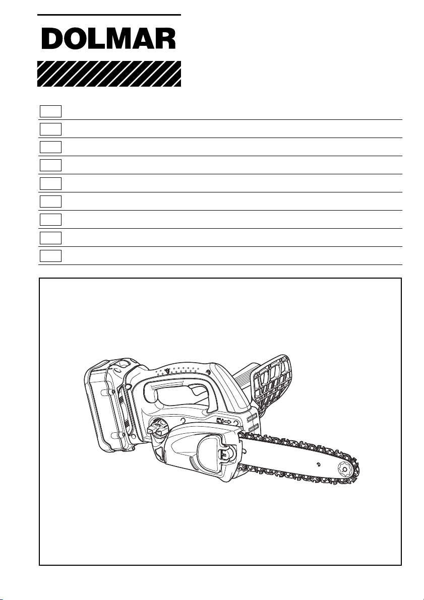
GR Αλυσοπρίονο µπαταρίασ Οδηγίεσ χρήσεωσ
Cordless Chain Saw Instruction Manual
Tronçonneuse sans Fil Manuel d’instructions
Akku-Kettensäge Betriebsanleitung
Motosega a batteria Istruzioni per l’uso
Accu-kettingzaag Gebruiksaanwijzing
Electrosierra Inalámbrica Manual de instrucciones
Motosserra a Bateria Manual de instruções
Akku-kædesav Brugsanvisning
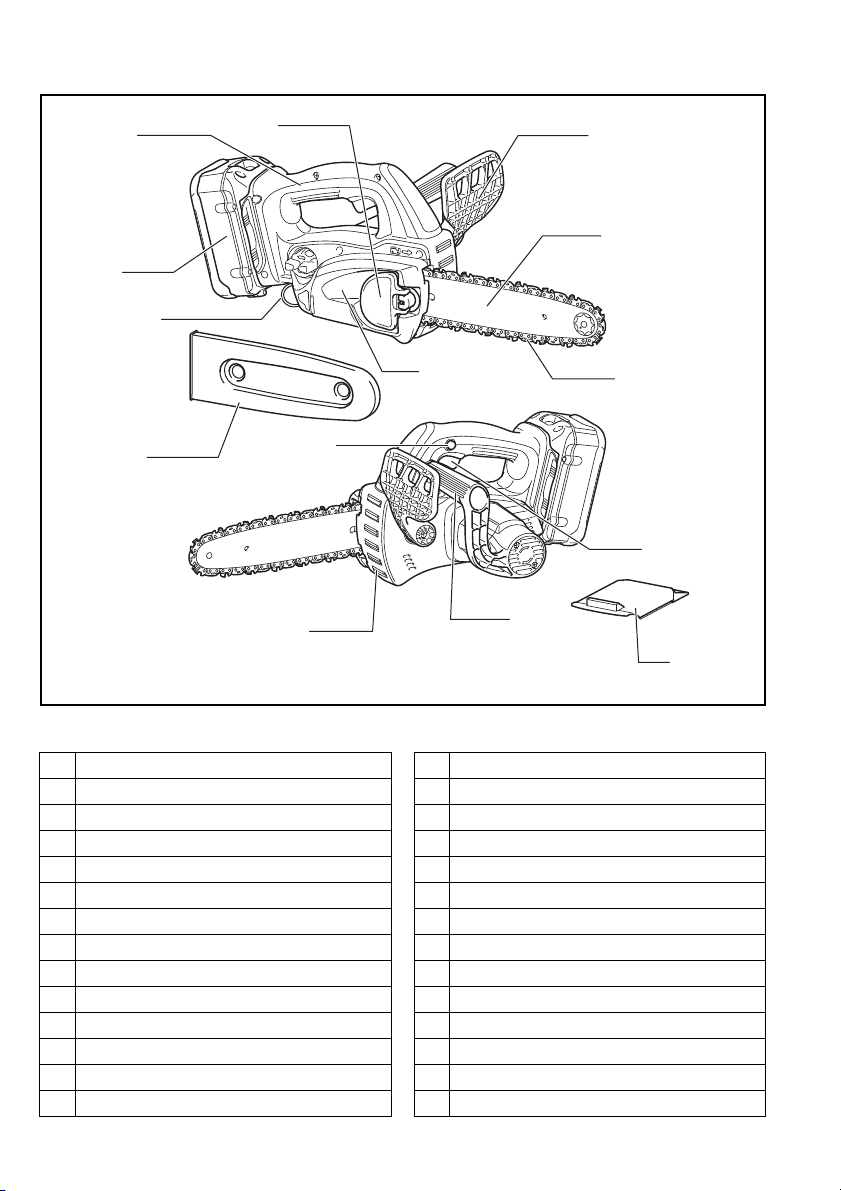
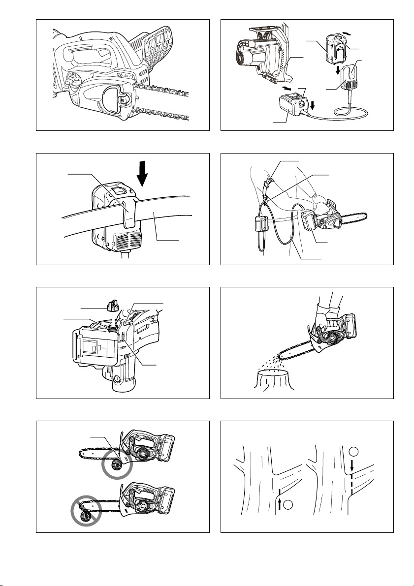
PARTS DESCRIPTION / DESCRIPTION DES PIÈCES / BESCHREIBUNG DER TEILE /
DESCRIZIONE DELLE PARTI / BESCHRIJVING VAN ONDERDELEN / DESCRIPCIÓN DE LAS PARTES /
DESCRIÇÃO DAS PEÇAS / BESKRIVELSE AF DELE / ΠΕΡΙΓΡΑΦΗ ΤΩΝ ΕΞΑΡΤΗΜΑΤΩΝ
3
1
2
6
4
5
8
9
10
7
11
13
12
14
ENGLISH FRANÇAIS
1Lever
2 Front hand guard
3 Top handle
4 Battery cartridge
5 Carabiner or rope attachment point
6 Guide bar
7Saw chain
8 Sprocket cover
9Chain cover
10 Lock off button
11 Switch trigger
12 Front handle
13 Serrated rail (claw stop)
14 Battery cover
2
1Levier
2 Protège-main avant
3 Poignée supérieure
4 Batterie
5 Point de fixation du mousqueton ou de la corde
6 Guide de chaîne
7 Chaîne
8 Couvre-pignon
9 Cache de chaîne
10 Bouton de sécurité
11 Gâchette
12 Poignée avant
13 Rail dentelé (butée à griffe)
14 Couvercle de batterie

DEUTSCH
1 Hebel
2 Vorderer Handschutz
3Obergriff
4 Akku
5 Befestigungsöse für Karabinerhaken oder Seil
6Schwert
7 Sägekette
8 Kettenraddeckel
9 Kettenabdeckung
10 Einschaltarretierung
11 Schalter
12 Frontgriff
13 Krallenanschlag (Klauenanschlag)
14 Akkuabdeckung
NEDERLANDS
1 Hendel
2 Beschermkap van voorhandgreep
3 Bovenhandgreep
4 Accu
5 Bevestigingsoog voor karabijnhaak of touw
6 Zaagblad
7 Zaagketting
8 Afdekking van kettingwiel
9 Kettingdeksel
10 Ontgrendelknop
11 Trekschakelaar
12 Voorhandgreep
13 Getande kam (klauwaanslag)
14 Deksel van de accu
ITALIANO
1Leva
2 Protezione mano anteriore
3 Manico superiore
4 Cartuccia batteria
5 Gancio o punto di attacco fune
6 Barra guida
7 Catena sega
8 Coperchio rocchetto
9 Coperchio catena
10 Bottone di sblocco
11 Interruttore a grilletto
12 Manico anteriore
13 Guida dentata (fermo dente)
14 Coperchio batteria
ESPAÑOL
1Baja
2 Protector de la mano delantera
3 Empuñadura principal
4 Cartucho de batería
5 Punto de sujeción de mosquetón o cuerda
6 Placa de guía
7 Cadena de sierra
8 Cubierta del piñón
9 Cubierta de la cadena
10 Botón de seguro
11 Gatillo interruptor
12 Empuñadura delantera
13 Riel dentado (tope de gancho)
14 Tapa de la batería
3

PORTUGUÊS
1 Alavanca
2 Protector frontal das mãos
3 Pega superior
4 Bateria
5 Ponto de fixação da corda ou gancho
6 Espada
7 Corrente da electroserra
8 Cobertura da roda dentada
9 Cobertura da corrente
10 Botão de bloqueio
11 Gatilho do interruptor
12 Pega frontal
13 Trilho dentado (retentor de garras)
14 Tampa da bateria
DANSK
1Arm
2 Frontkappe
3 Tophåndtag
4 Akku
5 Fastgørelsespunkt til karabinhage eller reb
6Sværd
7 Savkæde
8 Kædehjulsdæksel
9 Kædedæksel
10 Låseknap
11 Afbryderknap
12 Fronthåndtag
13 Takket kant (hage-stop)
14 Batteridæksel
ΕΛΛΗΝΙΚΑ
1 Μοχλσ
2 Μπροστινσ προφυλακτήρασ χεριών
3 Άνω λαβή
4 Κασετίνα µπαταρίασ
5 Carabiner ή σηµείο πρσδεσησ σχοινιού
6 Κατευθυντήρια λάµα
7 Αλυσίδα πριονιού
8 Κάλυµµα οδοντωτού τροχού
9 Κάλυµµα αλυσίδασ
10 Πλήκτρο ασφάλειασ
11 Σκανδάλη διακπτησ
12 Μπροστινή λαβή
13 Οδοντωτή ράγα (στοπ σιαγνασ)
14 Κάλυµµα µπαταρίασ
4
12
10
4
5
9
78
6
1
2
3
10
4
5
9
78
6
1
2
3
34
11
11
12
12
56
78
15
17
18
18
17
13
13
14
14
15
16
16
5
22
15
16
15
22
27
26
18
24
25
2 - 4 mm
23
21
19
15
16
20
910
11 12
13 14
15 16
6
17 18
29
31
1
2
40
3
2
29
28
30
2
28
37
36
39
38
32
33
34
35
19 20
21 22
23 24
7
25 26
45
o
2 1/2
45
o
41
A
B
A
B
27 28
29 30
31 32
8
33 34
48
49
45
3
46
47
42
43
43
44
44
35 36
37 38
39 40
9
41 42
52
53
51
50
19
19
50
43 44
45
10

Symbols
The followings show the symbols used for the equipment. Be sure that you understand their meaning before use.
Symboles
Nous donnons ci-dessous les symboles utilisés pour l’outil. Assurez-vous que vous en avez bien compris la signification avant d’utiliser l’outil.
Symbole
Die folgenden Symbole werden für die Maschine verwendet. Machen Sie sich vor der Benutzung unbedingt mit ihrer
Bedeutung vertraut.
Simboli
Per questo utensile vengono usati i simboli seguenti. Bisogna capire il loro significato prima di usare l’utensile.
Symbolen
Voor dit gereedschap worden de volgende symbolen gebruikt. Zorg ervoor dat u de betekenis van deze symbolen
begrijpt alvorens het gereedschap te gebruiken.
Símbolos
A continuación se muestran los símbolos utilizados con esta herramienta. Asegúrese de que entiende su significado
antes de usarla.
Símbolos
O seguinte mostra os símbolos utilizados para a ferramenta. Certifique-se de que compreende o seu significado antes
da utilização.
Symboler
Nedenstående symboler er anvendt i forbindelse med denne maskine. Vær sikker på, at De har forstået symbolernes
betydning, før maskinen anvendes.
Σύµβολα
Τα ακλουθα δείχνουν τα σύµβολα που χρησιµοποιούνται για το µηχάνηµα. Βεβαιωθείτε τι καταλαβαίνετε
τη σηµασία τουσ πριν απ τη χρήση.
END005-4
• Read instruction manual.
• Lire le mode d’emploi.
• Bitte Bedienungsanleitung lesen.
• Leggete il manuale di istruzioni.
• Lees de gebruiksaanwijzing.
• Lea el manual de instrucciones.
• Leia o manual de instruções.
• Læs brugsanvisningen.
• ∆ιαβάστε τισ οδηγίεσ χρήσησ.
• Wear eye protection.
• Portez une protection pour les yeux.
• Eine Schutzbrille tragen.
• Indossare gli occhiali di protezione.
• Draag oogbescherming.
• Póngase protección para los ojos.
• Utilize protectores para os olhos.
• Brug øjenbeskyttelse.
• Να φοράτε προστατευτικά µατιών.
11

• Wear ear protection.
• Portez une protection pour les oreilles.
• Einen Gehörschutz tragen.
• Indossare la protezione delle orecchie.
• Draag gehoorbescherming.
• Póngase protección para los oídos.
• Utilize protectores para os ouvidos.
• Brug høreværn.
• Να φοράτε προστατευτικά αυτιών.
• Wear a helmet, goggles and ear protection.
• Portez un casque, des lunettes de sécurité et une protection pour les oreilles.
• Tragen Sie einen Helm, eine Schutzbrille und einen Gehörschutz.
• Indossare il casco, gli occhiali di protezione e i paraorecchi.
• Draag een veiligheidshelm, veiligheidsbril en oorbescherming.
• Póngase casco, gafas de seguridad y protección para los oídos.
• Use um capacete, óculos de segurança e protectores para os ouvidos.
• Bær hjelm, sikkerhedsbriller og høreværn.
• Να φοράτε κράνσ και µέσα προστασίασ ρασησ και ακήσ.
• Do not expose to rain.
• N’exposez pas l’outil à la pluie.
• Die Maschine keinem Regen aussetzen.
• Non esporre alla pioggia.
• Stel het gereedschap niet bloot aan regen.
• No exponga a la lluvia.
• Não exponha a ferramenta à chuva.
• Udsæt ikke saven for regn.
• Να µην εκτίθεται στη βροχη.
12
• Hold the saw with both hands while working! One-handed use is extremely hazardous!
• Tenez la scie fermement à deux mains pendant que vous travaillez ! L’utilisation avec une
seule main est extrêmement dangereuse !
• Die Säge während der Arbeit mit beiden Händen halten! Einhändiger Betrieb ist äußerst
gefährlich!
• Tenere la sega con entrambe le mani durante il lavoro! L’uso con una sola mano è estremamente pericoloso!
• Houd de kettingzaag tijdens het werk met beide handen vast! Gebruik met slechts één hand
is uitermate gevaarlijk.
• ¡Sujete la sierra con ambas manos mientras realiza el trabajo! ¡La utilización una sola mano
es muy peligroso!
• Segure a electroserra com as duas mãos ao trabalhar. É muito perigoso segurá-la só com
uma mão.
• Hold i saven med begge hænder under arbejdet! Anvendelse med kun den ene hånd på
saven er yderst farligt!
• Να κρατάτε τ αλυσοπρίονο µε τα δύο χέρια στη διάρκεια τησ εργασίασ! Η χρήση µε το
χένα έρι είναι εξαιρετικά επικίνδυνη!
• Maximum permissible cut length
• Longueur de coupe maximale admise
• Höchstzulässige Schnittlänge
• Lunghezza di taglio massima permissibile
• Maximaal toegestane zaaglengte
• Longitud de corte permitida máxima
• Comprimento máximo de corte permitido
• Maks. tilladt skærelængde
• Μέγιστο επιτρεποµενο µήκοσ κοπήσ
• Direction of chain travel
• Sens de progression de la chaîne
• Kettenumlaufrichtung
• Direzione di corsa catena
• Draairichting van de ketting
• Dirección de desplazamiento de la cadena
• Sentido de movimento da corrente
• Retning af kædens bevægelse
• Κατεύθυνση διαδροµήσ αλυσίδασ
13

• Saw chain oil adjustment
Cd
Ni-MH
Li-ion
• Réglage d’huile de la chaîne
• Sägekettenöleinstellung
• Regolazione olio catena sega
• Afstelling voor zaagkettingolie
• Ajuste del aceite de la cadena de sierra
• Regulação da lubrificação da corrente da electroserra
• Justering af savkædeolie
• Ρύθµιση λίπανσησ αλυσίδασ αλυσοπρίονου
• Only for EU countries
Do not dispose of electric equipment or battery pack together with household waste material!
In observance of European Directive 2002/96/EC on waste electric and electronic equipment, 2006/
66/EC on batteries and accumulators and waste batteries and accumulators and their implementation in accordance with national laws, electric equipment and battery pack that have reached the
end of their life must be collected separately and returned to an environmentally compatible recycling facility.
• Uniquement pour les pays de l’UE
Ne pas jeter les appareils électriques et les batteries avec les ordures ménagères !
Conformément aux directives européennes 2002/96/CE (relative aux déchets d’équipements électriques et électroniques) et 2006/66/CE (relative aux piles et accumulateurs ainsi qu’aux déchets de
piles et accumulateurs), ainsi qu’à leur application en conformité avec les lois nationales, les appareils électriques et batteries qui ont atteint la fin de leur durée de service doivent être collectés
séparément et renvoyés à un établissement de recyclage respectueux de l’environnement.
• Nur für EG-Länder
Werfen Sie Elektrogeräte oder Akkus nicht in den Hausmüll!
Gemäß der Europäischen Richtlinie 2002/96/EG über Elektro- und Elektronik-Altgeräte, 2006/66/
EG über Batterien, Akkus sowie verbrauchte Batterien und Akkus und ihre Umsetzung gemäß den
Landesgesetzen müssen Elektrogeräte und Akkus, die das Ende ihrer Lebensdauer erreicht haben,
getrennt gesammelt und einer umweltgerechten Recycling-Einrichtung zugeführt werden.
• Soltanto per i Paesi dell'unione europea
Questo apparecchio elettrico o la batteria non devono essere gettati via con i rifiuti domestici.
In osservanza alla Direttiva Europea 2002/96/CE sugli apparecchi elettrici ed elettronici di scarto,
2006/66/CE sulle batterie e gli accumulatori, e sulle batterie e gli accumulatori esausti, e la sua
implementazione secondo le leggi locali, gli apparecchi elettrici e le batterie che hanno raggiunto la
fine della loro vita di servizio devono essere raccolti separatamente e portati in un centro di smaltimento ecocompatibile.
• Alleen voor EU-landen
Geef elektrisch gereedschap of accu's niet met het huisvuil mee!
Volgens de Europese richtlijn 2002/96/EC inzake oude elektrische en elektronische apparaten, richtlijn 2006/66/EC inzake batterijen en accu's en wegwerpbatterijen, en de toepassing daarvan binnen de nationale wetgeving, dienen gebruikte elektrisch apparaten en accu's die het einde van hun
levensduur hebben bereikt, gescheiden te worden ingezameld en te worden afgevoerd naar een
recyclebedrijf dat voldoet aan de geldende milieu-eisen.
• Sólo para países de la Unión Europea
¡No tire aparatos eléctricos ni baterías a la basura con los residuos domésticos!
En conformidad con la Directiva Europea 2002/96/EC sobre residuos de aparatos eléctricos y electrónicos y la Directiva Europea 2006/66/EC sobre baterías y acumuladores y residuos de baterías y
de acumuladores y su aplicación de acuerdo con la legislación nacional, los aparatos eléctricos y
las baterías cuya vida útil haya llegado a su fin se deberán recoger por separado y trasladar a una
planta de reciclaje que cumpla con las exigencias ecológicas.
14

• Apenas para os países da União Européia
Não deite equipamentos eléctricos nem baterias no lixo doméstico!
De acordo com as directivas europeias 2002/96/CE sobre ferramentas eléctricas e electrónicas
usadas e 2006/66/CE sobre baterias e acumuladores e respectivos resíduos e a implementação
dessas directivas conforme a lei nacional, as ferramentas eléctricas e as baterias que atingem o fim
de sua vida útil devem ser recolhidas em separado e encaminhadas a uma instalação de reciclagem compatível com os regulamentos sobre o meio ambiente.
• Gælder kun lande i EU
Undlad at bortskaffe elektrisk udstyr eller akkuer sammen med almindeligt husholdningsaffald.
I henhold til EU-direktiv 2002/96/EC angående brugt elektrisk og elektronisk udstyr, 2006/66/EC
angående batterier og akkumulatorer og brugte batterier og iværksættelse af bortskaffelse af batterier og akkumulatorer i overensstemmelse med nationale love, skal elektrisk udstyr og akkuer, der
har nået slutningen af deres levetid, indsamles separat og afhændes til en genbrugsfacilitet, som er
miljømæssigt kompatibel.
• Μνο για χώρεσ ΕΕ
Μην απορρίπτετε ηλεκτρικ εξοπλισµ ή µπαταρίεσ µαζί µε τα οικιακά απβλητα!
Σύµφωνα µε την Ευρωπαϊκή Οδηγία 2002/96/ΕΚ περί αποβλήτων ειδών ηλεκτρικού και
ηλεκτρονικού εξοπλισµού και την Οδηγία 2006/66/EΚ περί µπαταριών και συσσωρευτών και
αποβλήτων µπαταριών και συσσωρευτών και την εφαρµογή τουσ σύµφωνα µε την εθνική
νοµοθεσία, απαιτείται συλλογή του ηλεκτρικού εξοπλισµού και των µπαταριών, το ριο
ζωήσ των οποίων έχει λήξει, ξεχωριστά και επιστροφή τουσ σε εγκατάσταση ανακύκλωσησ
συµβατή µε την προστασία του περιβάλλοντοσ.
15

ENGLISH (Original instructions)
Explanation of general view
1Red part
2Button
3 Battery cartridge
4 Lock-off button
5 Switch trigger
6 Front hand guard
7Lock
8 Unlock
9 Adjusting screw
10 Carabiner
(rope attachment point)
11 Indicator lamps
12 CHECK button
13 Slightly slide
14 Move in the upright position
15 Press in
16 Loosen
17 Sprocket cover
18 Adjusting dial
SPECIFICATIONS
Model AS-3625 AS-3626
Chain speed per minute 8.3 m/s (500 m/min) 8.3 m/s (500 m/min)
Length of guide bar 250 mm 250 mm
Guide bar type
Type 91VG 25AP 91VG 25AP
Saw chain
Pitch 3/8”1/4”3/8”1/4”
No. of drive links 40 60 40 60
Number of teeth 6 9 6 9
Overall length 576 mm 589 mm 577 mm 590 mm
Net weight 4.5 kg 4.5 kg
Rated voltage D.C. 36 V D.C. 36 V
• Weight, with battery cartridge, according to EPTA-Pro-
cedure 01/2003
Intended use
The tool is intended for cutting lumbers and logs.
General Power Tool Safety Warnings
WARNING Read all safety warnings and all
instructions. Failure to follow the warnings and
instructions may result in electric shock, fire and/or
serious injury.
Save all warnings and instructions for future reference.
19 Sprocket
20 Adjusting pin
21 Small hole
22 Tighten
23 Lever
24 Low
25 High
26 Guide bar
27 Saw chain
28 Adapter
29 Hook
30 Tool
31 Belt
32 Arm cord hook band
33 Holder
34 Extension cord (Battery
adapter)
35 Adapter (Battery adapter)
36 Oil tank cap
Sprocket nose
bar
ENE031-1
GEA010-1
Carving bar
CORDLESS CHAIN SAW SAFETY WARNINGS:
1. Keep all parts of the body away from the saw
chain when the chain saw is operating. Before
you start the chain saw, make sure the saw chain
is not contacting anything. A moment of inatten-
tion while operating chain saws may cause entanglement of your clothing or body with the saw chain.
2. Always hold the chain saw with your right hand
on the rear handle and your left hand on the
front handle. Holding the chain saw with a reversed
hand configuration increases the risk of personal
injury and should never be done.
3. Hold the power tool by insulated gripping surfaces only, because the saw chain may contact
hidden wiring. Saw chains contacting a “live” wire
may make exposed metal parts of the power tool
“live” and could give the operator an electric shock.
37 Oil tank opening
38 Oil inspection window
(for refilling the tank with oil)
39 Oil inspection window
40 Lower guide
41 Felling area
42 Felling direction
43 Danger zone
44 Escape route
45 Scabbard (chain cover)
46 File forward stroke
47 1/5 of the file diameter
48 Small dust or particles
49 Slotted bit screwdriver
50 Locking ring
51 Limit mark
52 Brush holder cap
53 Screwdriver
Sprocket nose
bar
Carving bar
GEB071-5
16
4. Wear safety glasses and hearing protection. Further protective equipment for head, hands, legs
and feet is recommended. Adequate protective
clothing will reduce personal injury by flying debris
or accidental contact with the saw chain.
5. Before starting work, check that the chain saw is in
proper working order and that its condition complies
with the safety regulations. Check in particular that:
• The chain brake is working properly;
• The run-down brake is working properly;
• The bar and the sprocket cover are fitted cor-
rectly;
• The chain has been sharpened and tensioned in
accordance with the regulations;
6. Do not operate a chain saw in a tree. Operation of
a chain saw while up in a tree may result in personal
injury.
7. Always keep proper footing and operate the
chain saw only when standing on fixed, secure
and level surface. Slippery or unstable surfaces
such as ladders may cause a loss of balance or control of the chain saw.
8. When cutting a limb that is under tension be
alert for spring back. When the tension in the wood
fibres is released the spring loaded limb may strike
the operator and/or throw the chain saw out of control.
9. Use extreme caution when cutting brush and
saplings. The slender material may catch the saw
chain and be whipped toward you or pull you off balance.
10. Carry the chain saw by the front handle with the
chain saw switched off and away from your body.
When transporting or storing the chain saw
always fit the guide bar cover. Proper handling of
the chain saw will reduce the likelihood of accidental
contact with the moving saw chain.
11. Follow instructions for lubricating, chain tensioning and changing accessories. Improperly
tensioned or lubricated chain may either break or
increase the chance for kickback.
12. Keep handles dry, clean, and free from oil and
grease. Greasy, oily handles are slippery causing
loss of control.
13. Cut wood only. Do not use chain saw for purposes not intended. For example: do not use
chain saw for cutting plastic, masonry or nonwood building materials. Use of the chain saw for
operations different than intended could result in a
hazardous situation.
14. Causes and operator prevention of kickback:
Kickback may occur when the nose or tip of the
guide bar touches an object, or when the wood
closes in and pinches the saw chain in the cut.
Tip contact in some cases may cause a sudden
reverse reaction, kicking the guide bar up and back
towards the operator.
Pinching the saw chain along the top of the guide
bar may push the guide bar rapidly back towards the
operator.
Either of these reactions may cause you to lose control of the saw which could result in serious personal
injury. Do not rely exclusively upon the safety
devices built into your saw. As a chain saw user, you
should take several steps to keep your cutting jobs
free from accident or injury.
Kickback is the result of tool misuse and/or incorrect
operating procedures or conditions and can be
avoided by taking proper precautions as given
below:
- Maintain a firm grip, with thumbs and fingers
encircling the chain saw handles, with both hands
on the saw and position your body and arm to
allow you to resist kickback forces. Kickback
forces can be controlled by the operator, if proper
precautions are taken. Do not let go of the chain
saw.
- Do not overreach and do not cut above shoul-
der height. This helps prevent unintended tip
contact and enables better control of the chain
saw in unexpected situations.
- Only use replacement bars and chains speci-
fied by the manufacturer. Incorrect replacement
bars and chains may cause chain breakage and/
or kickback.
- Follow the manufacturer’s sharpening and
maintenance instructions for the saw chain.
Decreasing the depth gauge height can lead to
increased kickback.
15. Do not start the chain saw with the chain cover
being installed on it. Starting the chain saw with
the chain cover being installed on it may cause the
chain cover to thrown out forward resulting in personal injury and damage to objects around the operator.
SAVE THESE INSTRUCTIONS.
WARNI NG:
DO NOT let comfort or familiarity with product
(gained from repeated use) replace strict adherence
to safety rules for the subject product. MISUSE or
failure to follow the safety rules stated in this instruction manual may cause serious personal injury.
17

ENC007-6
IMPORTANT SAFETY INSTRUCTIONS
FOR BATTERY CARTRIDGE
1. Before using battery cartridge, read all instructions and cautionary markings on (1) battery
charger, (2) battery, and (3) product using battery.
2. Do not disassemble battery cartridge.
3. If operating time has become excessively
shorter, stop operating immediately. It may
result in a risk of overheating, possible burns
and even an explosion.
4. If electrolyte gets into your eyes, rinse them out
with clear water and seek medical attention right
away. It may result in loss of your eyesight.
5. Do not short the battery cartridge:
(1) Do not touch the terminals with any conduc-
tive material.
(2) Avoid storing battery cartridge in a container
with other metal objects such as nails, coins,
etc.
(3) Do not expose battery cartridge to water or
rain.
A battery short can cause a large current flow,
overheating, possible burns and even a breakdown.
6. Do not store the tool and battery cartridge in
locations where the temperature may reach or
exceed 50°C (122°F).
7. Do not incinerate the battery cartridge even if it
is severely damaged or is completely worn out.
The battery cartridge can explode in a fire.
8. Be careful not to drop or strike battery.
9. Do not use dropped or struck battery.
SAVE THESE INSTRUCTIONS.
Tips for maintaining maximum battery life
1. Charge the battery cartridge before completely
discharged.
Always stop tool operation and charge the battery cartridge when you notice less tool power.
2. Never recharge a fully charged battery cartridge.
Overcharging shortens the battery service life.
3. Charge the battery cartridge with room temperature at 10°C – 40°C (50°F – 104°F). Let a hot battery cartridge cool down before charging it.
FUNCTIONAL DESCRIPTION
CAUTION:
• Always be sure that the tool is switched off and the battery cartridge is removed before adjusting or checking
function on the tool.
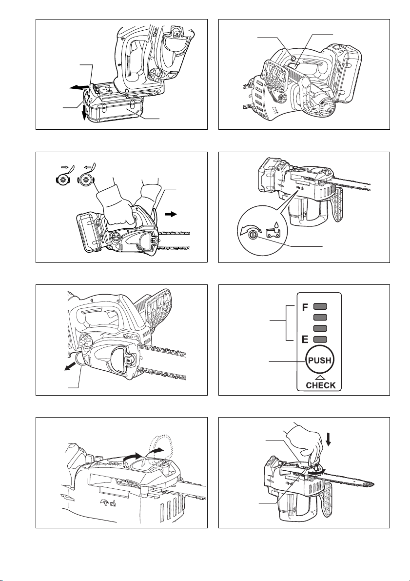
Installing or removing battery cartridge (Fig. 1)
CAUTION:
• Hold the tool and the battery cartridge firmly when
installing or removing battery cartridge. Failure to
hold the tool and the battery cartridge firmly may cause
them to slip off your hands and result in damage to the
tool and battery cartridge and a personal injury.
• Always switch off the tool before installing or removal of
the battery cartridge.
• To remove the battery cartridge, withdraw it from the
tool while sliding the button on the front of the cartridge.
• To insert the battery cartridge, align the tongue on the
battery cartridge with the groove in the housing and slip
it into place. Always insert it all the way until it locks in
place with a little click. If you can see the red part on
the upper side of the button, it is not locked completely.
Insert it fully until the red part cannot be seen. If not, it
may accidentally fall out of the tool, causing injury to
you or someone around you.
• Do not use force when inserting the battery cartridge. If
the cartridge does not slide in easily, it is not being
inserted correctly.
Switch action (Fig. 2)
CAUTION:
• Before inserting the battery cartridge into the tool,
always check to see that the switch trigger actuates
properly and returns to the “OFF” position when
released.
To prevent the switch trigger from being accidentally
pulled, a lock-off button is provided.
To start the tool, depress the lock-off button and pull the
switch trigger. Release the switch trigger to stop.
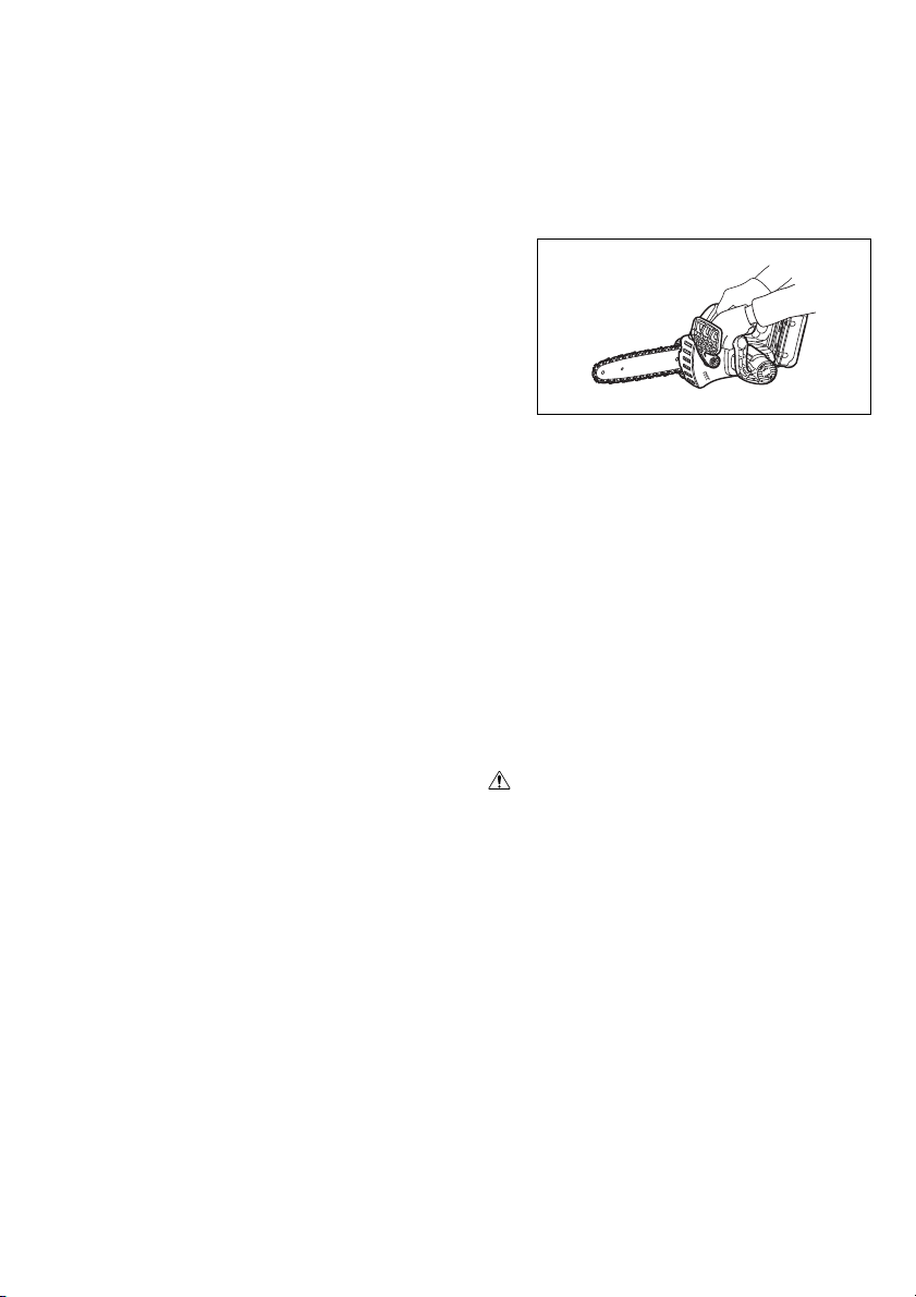
Checking the chain brake (Fig. 3)
NOTE:
• If the chain saw fails to start, the chain brake must be
released. Pull the front hand guard backwards firmly
until you feel it engage.
Hold the chain saw with both hands when switching it on.
Hold the top handle with your right hand, the front handle
with your left. The bar and the chain must not be in contact with any object.
First press the lock-off button, then the switch trigger.
The saw chain starts immediately.
Press the front hand guard forwards using the back of
your hand. The saw chain must come to an immediate
standstill.
CAUTION:
• Should the saw chain not stop immediately when this
test is performed, the saw may not be used under any
circumstances. Consult a DOLMAR specialist repair
shop.
18
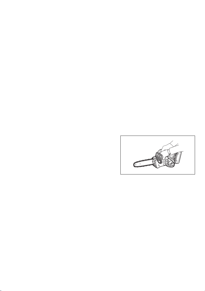
Checking the run-down brake
Lighted
Off
Blinking
E
F
Switch on the chain saw.
Release the switch trigger completely. The saw chain
must come to a standstill within one second.
CAUTION:
• Should the saw chain not come to a stop within one
second when this test is performed, the saw must not
be used. Consult a DOLMAR specialist repair shop.
Adjusting the chain lubrication (Fig. 4)
You can adjust the oil pump feed rate with the adjusting
screw. The amount of oil can be adjusted using the universal wrench.
Carabiner (rope attachment point) (Fig. 5)
Carabiner (Rope attachment point) is for use of tool
hanging. Before using carabiner, pull it out and tie it with
a rope.
Battery protection system
The tool is equipped with the protection system, which
automatically cuts off the output power for its long service
life.
The tool may stop during operation when the tool and/or
battery are placed under the following situation. This is
caused by the activation of protection system and does
not show the tool trouble.
• When the tool is overloaded:
At this time, release the switch trigger and remove
causes of overload and then pull the switch trigger
again to restart. When the tool does not work even
after pulling the switch trigger, the battery power
auto-stop is still at work. Charge the battery cartridge before use.
• When the remaining battery capacity becomes low:
Recharge the battery cartridge.
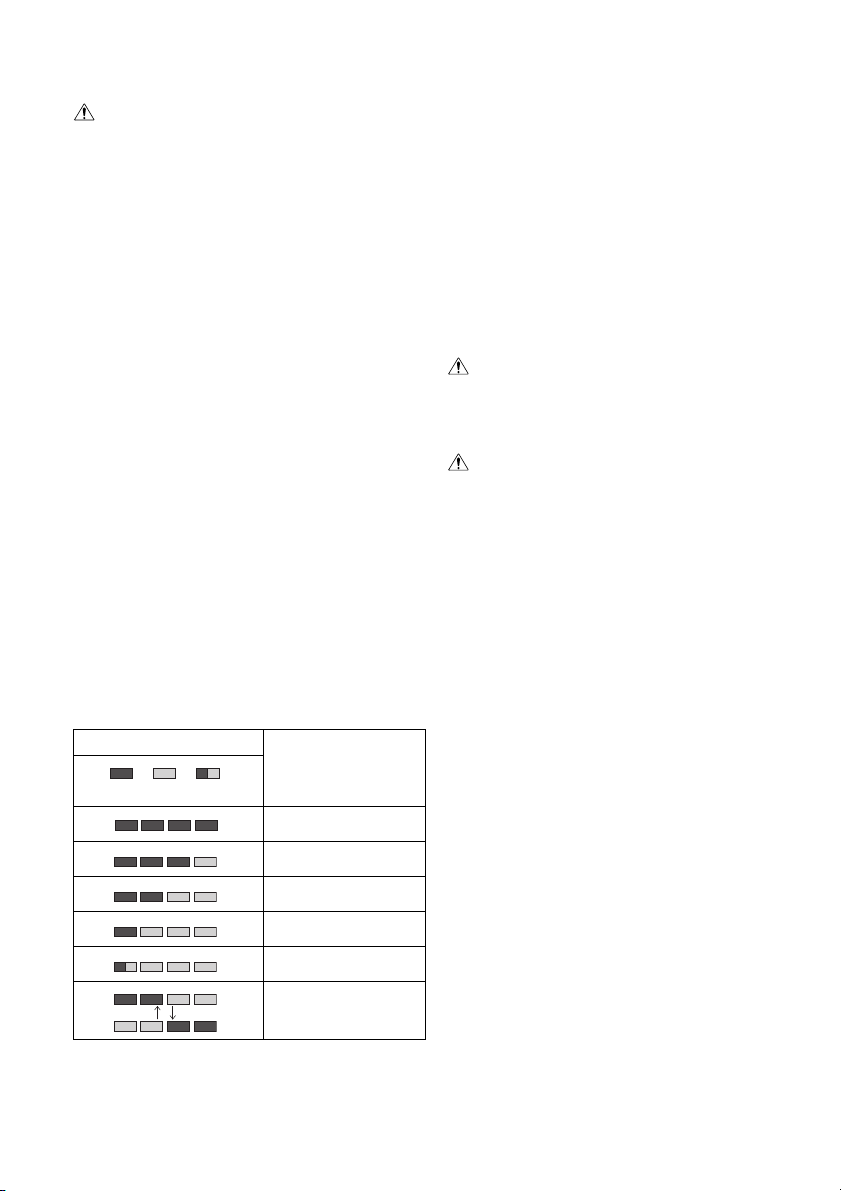
Battery remaining capacity indicator (only for
models with Battery AP-3622)
Battery AP-3622 is equipped with the battery remaining
capacity indicator. (Fig. 6)
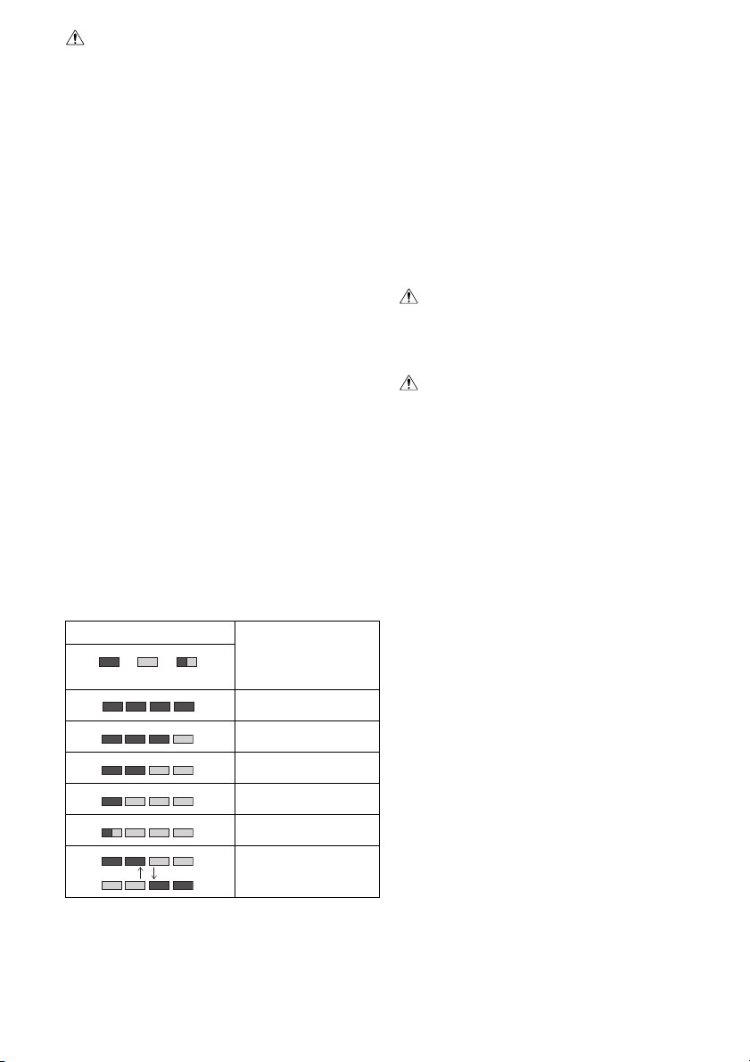
Press the CHECK button to indicate the battery remaining capacity. The indicator lamps will then light for
approx. three seconds.
Indicator lamps
Remaining capacity
70% to 100%
45% to 70%
20% to 45%
0% to 20%
Charge the battery.
The battery may have
malfunctioned.
• When only the lowermost indicator lamp (next to the
“E”) blinks, or when none of the indicator lamps light,
the battery charge has run out, so the tool does not
operate. In these cases, charge the battery or replace
the empty battery with a fully charged one.
• When two or more indicator lamps do not light even
after charging is complete, the battery has reached the
end of its service life.
• When the upper two and lower two indicator lamps light
alternately, the battery may have malfunctioned. Contact your local DOLMAR authorized service center.
NOTE:
• The indicated charge may be lower than the actual
level during use or immediately after using the tool.
• Depending on the conditions of use and the ambient
temperature, the indication may differ slightly from the
actual capacity.
ASSEMBLY
CAUTION:
• Always be sure that the tool is switched off and the battery cartridge is removed before carrying out any work
on the tool.
Installing or removing saw chain
CAUTION:
• Always be sure that the tool is switched off and the battery cartridge is removed before installing or removing
the saw chain.
• Always wear gloves when installing or removing the
saw chain.
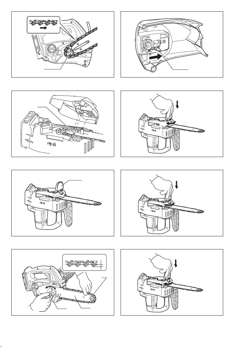
1. To remove the saw chain, slightly slide the lever in
the direction of arrow so that it can be released from
the locked position and move the lever in the upright
position as shown in the figure. (Fig. 7)
2. Press the lever and with the lever pressed in, turn it
counterclockwise to loosen the nut until sprocket
cover comes off. (Pressing in the lever leads to the
fitting of lever into the nut.) (Fig. 8)
3. Turn the adjusting dial counterclockwise to release
the saw chain tension.
4. Remove the sprocket cover.
5. Remove the saw chain and guide bar from the chain
saw.
6. To install the saw chain, fit in one end of the saw
chain on the top of the guide bar and the other end
of it around the sprocket. (Fig. 9)
At this time, fit the saw chain as shown in the figure
because it rotates in the direction of arrow.
7. Rest the guide bar in place on the chain saw.
8. Turn the adjusting dial counterclockwise to slide the
adjusting pin in the direction of arrow. (Fig. 10)
9. Place the sprocket cover on the chain saw so that
the adjusting pin is positioned in a small hole in the
guide bar. (Fig. 11)
10. Press in the lever and with the lever depressed turn
it fully clockwise to tighten the nut. Then make it
about a quarter turn counterclockwise to loosen the
nut lightly. (Fig. 12)
19

Adjusting saw chain tension
The saw chain may become loose after many hours of
use. From time to time check the saw chain tension
before use. (Fig. 13)
Move the lever in the upright position.
Press in the lever. With the lever depressed, make a
quarter turn on it counterclockwise to loosen the nut
lightly. (Pressing in the lever leads to the fitting of lever
into the nut.) (Fig. 14)
Turn the adjusting dial to adjust saw chain tension. Grasp
the saw chain in the middle of the guide bar and lift up.
The gap between the guide bar and the tie strap of the
saw chain should be approx. 2 – 4 mm. If the gap is not
approx. 2 – 4 mm, slightly turn the adjusting dial which
secures the guide bar. At this time, adjust with the tip of
guide bar slightly pointing up. (Fig. 15)
With the lever depressed, turn it fully clockwise to tighten
the nut firmly. (Fig. 16)
Return the lever to its original position. (Fig. 17)
CAUTION:
• Excessively high tension of saw chain may cause
breakage of saw chain, wear of the guide bar and
breakage of the adjusting dial.
• Installing or removing saw chain should be carried out
in a clean place free from sawdust and the like.
Battery adapter (Accessory) (Fig. 18 & 19)
CAUTION:
• Before using battery adapter, read all instructions on
tools using battery.
• When charging a battery cartridge, first remove it from
the battery adapter and then charge it. It is not allowed
to charge the battery cartridge while using battery
adapter.
Installing or removing battery adapter
• Always switch off the tool before insertion or removal of
the battery adapter.
• To remove the battery adapter, withdraw it from the tool
while sliding the button on the adapter.
• To insert the battery adapter, align the tongue on the
battery adapter with the groove in the housing and slip
it into place. Always insert it all the way until it locks in
place with a little click. If you can see the red part on
the upper side of the button, it is not locked completely.
Insert it fully until the red part cannot be seen. If not, it
may accidentally fall out of the tool, causing injury to
you or someone around you.
• Do not use force when inserting the battery adapter. If
the adapter does not slide in easily, it is not being
inserted correctly.
• The way of removing or installing a battery cartridge
from or on the battery adapter is the same as that of
removing or installing it from or on the tools.
• Press down the hook securely as far as it will go when
the battery adapter is hooked on the waist belt and similar objects.
Arm cord hook (Accessory) (Fig. 20)
CAUTION:
• Do not attach the holder of arm cord hook to other than
the extension cord. Failure to do so may cause an accident or personal injury.
Using the arm cord hook helps to minimize a risk of cutting off the extension cord unexpectedly caused by the
loose extension cord.
Attach firmly the arm cord hook band placing around
your arm and pass the extension cord through the holder.
The length of the arm cord hook band is adjustable.
NOTE:
• Do not pass the extension cord through the band.
• Do not force the opening of the holder. Failure to do so
may cause deflection and damage to it.
OPERATION
Lubrication (Fig. 21)
Saw chain is automatically lubricated when the tool is in
operation.
Check the amount of remaining oil in the oil tank through
the oil inspection window.
To refill the tank, remove the cap from the oil tank opening. The oil tank capacity is 85 ml.
After refilling the tank, always screw the provided oil tank
cap on the chain saw.
CAUTION:
• When filling the chain saw with chain oil for the first
time, or refilling the tank after it has been completely
emptied, add oil up to the bottom edge of the filler neck.
The oil delivery may otherwise be impaired.
• As a saw chain oil, use oil exclusively for Dolmar chain
saws or oil available in market.
• Never use oil including dust and particles or volatile oil.
• When pruning trees, use botanical oil. Mineral oil may
harm trees.
• Never force the chain saw when pruning trees.
• Before cutting out, make sure that the provided oil tank
cap is screwed in place.
Hold the chain saw away from the tree. Start it and wait
until lubrication on saw chain is adequate.
Bring the lower guide into contact with the branch to be
cut before switching on. Cutting without bringing the
lower guide into contact with the branch may cause the
guide bar to wobble, resulting in injury to operator.
Saw the wood to be cut by just moving it down. (Fig. 22)
20

WORKING WITH THE CHAIN SAW
The first time user should, as a minimum practice, do cutting logs on a saw-horse or cradle.
Pruning trees
CAUTION:
• Keep all parts of the body away from the saw chain
when the motor is operating.
• Hold the chain saw firmly with both hands when the
motor is running.
• Do not overreach. Keep proper footing and balance at
all times.
Bring the lower guide into contact with the branch to be
cut before switching on. Cutting without bringing the
lower guide into contact with the branch may cause the
guide bar to wobble, resulting in injury to operator.
(Fig. 23)
When cutting thick branches, first make a shallow undercut and then make the finish cut from the top. (Fig. 24)
If you try to cut off thick branches from the bottom, the
branch may close in and pinch the saw chain in the cut. If
you try to cut off thick branches from the top without a
shallow undercut, the branch may splinter. (Fig. 25)
If you cannot cut the timber right through with a single
stroke:
Apply light pressure to the handle and continue sawing
and draw the chain saw back a little; then apply the spike
a little lower and finish the cut by raising the handle.
(Fig. 26)
Bucking
For bucking cuts, rest the serrated rail shown in the figure
on the wood to be cut. (Fig. 27)
With the saw chain running, saw into the wood, using the
top handle to raise the saw and the front one to guide it.
Use the serrated rail as a pivot.
Continue the cut by applying slight pressure to the front
handle, easing the saw back slightly. Move the serrated
rail further down the timber and raise the front handle
again.
When making several cuts, switch the chain saw off
between cuts.
CAUTION:
• If the upper edge of the bar is used for cutting, the
chain saw may be deflected in your direction if the
chain becomes trapped. For this reason, cut with the
lower edge, so that the saw will be deflected away from
your body. (Fig. 28)
Cut wood under tension on the pressure side (A) first.
Then make the final cut on the tension side (B). This prevents the bar from becoming trapped. (Fig. 29)
Limbing
CAUTION:
• Limbing may only be performed by trained persons. A
hazard is presented by the risk of kick-back.
When limbing, support the chain saw on the trunk if possible. Do not cut with the tip of the bar, as this presents a
risk of kickback.
Pay particular attention to branches under tension. Do
not cut unsupported branches from below.
Do not stand on the felled trunk when limbing.
Burrowing and parallel-to-grain cuts
CAUTION:
• Burrowing and parallel-to-grain cuts may only be carried out by persons with special training. The possibility
of kickback presents a risk of injury.
Perform parallel-to-grain cuts at as shallow an angle as
possible. Carry out the cut as carefully as possible, as
the serrated rail cannot be used. (Fig. 30)
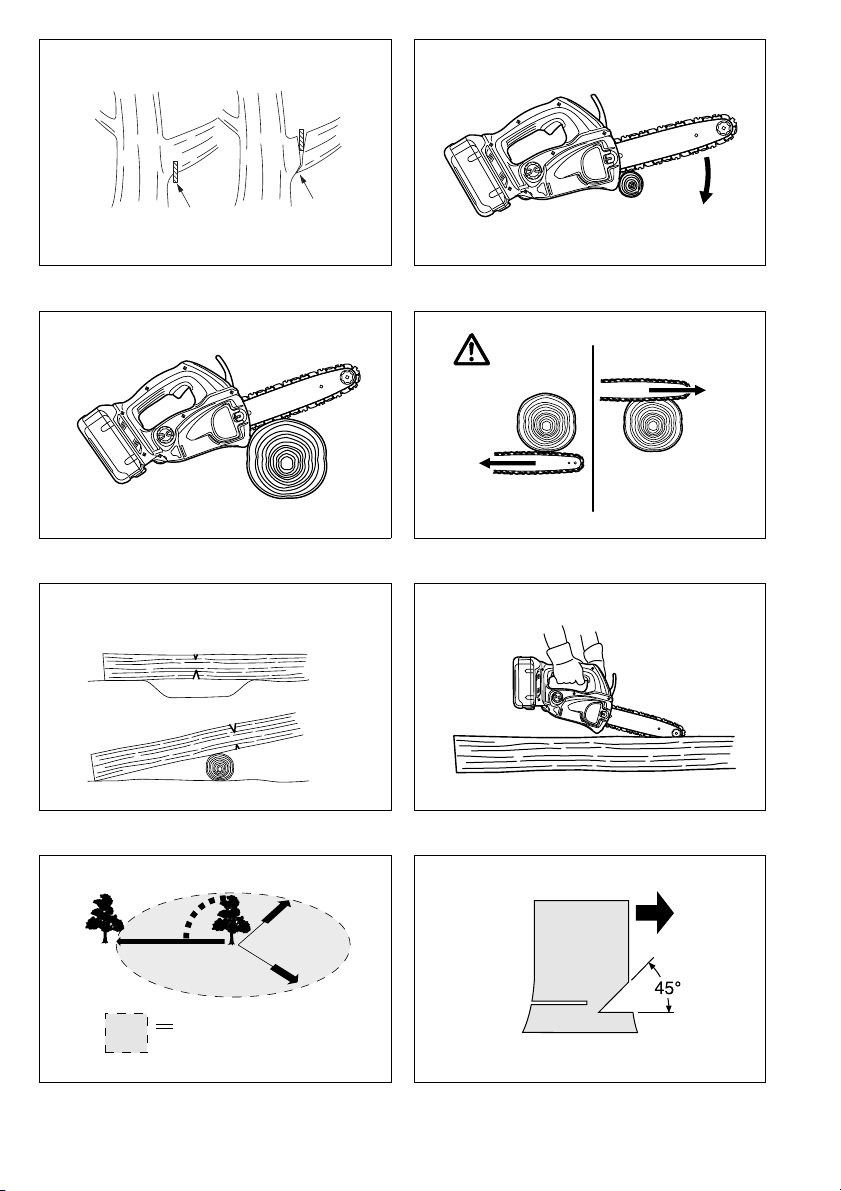
Felling
CAUTION:
• Felling work may only be performed by trained persons.
The work is hazardous.
Observe local regulations if you wish to fell a tree.
- Before starting felling work, ensure that: (Fig. 31)
(1) Only persons involved in the felling operation are in
the vicinity;
(2) Any person involved has an unhindered path of
retreat through a range of approximately 45° either
side of the felling axis. Consider the additional risk
of tripping over electrical cables;
(3) The base of the trunk is free of foreign objects,
roots and branches;
(4) No persons or objects are present over a distance
of 2 1/2 tree lengths in the direction in which the
tree will fall.
- Consider the following with respect to each tree:
• Direction of lean;
• Loose or dry branches;
• Height of the tree;
• Natural overhang;
• Whether or not the tree is rotten.
- Consider the wind speed and direction. Do not carry
out felling work if the wind is gusting strongly.
- Trimming of root swellings: Begin with the largest swellings. Make the vertical cut first, then the horizontal cut.
(Fig. 32)
- Cut a scarf: The scarf determines the direction in which
the tree will fall, and guides it. It is made on the side
towards which the tree is to fall. Cut the scarf as close
to the ground as possible. First make the horizontal cut
to a depth of 1/5 – 1/3 of the trunk diameter. Do not
make the scarf too large. Then make the diagonal cut.
- Cut any corrections to the scarf across its entire width.
- Make the back cut a little higher than the base cut of
the scarf. The back cut must be exactly horizontal.
Leave approximately 1/10 of the trunk diameter
between the back cut and the scarf.
The wood fibers in the uncut trunk portion act as a
hinge. Do not cut right through the fibers under any circumstances, as the tree will otherwise fall unchecked.
Insert wedges into the back cut in time. (Fig. 33)
- Only plastic or aluminum wedges may be used to keep
the back cut open. The use of iron wedges is prohibited.
- Stand to the side of the falling tree. Keep an area clear
to the rear of the falling tree up to an angle of 45° either
side of the tree axis (refer to the “felling area” figure
(Fig. 31)). Pay attention to falling branches.
- An escape path should be planned and cleared as necessary before cuts are started. The escape path should
extend back and diagonally to the rear of the expected
line of fall as illustrated in figure. (Fig. 34)
21

Carrying tool (Fig. 35)
Always remove the battery cartridge from the tool and
overlap the guide bar with the scabbard before carrying
the tool. Also cover the battery cartridge with the battery
cover.
MAINTENANCE
CAUTION:
• Always be sure that the tool is switched off and the battery cartridge is removed before attempting to perform
inspection or maintenance.
• Always wear gloves when performing any inspection or
maintenance.
• Never use gasoline, benzine, thinner, alcohol or the
like. Discoloration, deformation or cracks may result.
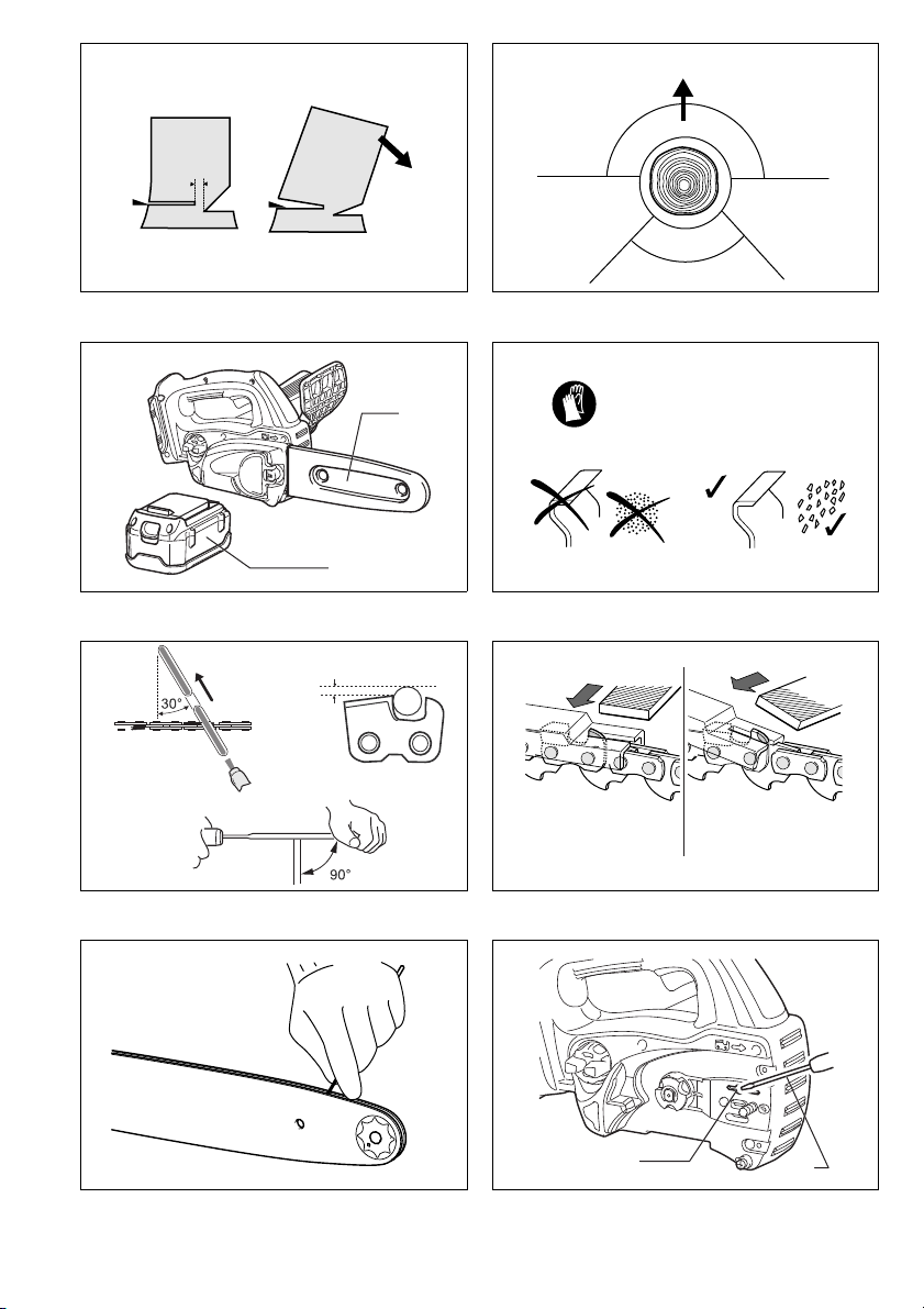
Sharpening the saw chain
CAUTION:
• Always remove the battery cartridge and wear safety
gloves when performing work on the saw chain.
Sharpen the saw chain when:
- Mealy sawdust is produced when damp wood is cut;
- The chain penetrates the wood with difficulty, even
when heavy pressure is applied;
- The cutting edge is obviously damaged;
- The saw pulls to the left or right in the wood. The reason for this behaviour is uneven sharpening of the saw
chain, or damage to one side only. (Fig. 36)
Sharpen the saw chain frequently, but remove only a
little material each time.
Two or three strokes with a file are usually sufficient for
routine resharpening. When the saw chain has been
resharpened several times, have it sharpened in a
DOLMAR specialist repair shop.
File and file guiding
- Use a special round file (optional accessory) for saw
chains, with a diameter of 4 mm, to sharpen the chain.
Normal round files are not suitable.
- The file should only engage the material on the forward
stroke. Lift the file off the material on the return stroke.
- Sharpen the shortest cutter first. The length of this cutter is then the gauge dimension for all other cutters on
the saw chain.
- Guide the file as shown in the figure. (Fig. 37)
- The file can be guided more easily if a file holder
(accessory) is employed. The file holder has markings
for the correct sharpening angle of 30° (align the markings parallel to the saw chain) and limits the depth of
penetration (to 4/5 of the file diameter).
Guide the file as shown in the figure. (Fig. 38)
- After sharpening the chain, check the height of the
depth gauge using the chain gauge tool (optional
accessory).
- Remove any projecting material, however small, with a
special flat file (optional accessory).
- Round off the front of the depth gauge again.
- Wash away dust and particles from saw chain after
adjusting the height of depth gauge.
Cleaning guide bar (Fig. 39)
Chips and sawdust will build up in the guide bar groove,
clogging it and impairing oil flow. Always clean out the
chips and sawdust when sharpening or replacing the saw
chain.
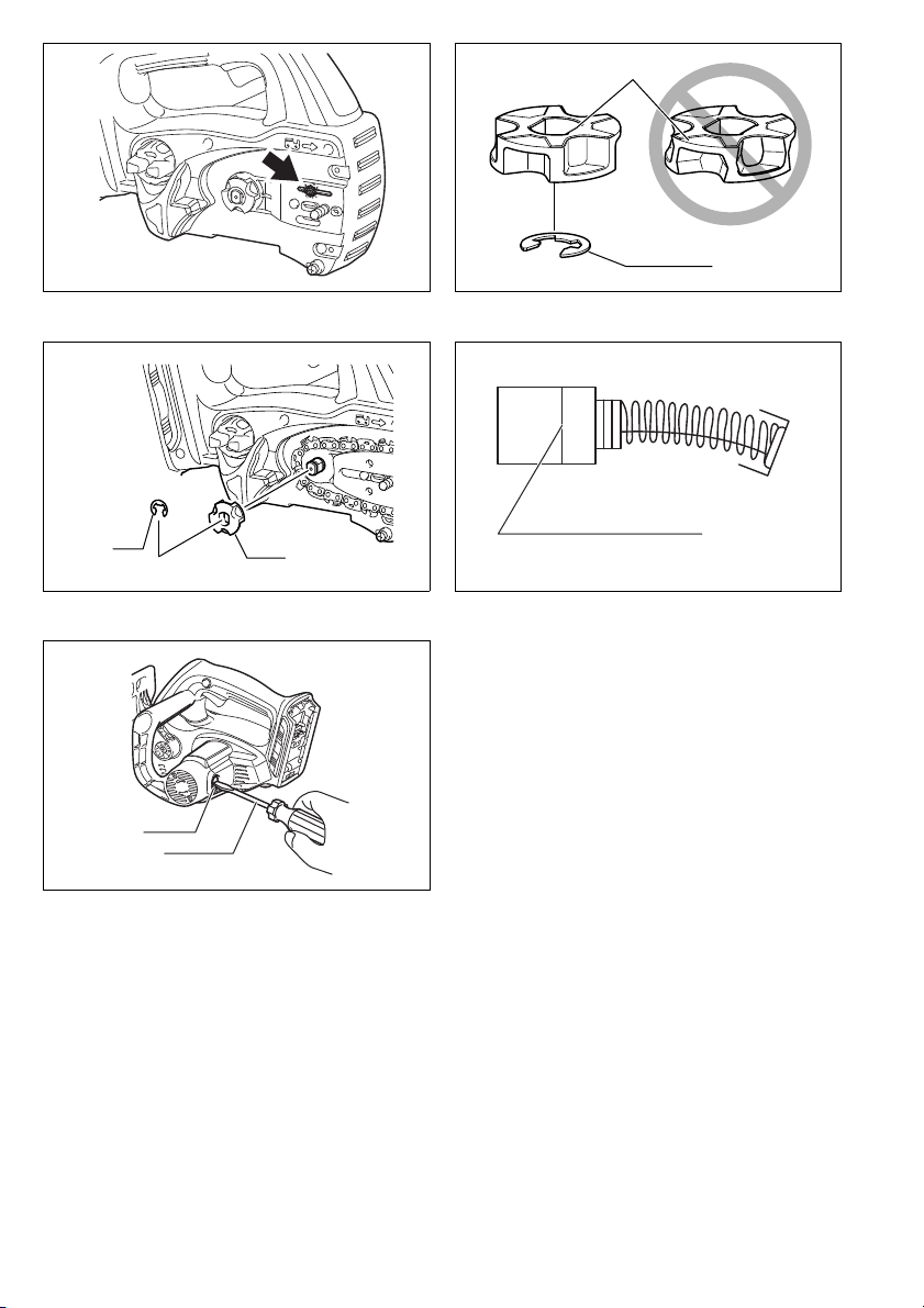
Cleaning the oil discharge hole
Small dust or particles may be built up in the oil discharge hole during operation.
Small dust or particles built up in the oil discharge hole
may impair the oil discharge flow and cause an insufficient lubrication on the whole saw chain.
When a poor chain oil delivery occurs at the top of guide
bar, clean the oil discharge hole as follows.
Remove the battery cartridge from the tool.
Remove the sprocket cover and saw chain from the tool.
(Refer to the section titled “Installing or removing saw
chain”.)
Remove the small dust or particles using a slotted bit
screwdriver with a slender shaft or the like. (Fig. 40)
Insert the battery cartridge into the tool.
Pull the switch trigger to flow built-up dust or particles off
the oil discharge hole by discharging chain oil. (Fig. 41)
Remove the battery cartridge from the tool.
Reinstall the sprocket cover and saw chain on the tool.
Replacing the sprocket (Fig. 42 & 43)
Before fitting a new saw chain, check the condition of the
sprocket.
CAUTION:
• A worn sprocket will damage a new saw chain. Have
the sprocket replaced in this case. The sprocket need
to be installed so that it always faces as shown in the
figure.
Always fit a new locking ring when replacing the
sprocket.
Replacing carbon brushes (Fig. 44 & 45)
Remove and check the carbon brushes regularly.
Replace when they wear down to the limit mark. Keep
the carbon brushes clean and free to slip in the holders.
Both carbon brushes should be replaced at the same
time. Use only identical carbon brushes.
Use a screwdriver to remove the brush holder caps. Take
out the worn carbon brushes, insert the new ones and
secure the brush holder caps.
Storing tool
Clean the tool before storing. Remove any chips and
sawdust from the tool after removing the sprocket cover.
After cleaning the tool, run it under no load to lubricate
the saw chain and guide bar.
Cover the guide bar with the scabbard.
Remove oil from the oil tank to empty it and place the
chain saw.
To maintain product SAFETY and RELIABILITY, repairs,
any other maintenance or adjustment should be performed by DOLMAR Authorized Service Centres, always
using Dolmar replacement parts.
22

OPTIONAL ACCESSORIES
CAUTION:
• These accessories or attachments are recommended
for use with your Dolmar tool specified in this manual.
The use of any other accessories or attachments might
present a risk of injury to persons. Only use accessory
or attachment for its stated purpose.
If you need any assistance for more details regarding
these accessories, ask your local Dolmar Service Center.
• Various type of Dolmar genuine batteries and chargers
• Saw chain
• Scabbard
• Guide bar complete
•File
• Tool bag
• Battery adapter
• Arm cord hook (to be used together with the battery
adapter)
NOTE:
• Some items in the list may be included in the tool package as standard accessories. They may differ from
country to country.
ENG102-3
Noise
The typical A-weighted noise level determined according
to EN60745:
Sound pressure level (L
Sound power level (L
Uncertainty (K): 3.0 dB (A)
Wear ear protection
Vibration
The vibration total value (tri-axial vector sum) determined
according to EN60745:
Work mode: cutting wood
Vibration emission (a
Uncertainty (K): 1.6 m/s
• The declared vibration emission value has been measured in accordance with the standard test method and
may be used for comparing one tool with another.
• The declared vibration emission value may also be
used in a preliminary assessment of exposure.
WARNING:
• The vibration emission during actual use of the power
tool can differ from the declared emission value
depending on the ways in which the tool is used.
• Be sure to identify safety measures to protect the operator that are based on an estimation of exposure in the
actual conditions of use (taking account of all parts of
the operating cycle such as the times when the tool is
switched off and when it is running idle in addition to
the trigger time).
): 87.3 dB (A)
pA
): 95.3 dB (A)
WA
): 7.0 m/s
h
2
ENG221-2
2
ENG901-1
ENH031-2
For European countries only
EC Declaration of Conformity
The undersigned, Tamiro Kishima and Rainer
Bergfeld, as authorized by Dolmar GmbH, declare
that the DOLMAR machine(s):
Designation of Machine: Cordless Chain Saw
Model No./ Type: AS-3625, AS-3626
Specifications: see “SPECIFICATIONS” table.
are of series production and
Conforms to the following European Directives:
2000/14/EC, 2006/42/EC
And are manufactured in accordance with the following
standards or standardised documents:
EN60745
The EC-Type Examination Certificate No. 3400780.02CE
(AS-3625), No. 3400780.04CE (AS-3626)
The EC-Type Examination per 2006/42/EC was performed by:
KEMA Quality GmbH
Enderstraße 92b
01277 Dresden
Germany
Identification No. 2140
The technical documentation is on file at:
Dolmar GmbH,
Jenfelder Straße 38, Abteilung FZ,
D-22045 Hamburg
The conformity assessment procedure required by Directive 2000/14/EC was in Accordance with annex V.
Measured Sound Power Level: 95.2 dB (A)
Guaranteed Sound Power Level: 98.0 dB (A)
19.11.2010
Tamiro Kishima
Managing Director
Rainer Bergfeld
Managing Director
23

FRANÇAIS (Instructions originales)
Descriptif
1 Partie rouge
2 Bouton
3 Batterie
4 Bouton de sécurité
5 Gâchette
6 Protège-main avant
7 Verrouiller
8 Déverrouiller
9 Vis de réglage
10 Mousqueton (point de fixation
de la corde)
11 Témoins
12 Bouton CHECK
13 Faire glisser légèrement
14 Placer à la verticale
15 Enfoncer
16 Desserrer
17 Couvre-pignon
18 Bague de réglage
19 Pignon
SPÉCIFICATIONS
Modèle AS-3625 AS-3626
Vitesse de chaîne par minute 8,3 m/s (500 m/min) 8,3 m/s (500 m/min)
Longueur du guide de chaîne 250 mm 250 mm
Type de guide de chaîne
Type 91VG 25AP 91VG 25AP
Chaîne
Nombre de dents 6 9 6 9
Longueur totale 576 mm 589 mm 577 mm 590 mm
Poids net 4,5 kg 4,5 kg
Tension nominale 36 V CC 36 V CC
• Poids, avec la batterie, conformément à la procédure
EPTA-01/2003
Utilisations
L’outil est conçu pour le tronçonnage du bois d’œuvre et
des rondins.
Consignes de sécurité générales pour outils électriques
MISE EN GARDE Veuillez lire toutes les mises en
garde et toutes les instructions. Il y a risque de choc
électrique, d’incendie et/ou de blessure grave si les
mises en garde et les instructions ne sont pas
respectées.
Conservez toutes les mises en garde et instructions
pour référence ultérieure.
Pas 3/8” 1/4” 3/8” 1/4”
Nombre de maillons
d’entraînement
20 Broche de réglage
21 Petit orifice
22 Serrer
23 Levier
24 Bas
25 Haut
26 Guide de chaîne
27 Chaîne
28 Adaptateur
29 Crochet
30 Outil
31 Ceinture
32 Bande du crochet-brassard
33 Support
34 Cordon prolongateur (adapta-
teur de batterie)
35 Adaptateur (adaptateur de bat-
terie)
36 Bouchon du réservoir d’huile
37 Ouverture du réservoir d’huile
Guide à pignon
de renvoi
40 60 40 60
ENE031-1
GEA010-1
Barre de
cisellement
CONSIGNES DE SÉCURITÉ POUR
TRONÇONNEUSE SANS FIL :
1. Gardez toute partie du corps à l’écart de la
chaîne pendant l’utilisation de la tronçonneuse.
Avant de faire démarrer la tronçonneuse, assurez-vous que la chaîne n’entre en contact avec
rien. Tout moment d’inattention pendant l’utilisation
d’une tronçonneuse comporte un risque de contact
entre la chaîne et vos vêtements ou votre corps.
2. Tenez toujours la tronçonneuse fermement avec
la main droite sur la poignée arrière et la main
gauche sur la poignée avant. N’inversez jamais les
mains pour tenir la tronçonneuse car il y a risque de
blessure.
38 Fenêtre d’inspection du
réservoir d’huile (pour remplir le
réservoir d’huile)
39 Fenêtre d’inspection du
réservoir d’huile
40 Guide inférieur
41 Zone de chute
42 Sens de la chute
43 Zone de danger
44 Voie de retraite
45 Fourreau (cache de chaîne)
46 Limage vers l’avant
47 1/5 du diamètre de lime
48 Poussières ou particules
49 Tournevis à tête fendue
50 Bague de blocage
51 Trait de limite d’usure
52 Bouchons de porte-charbon
53 Tournevis
Guide à pignon
de renvoi
Barre de
cisellement
GEB071-5
24
3. Tenez l’outil électrique uniquement par ses surfaces de poigne isolées, car la chaîne peut entrer
en contact avec des câbles cachés. Le contact de
la chaîne avec un câble sous tension peut mettre les
parties métalliques dénudées de l’outil sous tension
et exposer l’utilisateur à un choc électrique.
4. Portez des lunettes de sécurité et une protection
d’oreilles. Il est recommandé de porter des dispositifs de protection supplémentaires pour la
tête, les mains, les jambes et les pieds. Le port de
vêtements de protection adéquats réduit le risque de
blessure causée par les débris éjectés ou par le
contact avec la chaîne.
5. Avant de commencer le travail, assurez-vous que la
tronçonneuse est en bon état et conforme aux
réglementations de sécurité. Vérifiez tout
particulièrement les points suivants :
• Le frein de chaîne fonctionne bien.
• Le frein de désamorçage fonctionne bien.
• Le guide et le couvre-pignon sont posés
correctement.
• La chaîne est bien aiguisée et bien tendue,
conformément aux réglementations.
6. N’utilisez pas la tronçonneuse en grimpant sur
un arbre. Il y a risque de blessure si la tronçon-
neuse est utilisée sur un arbre.
7. Assurez-vous toujours d’être en bonne position
d’équilibre et d’utiliser la tronçonneuse sur une
surface stable, sûre et plane. Vous risquez de per-
dre l’équilibre ou de perdre la maîtrise de la tronçonneuse si vous travaillez sur une surface glissante ou
instable comme une échelle.
8. Lorsque vous coupez une branche tendue, prenez garde au retour de la branche. Lorsque la ten-
sion exercée sur les fibres de la branche tendue est
libérée, elle risque de frapper l’utilisateur et/ou de
provoquer une perte de maîtrise de la tronçonneuse.
9. Faites preuve d’une grande prudence lorsque
vous coupez des broussailles ou des jeunes
arbres. Des fines pièces de bois, en se coinçant
dans la chaîne, peuvent être projetées vers vous ou
exercer une traction vous mettant hors d’équilibre.
10. Pour transporter la tronçonneuse, coupez le
contact, saisissez-la par la poignée avant et gardez-la éloignée du corps. Avant de transporter
ou de ranger la tronçonneuse, installez toujours
le protecteur du guide de chaîne. Une manipula-
tion adéquate de la tronçonneuse réduit le risque de
contact avec la chaîne en mouvement.
11. Suivez les instructions de lubrification, de
réglage de la tension de la chaîne et de changement des accessoires. Une chaîne mal tendue ou
mal lubrifiée peut se casser ou augmenter les risques de choc en retour.
12. Maintenez les poignées sèches, propres et
exemptes d’huile et de graisse. Les poignées
graisseuses ou huileuses sont glissantes et peuvent
causer une perte de maîtrise.
13. Coupez uniquement dans le bois. N’utilisez pas
la tronçonneuse pour des travaux autres que
ceux pour lesquels elle a été conçue. Par exemple, ne l’utilisez pas pour couper le plastique, les
matériaux de maçonnerie et les matériaux de
construction autres que le bois. L’utilisation de la
tronçonneuse pour effectuer des travaux autres que
ceux pour lesquels elle a été conçue comporte un
risque de danger.
14. Causes de choc en retour et mesures préventives à prendre :
Il y a risque de choc en retour lorsque le nez ou le
bout du guide de chaîne touche un objet, ou lorsque
le bois se referme et coince la chaîne dans sa ligne
de coupe.
Le contact du bout, dans certains cas, peut entraîner une réaction instantanée en sens inverse, projetant le guide de chaîne vers le haut et vers
l’utilisateur.
Le guide de chaîne risque d’être projeté vers l’utilisateur si la chaîne se coince le long de la partie
supérieure du guide de chaîne.
L’une ou l’autre de ces réactions peut entraîner une
perte de maîtrise de la scie et causer une grave
blessure. Ne vous fiez pas uniquement aux dispositifs de sécurité intégrés à la scie. En tant qu’utilisateur de la tronçonneuse, vous devez prendre des
mesures pour écarter les risques d’accident ou de
blessure pendant le travail de coupe.
Le choc en retour est le résultat d’une mauvaise utilisation et/ou de procédures ou conditions inadéquates de travail. Il peut être évité en prenant les
mesures appropriées, tel qu’indiqué ci-dessous :
- Maintenez une prise ferme, avec les pouces et les
doigts encerclant les poignées de la tronçonneuse, tenez la tronçonneuse à deux mains et placez le corps et les bras dans une position vous
permettant de résister aux chocs en retour. Les
forces de choc en retour peuvent être contrôlées
par l’utilisateur s’il prend les précautions nécessaires. Ne lâchez pas la tronçonneuse.
- Ne vous penchez pas trop en avant, et ne cou-
pez pas plus haut qu’à la hauteur des épaules.
Cela aide à éviter le contact involontaire du bout et
permet de mieux maîtriser la tronçonneuse dans
les situations imprévues.
- Utilisez exclusivement les guides et chaînes
spécifié(e)s par le fabricant. Un remplacement
incorrect du guide ou de la chaîne peut causer le
bris de la chaîne et/ou un choc en retour.
- Suivez les instructions du fabricant concer-
nant l’affûtage et l’entretien de la chaîne. Le risque de choc en retour augmente si l’on abaisse la
jauge de profondeur.
15. Ne faites pas démarrer la tronçonneuse sans
avoir retiré le cache de chaîne. Si vous faites
démarrer la tronçonneuse sans avoir retiré le cache
de chaîne, celui-ci risquera d’être éjecté vers l’avant,
ce qui comporte un risque de blessure et peut
endommager les objets autour de l’utilisateur.
CONSERVEZ CES INSTRUCTIONS.
25

AVERTISSEMENT :
NE vous laissez PAS tromper (au fil d’une utilisation
répétée) par un sentiment d’aisance et de familiarité
avec le produit, en négligeant le respect rigoureux
des consignes de sécurité qui accompagnent le produit en question. La MAUVAISE UTILISATION de
l’outil ou l’ignorance des consignes de sécurité indiquées dans ce manuel d’instructions peut entraîner
une blessure grave.
ENC007-6
PRÉCAUTIONS IMPORTANTES
POUR LA BATTERIE
1. Avant d’utiliser la batterie, lisez toutes les ins-
tructions et précautions relatives (1) au chargeur
de batterie, (2) à la batterie, et (3) à l’outil utilisant la batterie.
2. Ne démontez pas la batterie.
3. Cessez immédiatement l’utilisation si le temps
de fonctionnement devient excessivement court.
Il y a risque de surchauffe, de brûlures, voire
d’explosion.
4. Si l’électrolyte pénètre dans vos yeux, rincez-les
à l’eau claire et consultez immédiatement un
médecin. Il y a risque de perte de la vue.
5. Ne court-circuitez pas la batterie :
(1) Ne touchez les bornes avec aucun matériau
conducteur.
(2) Évitez de ranger la batterie dans un conte-
neur avec d’autres objets métalliques, par
exemple des clous, des pièces de monnaie,
etc.
(3) N’exposez pas la batterie à l’eau ou à la pluie.
Un court-circuit de la batterie pourrait provoquer
un fort courant, une surchauffe, parfois des brûlures et même une panne.
6. Ne rangez pas l’outil ou la batterie dans des
endroits où la température risque d’atteindre ou
de dépasser 50°C.
7. Ne jetez pas la batterie au feu même si elle est
sérieusement endommagée ou complètement
épuisée. La batterie peut exploser au contact du
feu.
8. Prenez garde d’échapper ou de heurter la batte-
rie.
9. N’utilisez pas une batterie qui a été échappée ou
heurtée.
CONSERVEZ CES INSTRUCTIONS.
Conseils pour assurer la durée de vie optimale de
la batterie
1. Rechargez la batterie avant qu’elle ne soit com-
plètement déchargée.
Arrêtez toujours l’outil et rechargez la batterie
quand vous remarquez que la puissance de
l’outil diminue.
2. Ne rechargez jamais une batterie complètement
chargée. La surcharge réduit la durée de service
de la batterie.
3. Chargez la batterie alors que la température de
la pièce se trouve entre 10°C et 40°C. Avant de
charger une batterie chaude, laissez-la refroidir.
DESCRIPTION DU FONCTIONNEMENT
ATTENTION :
• Assurez-vous toujours que l’outil est hors tension et
que sa batterie est retirée avant de l’ajuster ou de vérifier son fonctionnement.
Installation et retrait de la batterie (Fig. 1)
ATTENTION :
• Tenez fermement l’outil et la batterie lorsque vous
insérez ou retirez la batterie. Si vous ne tenez pas
fermement l’outil et la batterie, vous risquerez de les
endommager et de vous blesser en les échappant.
• Mettez toujours l’outil hors tension avant d’installer ou
de retirer la batterie.
• Pour retirer la batterie, sortez-la de l’outil tout en faisant
glisser le bouton à l’avant de la batterie.
• Pour insérer la batterie, alignez la languette de la batterie avec la rainure située dans le carter, puis faites-la
glisser en place. Insérez-la toujours à fond, jusqu’à ce
qu’un léger déclic se fasse entendre. Si vous pouvez
voir la partie rouge du côté supérieur du bouton, la batterie n’est pas complètement verrouillée. Insérez-la
entièrement, jusqu’à ce que la partie rouge ne soit plus
visible. Sinon, elle pourrait tomber accidentellement de
l’outil, au risque de vous blesser ou de blesser
quelqu’un se trouvant près de vous.
• N’insérez pas la batterie de force. Si elle ne rentre pas
facilement, c’est que vous ne l’insérez pas correctement.
Interrupteur (Fig. 2)
ATTENTION :
• Avant d’insérer la batterie dans l’outil, vérifiez toujours
que la gâchette fonctionne correctement et qu’elle
revient sur la position “OFF” quand vous la relâchez.
Pour éviter tout déclenchement accidentel de la
gâchette, un bouton de sécurité a été prévu.
Pour démarrer l’outil, appuyez sur le bouton de sécurité et
tirez sur la gâchette. Pour l’arrêter, relâchez la gâchette.
Vérification du frein de chaîne (Fig. 3)
NOTE :
• Si la tronçonneuse ne démarre pas, vous devez libérer
le frein de chaîne. Tirez fermement le protège-main
avant vers l’arrière, jusqu’à ce que vous sentiez qu’il
s’engage.
Tenez la tronçonneuse à deux mains lorsque vous
mettez le contact.
Tenez la poignée supérieure avec la main droite, et la
poignée avant avec la main gauche. Le guide et la
chaîne ne doivent entrer en contact avec aucun objet.
Appuyez d’abord sur le bouton de sécurité, puis sur la
gâchette.
La chaîne démarre immédiatement.
Poussez le protège-main avant vers l’avant avec le dos
de la main. La chaîne doit s’immobiliser immédiatement.
ATTENTION :
• Si la chaîne ne s’arrête pas immédiatement lors de ce
test, la chaîne ne doit être utilisée en aucune
circonstance. Contactez un atelier de réparation
spécialisé en outils DOLMAR.
Vérification du frein de désamorçage
Faites démarrer la tronçonneuse.
Libérez complètement la gâchette. La chaîne doit
s’arrêter en moins d’une seconde.
26
ATTENTION :
Allumé
Arrêt
Clignotant
E
F
• Si la chaîne ne s’arrête pas en moins d’une seconde
lors de ce test, la tronçonneuse ne doit pas être
utilisée. Contactez un atelier de réparation spécialisé
en outils DOLMAR.
Réglage de la lubrification de la chaîne (Fig. 4)
Vous pouvez régler le taux d’alimentation de la pompe à
huile à l’aide de la vis de réglage. La quantité d’huile peut
être réglée à l’aide de la clé universelle.
Mousqueton (point de fixation de la corde) (Fig. 5)
Le mousqueton (point de fixation de la corde) sert à
suspendre l’outil. Avant d’utiliser le mousqueton, tirez
dessus pour le dégager et attachez-y une corde.
Circuit de protection de la batterie
L’outil est doté d’un circuit de protection qui coupe
automatiquement l’alimentation pour assurer une longue
durée de service.
Il se peut que l’outil s’arrête en cours d’utilisation si l’outil
et/ou la batterie se trouvent dans la situation suivante.
Cela est dû à l’activation du circuit de protection et
n’indique aucun problème de fonctionnement de l’outil.
• Lorsque l’outil est surchargé :
Libérez alors la gâchette, éliminez la cause de la
surcharge puis appuyez de nouveau sur la gâchette
pour redémarrer. Si l’outil ne fonctionne toujours pas
sur pression de la gâchette, cela signifie que l’arrêt
automatique de la batterie est encore activé.
Chargez la batterie avant l’utilisation.
• Lorsque la charge restante de la batterie est faible :
Rechargez la batterie.
Témoin de capacité restante de la batterie
(uniquement pour les modèles dotés d’une
batterie AP-3622)
La batterie AP-3622 est dotée d’un témoin de capacité
restante. (Fig. 6)
Appuyez sur le bouton CHECK pour afficher la capacité
restante de la batterie. Le témoin s’allume alors pendant
trois secondes environ.
Témoins
Capacité restante
70% à 100%
45 % à 70 %
20% à 45%
0 % à 20 %
Chargez la batterie.
Il y a peut-être un
dysfonctionnement de la
batterie.
• Lorsque seul le témoin le plus bas (à côté de l’“E”)
clignote, ou lorsque aucun des témoins ne s’allume, la
capacité de la batterie est épuisée et l’outil ne peut plus
fonctionner. Le cas échéant, chargez la batterie ou
remplacez-la par une batterie complètement chargée.
• Si au moins deux témoins ne s’allument pas même
après la charge, cela signifie que la batterie a atteint la
fin de sa durée de service.
• Si les deux témoins supérieurs et les deux témoins
inférieurs s’allument alternativement, il se peut que la
batterie ait un dysfonctionnement. Contactez votre
centre de service après-vente agréé DOLMAR.
NOTE :
• Pendant ou juste après l’utilisation de l’outil, la capacité
restante indiquée peut être inférieure au véritable
niveau de capacité.
• Suivant les conditions d’utilisation et la température
ambiante, il se peut que la capacité restante indiquée
par le témoin soit légèrement différente de la charge
réelle.
ASSEMLAGE
ATTENTION :
• Assurez-vous toujours que l’outil est hors tension et
que sa batterie est retirée avant d’effectuer tout travail
dessus.
Installation ou retrait de la chaîne
ATTENTION :
• Assurez-vous toujours que l’outil est hors tension et
que la batterie est retirée avant d’installer ou de retirer
la chaîne de scie.
• Portez toujours des gants pour installer ou retirer la
chaîne de scie.
1. Pour retirer la tronçonneuse, faites glisser
légèrement le levier dans le sens de la flèche pour
qu’il puisse être libéré de la position de verrouillage,
puis placez-le à la verticale tel qu’illustré. (Fig. 7)
2. Appuyez sur le levier et, tout en le maintenant
enfoncé, tournez-le dans le sens contraire des
aiguilles d’une montre pour desserrer l’écrou jusqu’à
ce que le couvre-pignon se détache. (La pression
sur le levier le fait pénétrer dans l’écrou.) (Fig. 8)
3. Tournez la bague de réglage dans le sens contraire
des aiguilles d’une montre pour réduire la tension de
la chaîne.
4. Retirez le couvre-pignon.
5. Retirez la chaîne et le guide de chaîne de la
tronçonneuse.
6. Pour installer la chaîne, placez une de ses
extrémités sur le dessus du guide de chaîne, et
l’autre extrémité autour du pignon. (Fig. 9)
Posez alors la chaîne tel qu’illustré, car elle tourne dans
le sens de la flèche.
7. Laissez reposer le guide de chaîne dans cette
position sur la tronçonneuse.
8. Tournez la bague de réglage dans le sens contraire
des aiguilles d’une montre pour faire glisser la
broche de réglage dans le sens de la flèche.
(Fig. 10)
9. Placez le couvre-pignon sur la tronçonneuse de
sorte que la broche de réglage se trouve dans un
petit orifice du guide de chaîne. (Fig. 11)
10. Appuyez sur le levier et, tout en le maintenant
enfoncé, tournez-le complètement dans le sens des
aiguilles d’une montre pour serrer l’écrou. Faites-le
ensuite tourner d’un quart de tour dans le sens
contraire des aiguilles d’une montre pour desserrer
légèrement l’écrou. (Fig. 12)
27

Réglage de la tension de la chaîne
La chaîne peut se détendre au bout de plusieurs heures
d’utilisation. Vérifiez de temps à autre la tension de la
chaîne avant l’utilisation. (Fig. 13)
Redressez le levier.
Enfoncez le levier. Avec le levier enfoncé, faites-le
tourner d’un quart de tour dans le sens contraire des
aiguilles d’une montre pour desserrer légèrement l’écrou.
(La pression sur le levier le fait pénétrer dans l’écrou.)
(Fig. 14)
Tournez la bague de réglage pour ajuster la tension de la
chaîne. Saisissez la chaîne au milieu du guide de chaîne
et soulevez-la. L’espace libre entre le guide de chaîne et
l’éclisse extérieure de la chaîne doit être d’environ
2 à 4 mm. Si l’espace libre n’est pas d’environ 2 à 4 mm,
tournez légèrement la bague de réglage qui retient le
guide de chaîne. Effectuez alors le réglage avec le bout
du guide de chaîne pointant légèrement vers le haut.
(Fig. 15)
Avec le levier enfoncé, tournez-le complètement dans le
sens des aiguilles d’une montre pour serrer l’écrou
fermement. (Fig. 16)
Remettez le levier sur sa position initiale. (Fig. 17)
ATTENTION :
• Si la chaîne est trop tendue, il y a risque de bris de la
chaîne, d’usure du guide de chaîne et de bris de la
bague de réglage.
• L’installation et le retrait de la chaîne doivent être effectués dans un emplacement propre, sans sciure de bois,
etc.
Adaptateur de batterie (en accessoire)
(Fig. 18 et 19)
ATTENTION :
• Avant d’utiliser l’adaptateur de batterie, veuillez lire toutes les instructions de l’outil alimenté par batterie.
• Avant de charger la batterie, retirez-la de l’adaptateur
de batterie. Il ne faut pas charger la batterie pendant
l’utilisation de l’adaptateur de batterie.
Pose ou retrait de l’adaptateur de batterie
• Mettez toujours l’outil hors tension avant d’insérer ou
de retirer l’adaptateur de batterie.
• Pour retirer l’adaptateur de batterie, tirez dessus tout
en faisant glisser son bouton.
• Pour insérer l’adaptateur de batterie, alignez sa languette sur la rainure à l’intérieur du carter et faites-le
glisser en place. Insérez-le toujours à fond, jusqu’à ce
qu’il se mette en place avec un léger déclic. Si vous
pouvez voir la partie rouge du côté supérieur du bouton, l’adaptateur n’est pas complètement verrouillé.
Insérez-le complètement, jusqu’à ce que la partie
rouge ne soit plus visible. Sinon, il pourrait tomber accidentellement de l’outil, au risque de vous blesser ou de
blesser quelqu’un se trouvant près de vous.
• N’insérez pas l’adaptateur de batterie de force. S’il ne
rentre pas facilement, c’est que vous ne l’insérez pas
correctement.
• Pour retirer la batterie de l’adaptateur ou pour l’y insérer, procédez de la même façon que pour la retirer de
l’outil ou pour l’y insérer.
• Abaissez complètement le crochet lorsque vous accrochez l’adaptateur de batterie à un ceinturon ou à un
objet similaire.
Crochet-brassard (en accessoire) (Fig. 20)
ATTENTION :
• Ne fixez pas le support du crochet-brassard à autre
chose que le cordon prolongateur. Sinon, il y a risque
d’accident ou de blessure.
L’utilisation du crochet-brassard réduit les risques de
sectionnement inattendu du cordon prolongateur lorsque
ce dernier pend librement.
Fixez fermement la bande du crochet-brassard autour de
votre bras, et faites passer le cordon prolongateur à travers le support. La longueur de la bande du crochetbrassard est réglable.
NOTE :
• Ne faites pas passer le cordon prolongateur à travers la
bande.
• Ne forcez pas l’ouverture du support. Sinon, vous risquez de le déformer et de l’abîmer.
OPÉRATION
Lubrification (Fig. 21)
La chaîne se lubrifie automatiquement pendant l’utilisation de l’outil.
Vérifiez la quantité d’huile restante par la fenêtre d’inspection du réservoir d’huile.
Pour remplir le réservoir, retirez le bouchon posé sur
l’ouverture du réservoir d’huile. La capacité du réservoir
d’huile est de 85 ml.
Une fois le réservoir rempli, n’oubliez pas de visser le
bouchon du réservoir d’huile sur la tronçonneuse.
ATTENTION :
• La première fois que vous faites le plein d’huile sur la
tronçonneuse, ou lorsque vous refaites le plein après
avoir complètement vidé le réservoir d’huile, ajoutez de
l’huile jusqu’au bord inférieur du goulot de remplissage.
Autrement l’alimentation en huile risque d’être affectée.
• Pour huiler la chaîne, utilisez exclusivement de l’huile à
chaîne Dolmar ou une huile similaire disponible en
magasin.
• N’utilisez jamais d’huile contenant des poussières ou
particules, ni de l’huile volatile.
• Pour élaguer les arbres, utilisez une huile végétale.
L’huile minérale risquerait d’endommager les arbres.
• Ne forcez jamais la tronçonneuse lorsque vous élaguez
des arbres.
• Avant de tronçonner, assurez-vous que le bouchon du
réservoir d’huile est bien vissé en place.
Gardez la tronçonneuse à l’écart de l’arbre. Démarrez-la
et attendez que la chaîne soit bien lubrifiée.
Avant de mettre le contact, mettez le guide inférieur en
contact avec la branche à couper. Le guide de chaîne risque de trembler et vous risquez de vous blesser si vous
procédez à la coupe sans mettre le guide inférieur en
contact avec la branche.
Déplacez simplement la tronçonneuse vers le bas pour
couper la branche. (Fig. 22)
UTILISATION DE LA TRONÇONNEUSE
Un utilisateur sans expérience doit effectuer, en guise
d’entraînement minimum, des coupes de rondins sur un
chevalet ou autre appui.
Elagage des arbres
ATTENTION :
• Eloignez toutes les parties du corps de la chaîne lorsque le moteur fonctionne.
28
 Loading...