

Models No.
Description
PRODUCT
T
ECHNICAL INFORMATION
CONCEPT AND MAIN APPLICATIONS
P 1/20
AR410HR
Pneumatic Auto Feed Coil Screwdriver
Model AR410HR is a pneumatic screwdriver powered by high pressure air.
Drives coil type collated drywall screws exactly to depth and fastens plasterboard
securely to wood/metal drywall stud.
Its main benefits are:
Compact body for easy handling and high maneuverability
High power allowing to fasten plasterboard securely to metal stud
of even 0.8mm thick steel plate without unseated screw
Optimum for operation in job sites among residential area
thanks to low-noise air exhaust
Rigid contact arm enabling to make fine finish constantly
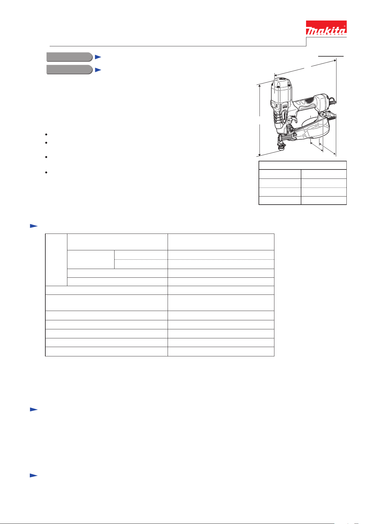
Dimensions: mm
Width 2 (W2)
Height (H)
Length (L) 296
142Width 1 (W1)
Width 1: with Hook
Width 2: without Hook
116
305
W2
W1
Specification
Standard equipment
Optional accessories
Note: The standard equipment for the tool shown above may vary by country.
Hook ................................................................. 1
Safety goggles ................................................... 1
Oil supply (containing 30ml of turbine oil) ...... 1
Hex wrench 4 ................................................... 1
Driver bit .......................................................... 1
Plastic carrying case ......................................... 1
Plastic sheet collated drywall screws (coil type)
[3.5mm shank diameter: 25, 28, 41mm; 3.8mm shank diameter: 25, 28, 32, 41mm]
Air hose
Air leak repair set
Screws per coil 100 screws
Net weight: kg
Magazine capacity
Screw
Operating air pressure: MPa
(kgf/cm2)
1.9
100 screws
1.76 - 2.26
(18 - 23)
25, 28, 32, 41
Plastic sheet collated drywall screws
(coil type)
Pressure regulator valve Yes
Length: mm
3.8 (Coarse thread)
3.5 (Fine thread)
Shank diameter:
mm
Wood backing
Metal backing
Screw type
L
H
*1: Screws can be driven one after the other continuously first by pulling Trigger then by
bumping Contact arm against workpiece with the Trigger being pulled.
*2: One screw is driven first by pushing Contact arm against workpiece, then by pulling
Trigger with the Contact arm kept pushed; screw cannot be driven when the steps are
reversed. Another one can be driven by releasing Trigger, then by repeating the steps;
however, cannot be driven if Trigger is not released before repetition of the steps.
Driving depth adjustment
Trigger lock-off function
Fire mechanism
Yes (by dial)
Yes
Bump-fire*1/ Sequential*2
P 2/20
Repair
[1] NECESSARY REPAIRING TOOLS
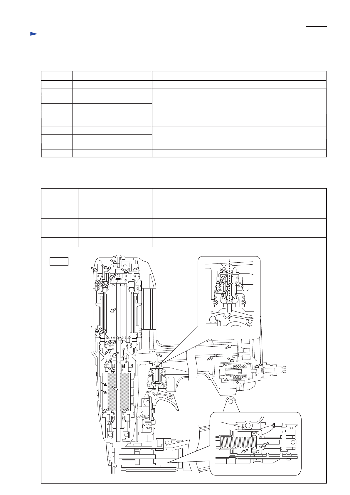
[2] LUBRICATIONS
Fig. 1
Code No. Description Use for
1R003 Retaining ring S pliers ST-2N Removing Pipe 13
1R027 Bearing setting pipe 18-10.2 Assembling Rotor
1R045 Gear extractor (large)
1R346 Center attachment for 1R045
Disassembling Rotor
1R229 1/4” Hex. shank bit for M5 Screwing/unscrewing M5 Hex socket head bolt
1R266 Spring pin extractor 2 Disassembling Adjuster complete and Adjuster shaft
1R273 Ring spring 26 setting tool B Assembling Air Motor section
1R291 Retaining ring S & R pliers Disassembling/assembling Retaining ring R-24 from/to Feed piston
1R267 Spring pin extractor 2.5
Disassembling Trigger and Idler
1R268 Spring pin extractor 3
Item No.
Apply ISOFLEX NB52 to the portions designated with the white arrow, and apply lubricant VG32 to the portions
designated with black arrow, to protect parts and product from unusual abrasion.
Description Portion to lubricate
CAUTION: Disconnect the air hose from the machine and then remove remaining screws for
safety before repair/ maintenance in accordance with the instruction manual!
Trigger valve section
Inlet section
Drive section
Nail drive section
Trigger valve section
Inlet section Plug, Inlet cap, etc.
Nail feed piston section Cup washer, O rings, etc.
O rings, Trigger valve case, Trigger stem, Pilot valve, etc.
Cylinder, O rings, Driver bit set, etc.
Air Motor (Apply lubricant “VG32” to the Drum portion of Air motor.)
Air motor
Nail feed piston section
P 3/20
Repair
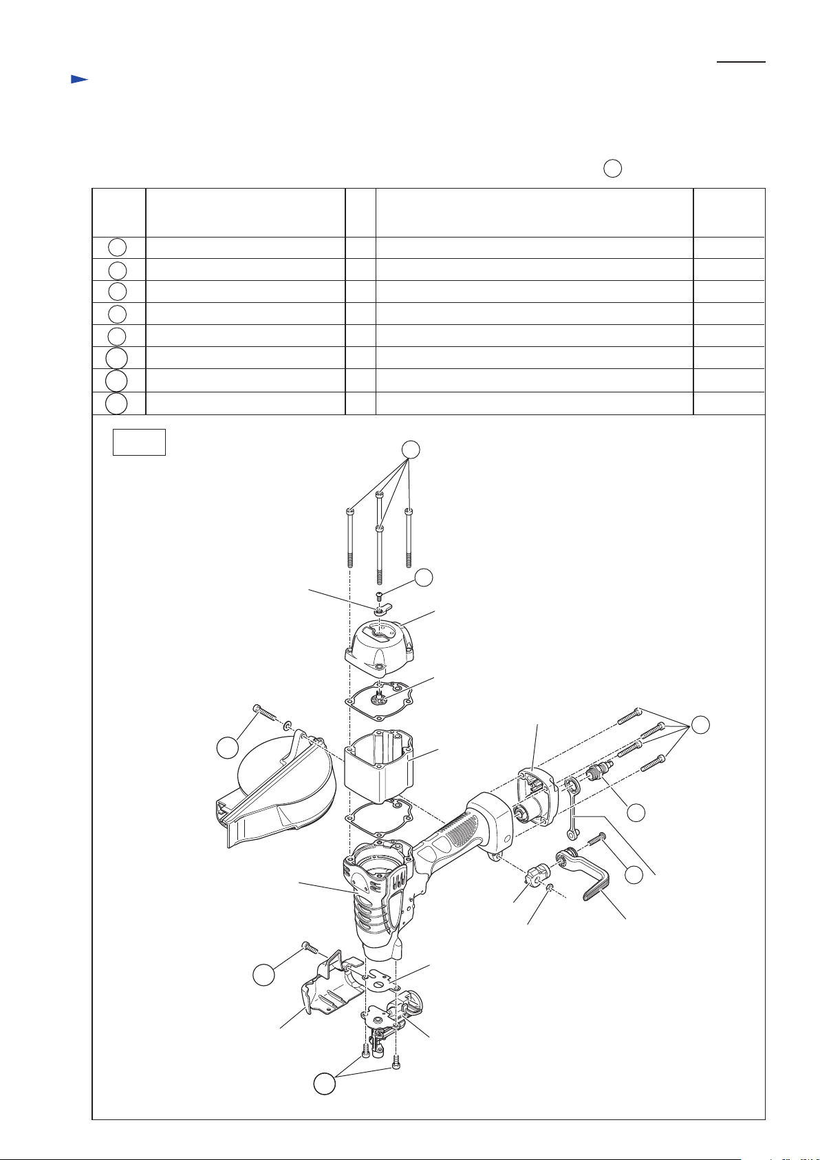
[3] DISASSEMBLY/ASSEMBLY
[3]-1. Fastening Torque for Bolts ans Scerws
Tighten the bolts and scerws to the required fastening torque.
* Apply a little amount of Loctite 242 or Three Bond 1321/1342 to the threaded portion of 77 Plug.
Fig. 2
Item No. Description
M5x80 Hex socket head bolt
M4x8 Hex socket button head bolt
M5x28 Hex socket head bolt
M5x30 Hex socket head bolt
Threaded portion of Plug
M5x22 Pan head screw
M5x16 Hex socket head bolt
M5x12 Hex socket head bolt
Fastening
torque
(N.m)
Q’ty
4
Used for
Fastening Top cap and Top cap spacer to Housing
1 Fastening Knob to Change valve
1 Fastening Magazine and Hook base to Housing
4 Fastening Inlet cap to Housing
1 Fastening Inlet and Inlet cap 9 to Housing
1 Fastening Hook to Hook base
1 Fastening Contact arm cover to Driver guide complete
2
8.0
2.5
2.5
8.0
7.0
2.5
2.5
8.0Fastening Driver guide complete to Housing
1
3
76
Contact arm cover
121
Driver guide complete
Driver guide gasket
Housing
M5 Hex nut
Change valve
Hook base
93
Hook
Cap 9
Inlet cap
Knob
Top cap
Top cap spacer
1
3
128
76
77
93
119
121
121
128
77
119
Compression
spring 4 (8 pcs)
P 4/20
Repair
[3] DISASSEMBLY/ASSEMBLY
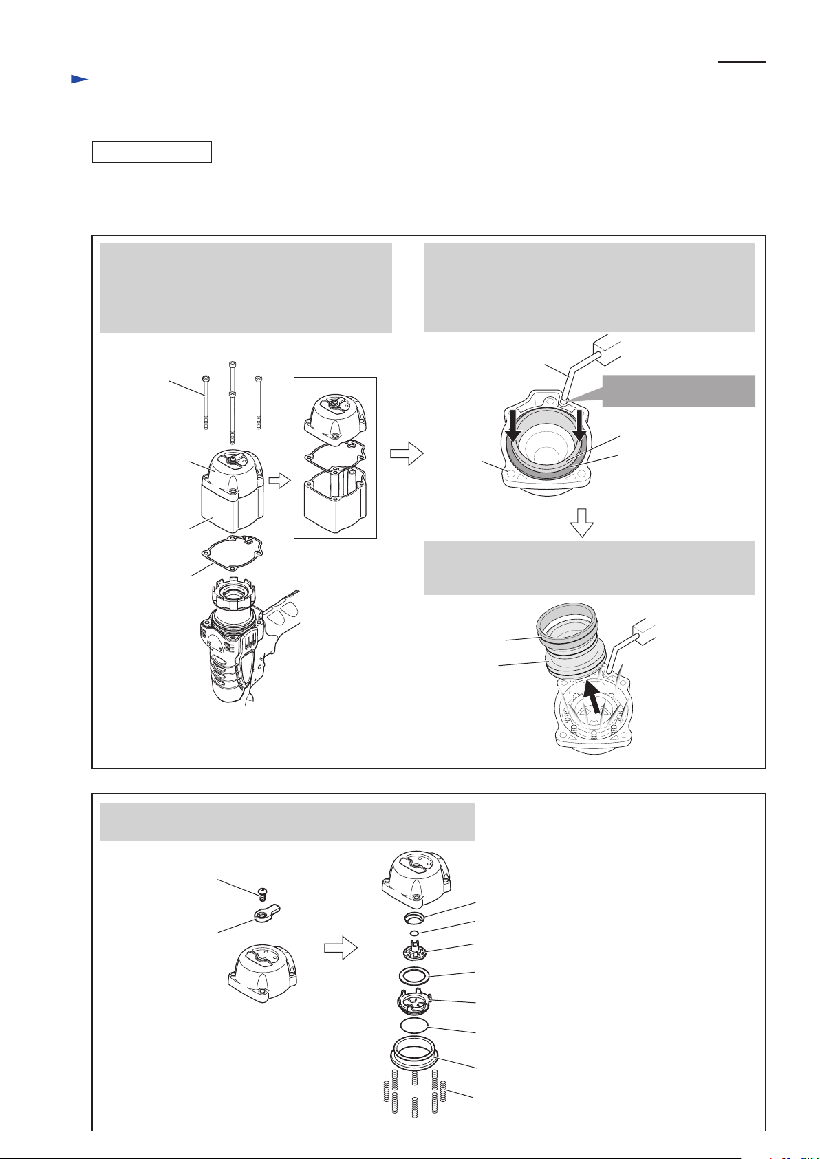
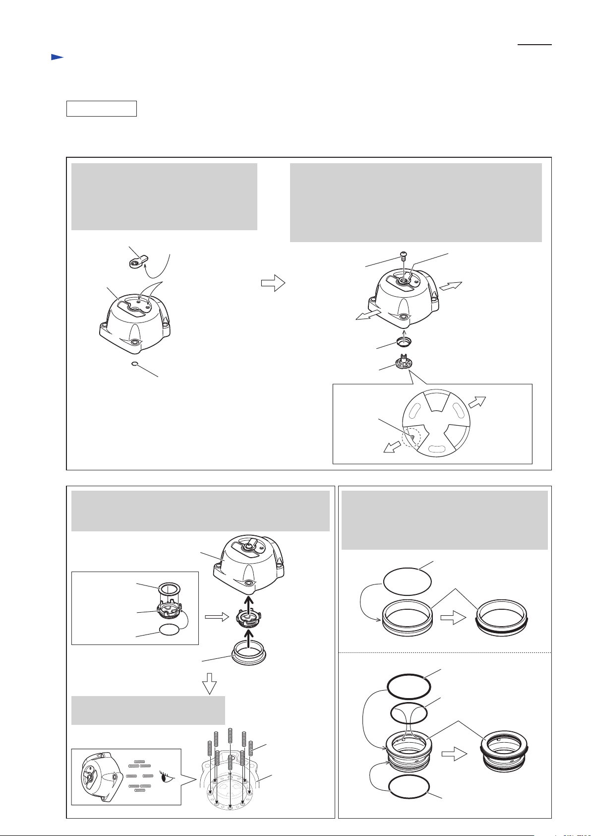
[3]-2. Top Cap Section
1) After removing Top cap and Top cap spacer from Housing, remove Head valve and Cylinder stay from Top cap
using air duster to blow air into the space between Top cap and Head valve using air pressure. (Fig. 3)
2) Remove Knob from Top cap, then disassemble the other parts from Top cap as illustrated in Fig. 4.
DISASSEMBLING
Cylinder stay
Head valve
1. By removing four M5x80 Hex socket head bolts
using 1R299, separate Top cap, Top cap spacer
and Top cap gasket from Housing. Then remove
Top cap and the other Top cap gasket from
Top cap spacer.
2. Turn Top cap upside down, then press down Head valve
and Cylinder stay firmly into Top cap with your palm
to make the air pressure as possible.
While pressing down Head valve and Cylinder stay,
insert nozzle of air duster into the hole of Top cap.
M4x8 Hex socket
button head bolt
(1 pc)
Cylinder stay
Head valve
Knob
By removing M4x8 Hex socket button head bolt and Knob,
the inner parts can be removed from Top cap as illustrated below.
Conical compression spring 10-15
O Ring 6
Change valve
Fig. 3
Fig. 4
Flat washer 19
Rear cushion
O Ring 22
Seal ring 22
Top cap
M5x80
Hex socket
head bolt
(4 pcs)
Top cap gasket
Top cap spacer
Insert nozzle of air duster
into this hole.
3. By blowing air into the space between Top cap and
Head valve through the hole, Cylinder stay and
Head valve can be separated from Top cap.
Nozzle of air duster
Top cap
P 5/20
Repair
[3] DISASSEMBLY/ASSEMBLY
[3]-2. Top Cap Section
1) Assemble Top cap section as described in Figs. 5, 6.
2) Assemble O rings to Cylinder stay and Head valve as described in Fig. 7.
ASSEMBLING
Fig. 5
Fig. 6 Fig. 7
click-stop concave
portion
protrusion
Knob
Set Knob on Top cap, with the protrusion on
its back fitting in either click-stop concave
portions on Top cap.
Then assemble O ring 6 to the insertion hole
for Change valve.
Assemble Conical compression spring 10-15 to Top cap
with the small end on Change valve side.
Then assemble Change valve to Top cap.
Note: When assembling Change valve to Top cap, place the
notch on the front side of Top cap as illustrated below
so that Change valve can engage with Knob easily.
Top cap
O Ring 6
Front side
Rear side
Change valve
Conical compression
spring 10-15
Knob
M4x8 Hex socket
button head bolt
Top cap
Seal ring
O Ring 54
Before assembling Cylinder stay and Head valve
to Top cap, mount O rings to them as illustrated
below, then apply such an amount of IDOFLEX
grease that they are covered with a thick layer of
the grease.
After mounting O ring 22 and Flat washer 19 on Rear cushion,
assemble Rear cushion to Top cap, then assemble Seal ring to
Top cap.
Set Compression spring 4 (8 pcs)
in the big diameter holes of Top cap.
Cylinder stay
Head valve
O Ring 47
O Ring 40
O Ring 45
Front side
notch
Rear side
Flat washer 19
Rear cushion
O Ring 22
Top cap
Compression
spring 4
P 6/20
Repair
[3] DISASSEMBLY/ASSEMBLY
[3]-2. Top Cap Section
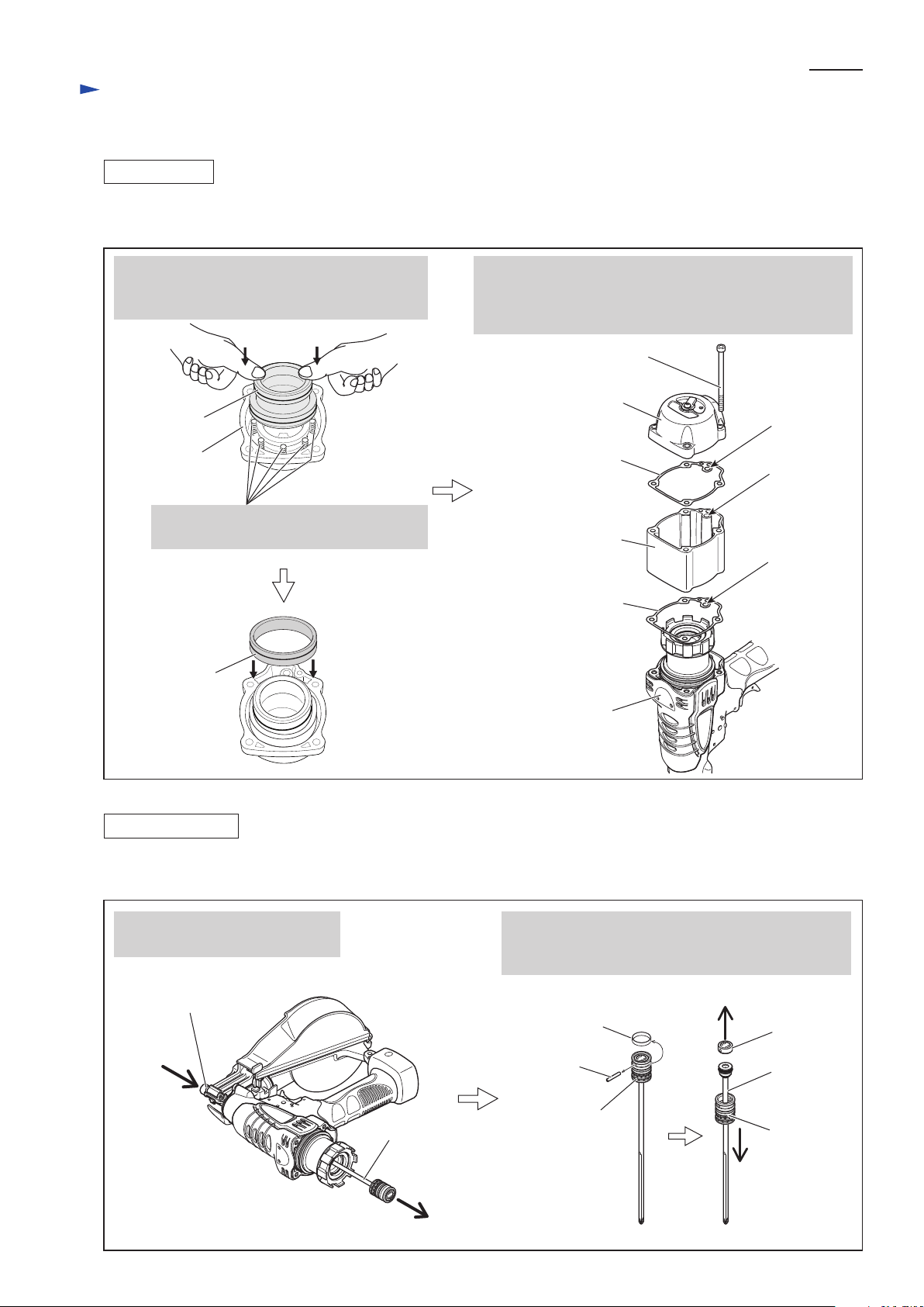
3) Assemble Head valve and Cylinder stay to Top cap (left in Fig. 8); assembling of Top cap section is now completed.
Then assemble Top cap section, Top cap spacer and Top cap gasket to Housing as illustrated on right in Fig. 8.
Fig. 8
Head valve
Top cap gasket
Top cap section
M5x80 Hex socket
head Bolt (4 pcs)
Top cap gasket
Housing
Top cap spacer
Assemble Head valve by pressing straight down
into Top cap.
Then assemble Cylinder stay to Top cap.
Top cap
Driver bit
Remove Driver bit by pushing it
from Driver guide complete side.
After removing Rubber ring 19 (white), pull off Pin 3.
Main piston and Piston cap can now be removed
as illustrated below.
Driver guide complete
Rubber ring 19
(white)
Main piston
Piston cap
Pin 3
Driver bit
Main piston
Fig. 9
[3]-3. Driver Bit
1) Disassemble Top cap and Top cap spacer from Housing as described on left in Fig. 3.
2) Disassemble Driver bit as described in Fig. 9.
ASSEMBLING
DISASSEMBLING
Note: Be careful not to fall down the eight
Compression springs set in Top cap.
Cylinder stay
Top cap spacer and two Top cap gaskets are directional
when assembled to Housing.
Make sure that the holes A, B, C are aligned with the hole
of Housing.
A
B
C
 Loading...