

Makita AN634H, AN635H Instruction Manual
INSTRUCTION MANUAL
MANUEL D'INSTRUCTION
MANUAL DE INSTRUCCIONES
Pneumatic Coil Nailer
Cloueur à rouleaux pneumatique
Clavadora Neumática de Carrete
AN634H
AN635H
IMPORTANT: Read Before Using.
IMPORTANT : Lire avant usage.
IMPORTANTE: Lea antes de usar.

ENGLISH (Original instructions)
SPECIFICATIONS
Model: AN634H AN635H
Air pressure 1.18 - 2.26 MPa (170 - 320 PSIG)
Nail length Wire-collated coil nail 32 mm - 65 mm (1-1/4″ - 2-1/2″)
Sheet-collated coil nail 32 mm - 65 mm (1-1/4″ - 2-1/2″)
Nail capacity Wire-collated coil nail 200 pcs - 400 pcs
Sheet-collated coil nail 200 pcs
Minimum hose diameter 4.0 mm (5/32″)
Dimensions (L x W x H) 284 mm x 125 mm x 296 mm
Net weight 2.1 kg (4.7 lbs) 2.2 kg (4.9 lbs)
• Due to our continuing program of research and development, the specications herein are subject to change
without notice.
• Specications may differ from country to country.
• Weight according to EPTA-Procedure 01/2003
(11-1/8″ x 4-7/8″ x 11-5/8″)
297 mm x 125 mm x 296 mm
(11-3/4″ x 4-7/8″ x 11-5/8″)
SAFETY WARNINGS
Important safety instructions
For personal safety and proper operation and maintenance of the tool, read this instruction manual
carefully before using the tool.
WARNING: WHEN USING THIS TOOL, BASIC
SAFETY PRECAUTIONS SHOULD ALWAYS BE
FOLLOWED TO REDUCE THE RISK OF PERSONAL
INJURY, INCLUDING THE FOLLOWING:
READ ALL INSTRUCTIONS.
Personal Protective Equipment
1.
Always wear safety glasses to avoid eye injury
from dust or fasteners. The safety glasses should
conform with the requirements of ANSI Z87.1.
WARNING:It is an employer's responsibility
to enforce the use of safety eye protection
equipment by the tool operators and by other
persons in the immediate working area.
2. Wear hearing protection to protect your ears
against exhaust noise and head protection.
Also wear light but not loose clothing. Sleeves
should be buttoned or rolled up. No necktie
should be worn.
Flammable Atmospheres
1. Do not operate tool in explosive atmospheres,
such as in the presence of ammable liquids,
gases or combustible dust.
Tool modication
1. The tool should not be modied unless autho-
rized in the tool manual or approved in writing
by the tool manufacturer.
Tool maintenance
1. Refer to the tool maintenance instructions for
detailed information on the proper maintenance of a tool.
Recommended fasteners and accessories
1. Use only fasteners made or recommended by
the tool manufacturer, or fasteners that perform equivalently to those recommended by
the manufacturer.
2. Use only accessories made or recommended
by the tool manufacturer, or accessories that
perform equivalently to those recommended
by the manufacturer.
Inspect tool before operating to:
1. Use only power source specied in the instruc-
tion manual.
Operate the tool within the specied air pressure on the tool label for safety and longer tool
life. Do not exceed the recommended max.
operating pressure. The tool should not be
connected to a source whose pressure potentially exceeds 3.39 MPa (480 PSIG).
2. Never use the tool with other than compressed
air. If bottled gas (carbon dioxide, oxygen,
nitrogen, hydrogen, air, etc.) or combustible
gas (hydrogen, propane, acetylene, etc.) is
used as a power source for this tool, the tool
will explode and cause serious injury.
3. Always check the tool for its overall condition
and loose screws before operation. Tighten as
required.
4. Make sure all safety systems are in working
order before operation. The tool must not
operate if only the trigger is pulled or if only
the contact element is pressed against the
wood. It must work only when both actions are
performed. Test for possible faulty operation
with fasteners unloaded and the contact element in fully pulled position.
5. Always check contact element as instructed in
this manual. Fasteners may be driven accidentally if the safety mechanism is not working
correctly.
2 ENGLISH

Operating controls
1. Do not use a tool with missing or damaged
safety warning label(s.)
2. A tool that is not in proper working order must
not be used. Tags and physical segregation
shall be used for control.
3.
Do not remove, tamper with, or otherwise cause
tool operating controls to become inoperable.
4. Do not operate tool if any portion of the tool
operating controls is inoperable, disconnected, altered, or not working properly.
Tool handling
1. Only persons who have read and understand
the tool operating/safety instructions should
operate the tool.
2. Always assume that tool contains fasteners.
3. Do not point tool toward yourself or anyone
whether it contains fasteners or not.
4. Keep bystanders and children away while
operating tool.
5. Do not actuate tool unless tool is placed rmly
against the workpiece.
6. Respect tool as a working implement.
7. Do not engage in horseplay.
8. Stay alert, focus on your work and use com-
mon sense when working with tools.
9. Do not use tool while tired, after having consumed drugs or alcohol, or while under the
inuence of medication.
10. Do not overreach. Keep proper footing and
balance at all times.
11.
Do not hold or carry tool with a nger on the trigger.
12. Drive fasteners into proper work surface only.
13. Do not drive fasteners into other fasteners.
14. After driving a fastener, tool may spring back
(“recoil”) causing it to move away from the
work surface. To reduce risk of injury always
manage recoil by:
a) always maintaining control of tool.
b) allowing recoil to move tool away from
work surface.
c)
not resisting recoil such that tool will
be forced back into the work surface. In
“Contact Actuation Mode,” if workpiece
contact is allowed to re-contact work surface before the trigger is released, an unintended discharge of a fastener will occur.
d) keeping face and body parts away from
15. When working close to an edge of a workpiece
16. Keep hands and body away from fastener
17. Do not load tool with fasteners when any one
18. Do not operate tool with any power source
19. Do not operate tool with any operating pres-
tool.
or at steep angles use care to minimize chip-
ping, splitting or splintering, or free ight or
ricochet of fasteners, which may cause injury.
discharge area of tool.
of the operating controls is activated.
other than that specied in tool operating/
safety instructions.
sure other than that specied in tool operating/
safety instructions.
20. Always select an actuation system that is
appropriate to the fastener application and the
training of the operator.
21. Use extra caution when driving fasteners into
existing walls or other blind areas to prevent
contact with hidden objects or persons on
other side (e.g., wires, pipes.)
22. Do not lift, pull or lower tool by the hose.
Disconnecting tool
Disconnect tool from the power source when:
1. Not in use;
2. Performing any maintenance or repairs;
3. Clearing a jam;
4. Elevating, lowering or otherwise moving the
tool to a new location;
5. Tool is outside of the operator’s supervision or
control; or
6. Removing fasteners from the magazine.
Additional safety instructions
1. The area should be sufciently illuminated to
assure safe operations. The area should be
clear and litter-free.
2. There may be local regulations concerning
noise which must be complied with by keeping
noise levels within prescribed limits. In certain
cases, shutters should be used to contain
noise.
3. Check walls, ceilings, oors, roong and
the like carefully to avoid possible electrical
shock, gas leakage, explosions, etc. caused by
striking live wires, conduits or gas pipes.
4. On rooftops and other high locations, drive
fasteners as you move forward. It is easy to
lose your footing if you drive fasteners while
inching backward. When driving against perpendicular surface, drive fasteners from the
top to the bottom. You can perform the operations with less fatigue by doing so.
5. Do not leave the loaded tool or the air compressor under pressure for a long time out in
the sun. Be sure that dust, sand, chips and
foreign matter will not enter the tool in the
place where you leave it setting.
6. Perform cleaning and maintenance right after
nishing the job. Keep the tool in tip-top condition. Lubricate moving parts to prevent rusting
and minimize friction-related wear. Wipe off all
dust from the parts.
7. Do not disconnect the air hose with a nger
on the trigger. An unexpected driving will cause
serious injury when the air hose is connected.
8. When you drop or strike the tool, check the
tool damage or crack and make sure that
safety systems are in working order before
operation. As there is high pressure inside the
tool, failure to do so will cause serious injury.
9. Ask Makita's Authorized service centers for
periodical inspection of the tool.
10. To maintain product SAFETY and RELIABILITY,
maintenance and repairs should be performed
by Makita Authorized or Factory Service
Centers, always using Makita replacement
parts.
SAVE THESE INSTRUCTIONS.
3 ENGLISH
WARNING: MISUSE or failure to follow the
safety rules stated in this instruction manual may
cause serious personal injury.
Symbols
The followings show the symbols used for tool.
Read and understand tool labels and manual. Failure to follow warnings could result
in death or serious injury.
Operators and others in work area must
wear safety glasses with side shields.
Keep ngers away from trigger when
not driving fasteners to avoid accidental
discharge.
PARTS DESCRIPTION
1
2
3
5
► 1. Trigger 2. Trigger lock lever 3. Hook 4. Magazine
cap 5. Nose adapter (contact element)
4
INSTALLATION
Selecting compressor
5
4
3.5
3
2
2
1
0
0 10 20 30 40 50 60
1
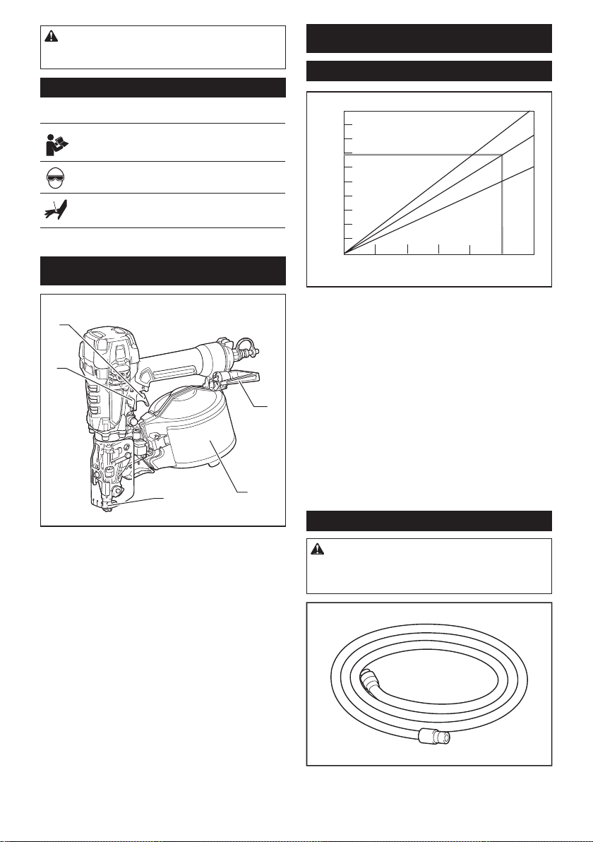
1. Nailing frequency (times/min) 2. Compressor air out-
put per minute (CFM (ft3 /min.)) 3. 2.26 MPa (320 PSIG)
4. 1.76 MPa (250 PSIG) 5. 1.18 MPa (170 PSIG)
The air compressor must comply with the requirements
of ANSI B19.3.
Select a compressor that has ample pressure and air
output to assure cost-efcient operation. The graph
shows the relation between nailing frequency, applica-
ble pressure and compressor air output.
Thus, for example, if nailing takes place at a rate of
approximately 50 times per minute at a compression of
1.76 MPa (250 PSIG), a compressor with an air output
over 3.5 CFM ( ft
Pressure regulators must be used to limit air pressure to the
rated pressure of the tool where air supply pressure exceeds
the tool's rated pressure. Failure to do so may result in seri-
ous injury to tool operator or persons in the vicinity.
3
/minute) is required.
Selecting air hose
CAUTION: Low air output of the compressor,
or a long or smaller diameter air hose in relation
to the nailing frequency may cause a decrease in
the driving capability of the tool.
3
4
5
Use a high pressure resistant air hose.
Use an air hose as large and as short as possible to
assure continuous, efcient nailing operation.
4 ENGLISH
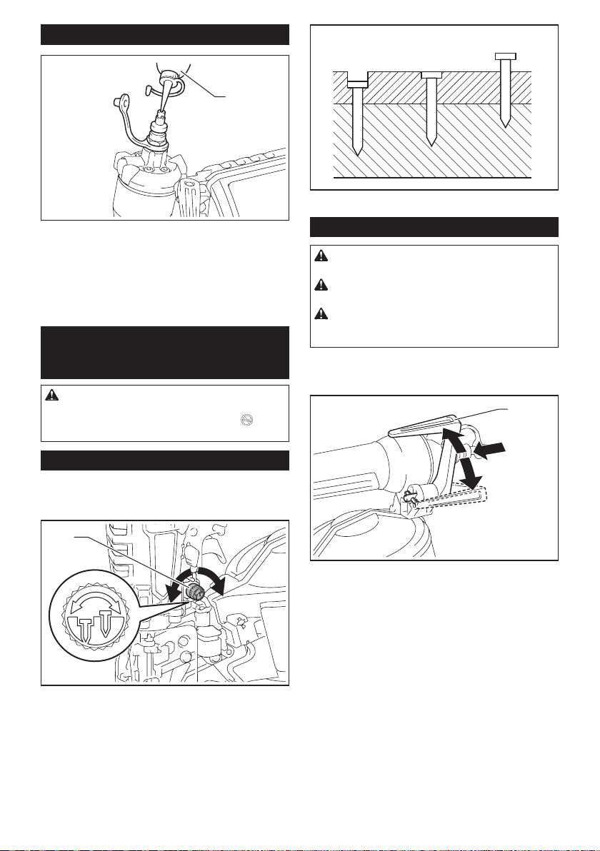
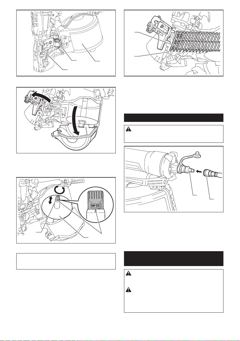
Lubrication
123
1
► 1. Too deep 2. Flush 3. Too shallow
► 1. Pneumatic tool oil
Oil the tool with pneumatic tool oil by placing two or
three drops into the air tting. This should be done
before and after use.
For proper lubrication, the tool must be red a couple of
times after pneumatic tool oil is introduced.
FUNCTIONAL
DESCRIPTION
CAUTION: Before adjusting or checking func-
tion on the tool, always lock the trigger by turning
the trigger lock lever to the lock position , and
disconnect the air hose from the tool.
Adjusting depth of nailing
This toll has the adjuster of the nailing depth. To modulate the nailing depth, turn the adjuster to the proper
depth.
1
Hook
CAUTION: Always disconnect the hose when
hanging the tool using the hook.
CAUTION: Never hook the tool at high loca-
tion or on potentially unstable surface.
CAUTION: Do not hang the hook from the
waist belt. If the nailer accidentally drops, it may
result in misring and personal injuries.
The hook is useful for hanging up the tool temporarily.
The hook can be turned while pushing the bottom to the
desired angle.
1
► 1. Hook
Furthermore, this hook can be installed on either side
of the tool.
To change the installation position, unscrew the bolt
with a screwdriver and remove the nut. Install the hook
on another side and then secure it rmly with the bolt
and the nut.
► 1. Adjuster
The adjustable range is 8.0 mm (5/16"). (One full turn
allows 1.6 mm (1/16") adjustment.)
5 ENGLISH
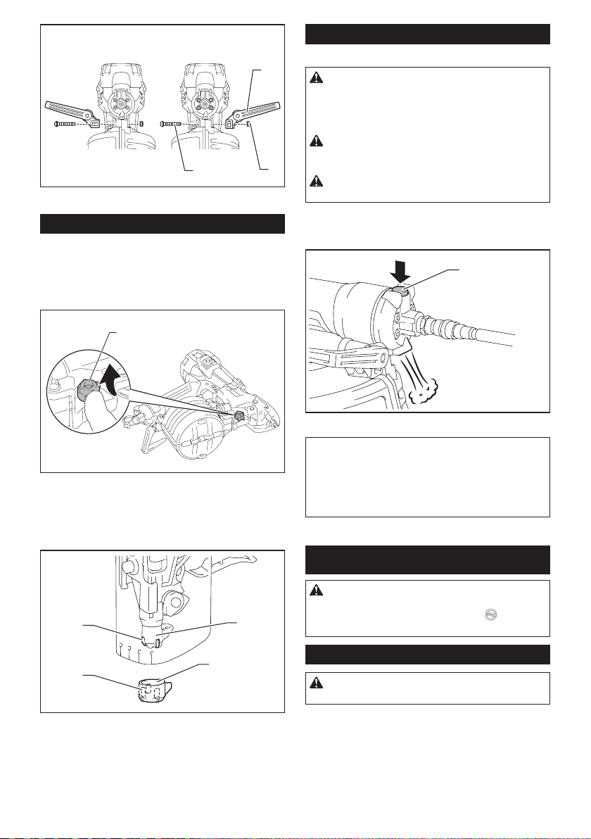
1
2
► 1. Hook 2. Bolt 3. Nut
3
Nose adapter
To prevent the surface of workpiece from being
scratched or damaged, use the nose adapter.
To detach the nose adapter from its housing base, pull
the nose adapter with your thumb in the direction of the
arrow.
1
Air duster
For Model AN635H
CAUTION: Do not aim the ejection port of the
air duster to someone. Also, keep your hands and
foot away from the ejection port. If the air duster
button is accidentally pushed, it may cause a personal injury.
CAUTION: Always check your surroundings
before using the air duster. Blown dust or objects
may hit someone.
CAUTION: Do not connect or disconnect the
air hose while pushing the air duster button.
The air supplied to the tool can also be used as an air
duster. You can clean the work area by pressing the
button on the grip end.
1
► 1. Button
► 1. Nose adapter
To attach the nose adapter to the contact element,
press it onto the contact element until the recessed
parts in three places inside the nose adapter t in three
protrusions of the contact element.
3
2
1
4
► 1. Nose adapter 2. Contact element 3. Protrusion
4. Recessed part
NOTICE: After using the air duster, the driving force
of the tool will temporarily decline. Wait until the air
pressure recovers in this case.
NOTICE: Perform a test blow if you use the air
duster immediately after the oil was applied. The oil
may be sprayed with the air.
ASSEMBLY
CAUTION: Before carrying out any work on
the tool, always lock the trigger by turning the
trigger lock lever to the lock position , and
disconnect the air hose from the tool.
Loading nailer
CAUTION: Do not use deformed nails or
linked sheet.
1. Disconnect the air hose.
2. Depress the latch lever and open the door and
magazine cap.
6 ENGLISH
2
1
3
2
► 1. Latch lever 2. Door 3. Magazine cap
3. Turn the adjust shaft and set the step of the
change plate suitable for the nail length. Make sure that
the arrow points to the corresponding graduation incre-
ment of the nail length marked on the adjust shaft.
2
► 1. Change plate 2. Adjust shaft 3. Arrow
3
1
NOTICE: If the tool is operated with the change
plate set to the wrong step, it may result in poor nail
feeding or tool malfunction.
4. Place the nail coil over the change plate and
uncoil enough nails to reach the nail rail.
Then place the rst nail in the nail rail and the second
nail in the feed claw. Also, place other uncoiled nails on
feeder body.
1
► 1. Nail rail 2. Feed claw
5. Check that the nail coil is set properly in the
magazine.
6. Close the magazine cap carefully. Then with
depressing the latch lever, close the door until the latch
lever locks.
Connecting air hose
CAUTION: Do not connect the air hose with
a nger on the trigger. An unexpected driving will
cause serious injury.
1
► 1. Air tting 2. Air socket
Slip the air socket of the air hose onto the air tting on
the nailer. Be sure that the air socket locks rmly into
position when installed onto the air tting.
A hose coupling must be installed on or near the tool in
such a way that the pressure reservoir will discharge at
the time the air supply coupling is disconnected.
2
Changing the trigger for contact
actuation mode
CAUTION: Always disconnect the air hose
and unload the tool with nails before replacing
the trigger.
CAUTION: After the trigger replacement,
always check that the tool operates properly
before actual work. Do not load the tool with any
nails before checking the function to avoid unexpected nailing.
7 ENGLISH
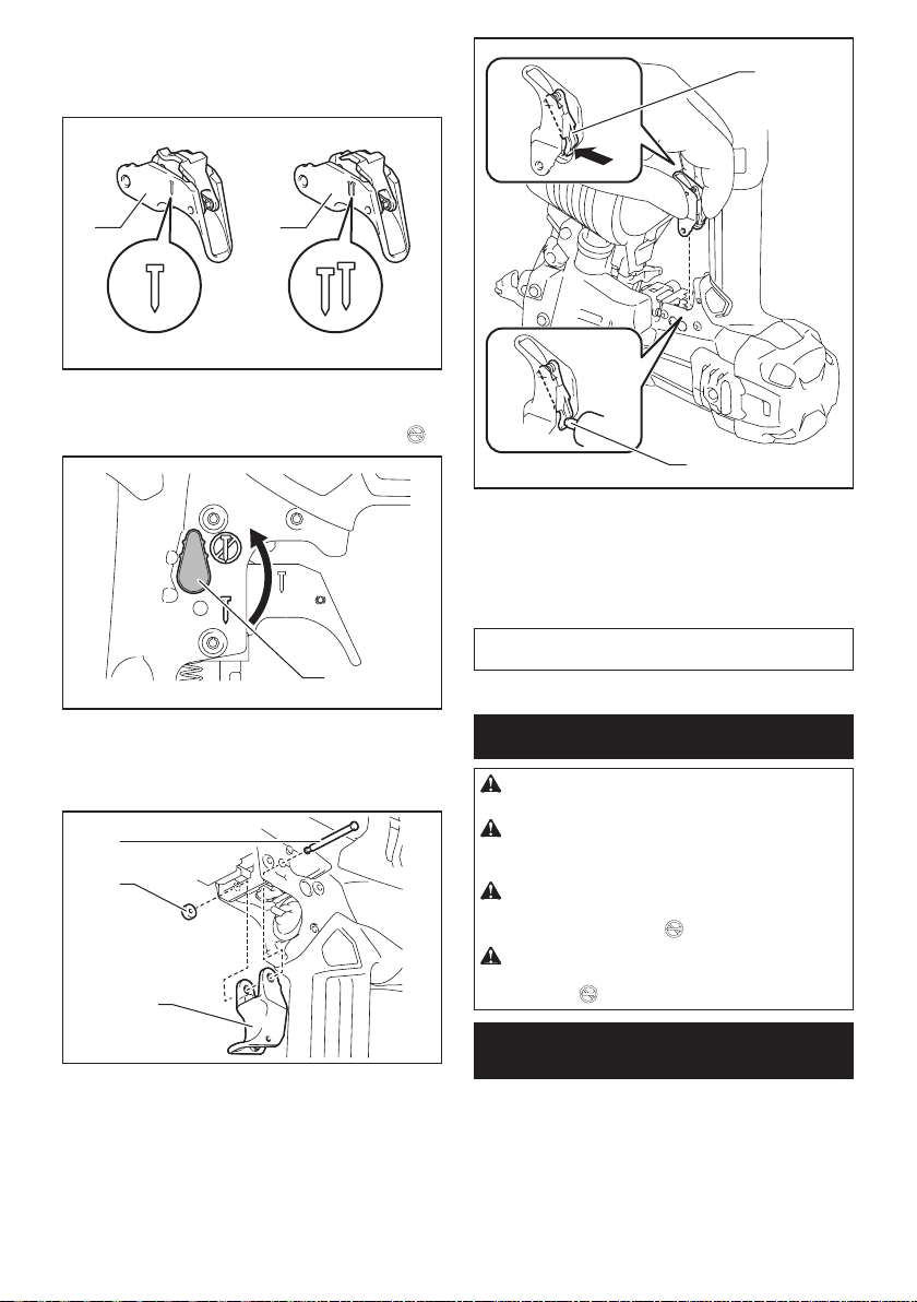
The trigger for single sequential actuation mode is
factory-installed. To change the nailing mode to contact
actuation, replace the trigger part with the one for con-
tact actuation.
1
1
► 1. Trigger for single sequential actuation (Gray
color) 2. Trigger for contact actuation (Black color)
1. Turn the trigger lock lever to the lock position
2
1
► 1. Trigger lock lever
2. Push the pin securing the trigger from the ure-
thane washer side, and then remove the urethane
washer. Then pull out the pin and remove the trigger.
1
2
3
► 1. Pin 2. Urethane washer 3. Trigger
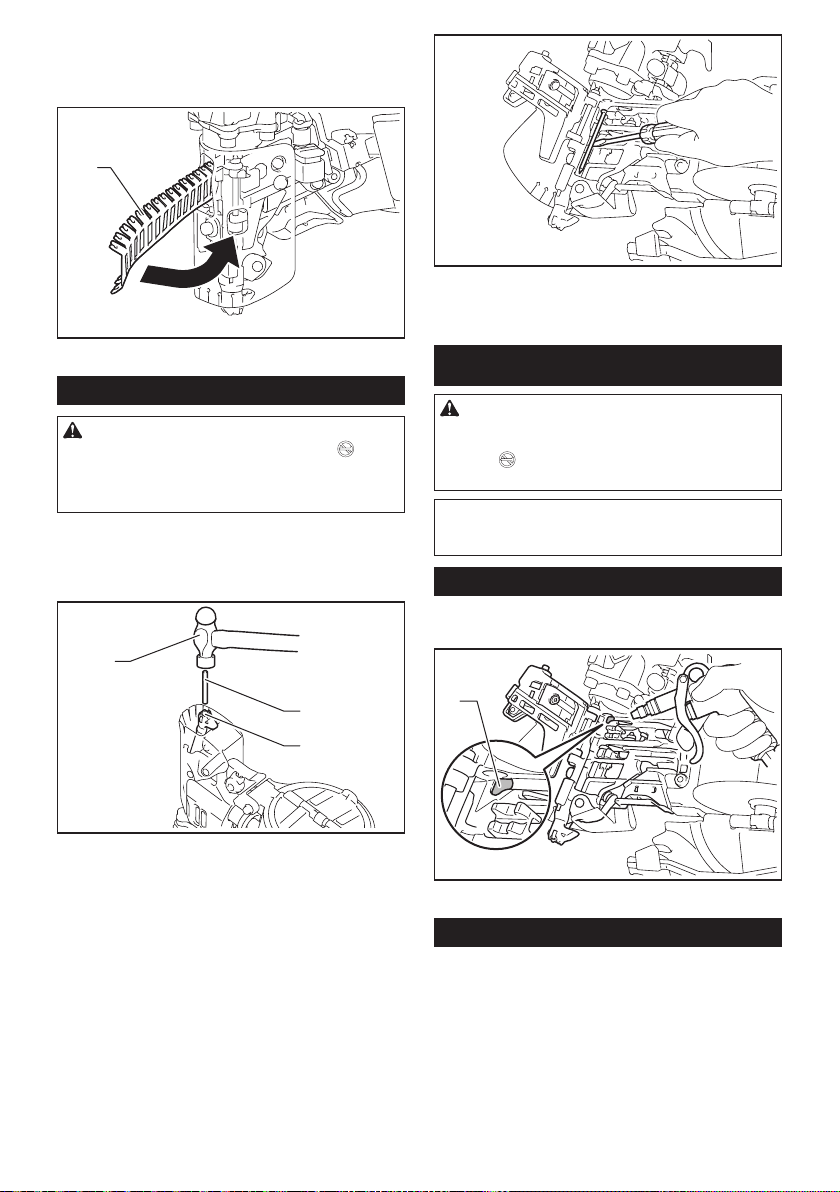
3. Set the trigger assembly for contact actuation.
With pushing in the hinged part inward, set the trigger
so that the hinged part is under the rod of the valve in
the housing.
.
2
► 1. Hinged part 2. Rod of the valve
4. Insert the pin to the hole and secure it by urethane
washer.
5. Connect the air hose, and make sure that the
tool operates properly. Refer to the section “Checking
proper action before operation”.
NOTE: To set back to single sequential actuation,
follow the procedures for changing the trigger above.
OPERATION
CAUTION: Make sure all safety systems are in
working order before operation.
CAUTION: When operating the tool, do not
close the face to the tool. Also keep hands and
feet away from the ejection port area.
CAUTION: When not operating the tool,
always lock the trigger by turning the trigger lock
lever to the lock position
CAUTION: Make sure that the trigger is
locked when the trigger lock lever is set to the
lock position .
Checking proper action before
operation
Before operation, always check following points.
— Make sure that the tool does not operate only by
connecting the air hose.
— Make sure that the tool does not operate only by
pulling the trigger.
— Make sure that the tool does not operate only by
placing the contact element against the workpiece
without pulling the trigger.
8 ENGLISH
.
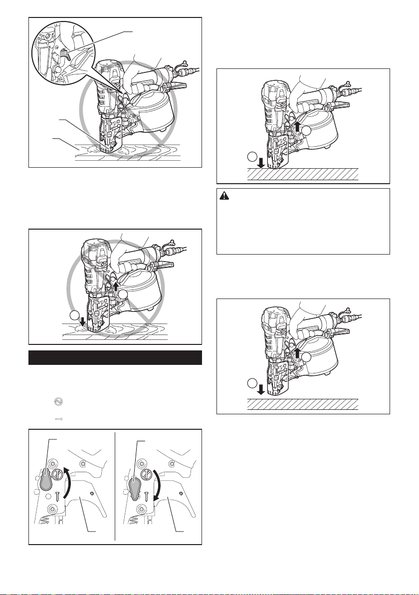
3
1
2
► 1. Contact element 2. Workpiece 3. Trigger (not
pulled)
— In single sequential actuation mode, make sure
that the tool does not operate when pulling the
trigger rst and then placing the contact element
against the workpiece.
1
Single sequential actuation
Place the contact element against the workpiece and
pull the trigger fully.
After nailing, release the contact element, and then
release the trigger.
2
1
CAUTION: Do not place the contact element
against the workpiece with excessive force. Also,
pull the trigger fully and hold it on for 1-2 seconds
after nailing.
Even in the “Single sequential actuation” mode, halfpulled trigger causes an unexpected nailing, when the
contact element re-contacts the workpiece.
Contact actuation
Pull the trigger rst and then place the contact element
against the workpiece.
2
Nailing method
To prevent the trigger from being accidentally pulled,
the trigger lock lever is provided.
To lock the trigger, turn the trigger lock lever to the lock
position
To use the tool, turn the trigger lock lever to the unlock
position .
► 1. Trigger lock lever 2. Trigger
.
1
1
2 2
1
2
9 ENGLISH
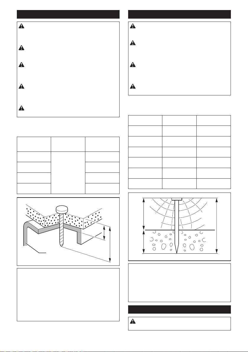
Nailing on steel plate
Nailing on concrete
WARNING: When nailing on the C-shaped
steel, limit the thickness to 2.3 mm (3/32″) or
thinner. Otherwise the tool will bounce severely and
a nail struck back, causing serious injuries.
WARNING: Use hardened nails only for steel
plate. Using other purposed nails may cause serious
injuries.
WARNING: When nailing, hold the tool so that
it stands upright to the driving surface. Slanted
nailing may cause nails to strike back, causing serious injuries.
WARNING: Do not use the tool for fastening
a corrugated plate or the C-shaped steel directly.
It may cause nails to strike back, causing serious
injuries.
WARNING: Do not use the tool for nailing on
ceiling or roof.
Choose and use nails 10 mm (3/8″) or much longer than
total thickness of all workpiece to be fastened. Refer to
the table below.
Material thick-
ness including
C-shaped steel (A)
9 mm - 22 mm
(11/32″ - 7/8″)
10 mm - 27 mm
(3/8″ - 1-1/16″)
14 mm - 35 mm
(9/16″ - 1-3/8″)
15 mm - 40 mm
(5/8″ - 1-9/16″)
C-shaped steel (B)
thickness
1.6 mm - 2.3 mm
(1/16″ - 3/32″)
Nail length (C)
32 mm (1-1/4″)
38 mm (1-1/2″)
45 mm (1-3/4″)
50 mm (2″)
WARNING: Use hardened nails only for con-
crete. Using other purposed nails may cause serious
injuries.
WARNING: Do not nail directly on the con-
crete or do not fasten directly the steel plate to
the concrete. It may cause concrete fragments to y
off or nails to strike back, causing serious injuries.
WARNING: When nailing, hold the tool so that
it stands upright to the driving surface. Slanted
nailing may cause concrete fragments to y off or
nails to strike back, causing serious injuries.
WARNING: Do not use the tool for fastening
an object to hang something such as sewer pipe.
Choose and use nails so that the penetration depth into
concrete ranges 10 mm (3/8″) - 15 mm (5/8″). Refer to
the table below.
Wood thick-
ness (A)
20 mm (3/4″) 32 mm (1-1/4″) Approx. 12 mm
25 mm (1″) 38 mm (1-1/2″) Approx. 13 mm
30 mm (1-3/16″) 42 mm / 45 mm
35 mm (1-3/8″) 50 mm (2″) Approx. 15 mm
45 mm (1-3/4″) 57 mm (2-1/4″) Approx. 12 mm
50 mm (2″) 65 mm (2-1/2″) Approx. 15 mm
Nail length (B) Penetration depth
(1-5/8″ / 1-3/4″)
into concrete (C)
(1/2″)
(1/2″)
Approx. 12 mm / 15
mm (1/2″ / 5/8″)
(5/8″)
(1/2″)
(5/8″)
A
C
B
NOTICE: Depending on the hardness and
total thickness of all workpiece in combination,
enough fastening may not be obtained. Nailing on
steel plate with excessive depth may extremely
reduce the fastening force. Before nailing, adjust
the nailing depth properly.
NOTICE: Nailing on the steel plate makes the
driver prematurely worn out and it may cause nail
jamming. When the driver is worn, replace it with a
new one.
A
B
C
NOTICE: Use the tool only for soft concrete
built up not so long before. Driving nails into hard
concrete may cause nail bending or nailing into insuf-
cient depth.
NOTICE: When penetrating into concrete
deeper than 15 mm (5/8″), nails may not be driven
sufciently.
Cutting linked sheet
CAUTION: Always disconnect the air hose
from the tool before removing the linked sheet.
10 ENGLISH
When using linked sheet nails, the linked sheet will be
ejected from the driver guide as you drive the nails.
Tear away the ejected sheet by twisting as shown in the
gure.
1
► 1. Ejected linked sheet
Removing jammed nails
CAUTION: Always lock the trigger by turning
the trigger lock lever to the lock position , and
disconnect the hose before removing jammed
nails. Also remove the nails from the magazine
before cleaning a jam.
1. Depress the latch lever and open the door. Open
the magazine cap and remove the nail coil.
2. Insert a small metal rod into the nail ejection port
and hit it with a hammer lightly.
3
4. Reset the nail coil and close the magazine cap
and the door.
MAINTENANCE
CAUTION: Before attempting to perform
inspection or maintenance, always lock the trigger by turning the trigger lock lever to the lock
position , and disconnect the air hose from the
tool.
NOTICE: Never use gasoline, benzine, thinner,
alcohol or the like. Discoloration, deformation or
cracks may result.
Cleaning of tool
Iron dust that adhere to the magnet can be blown off by
using an air duster.
1
2
► 1. Metal rod 2. Nail ejection port 3. Hammer
3. Remove the jammed nail with a at-blade screw-
driver or other similar tool.
1
► 1. Magnet
Storage
When not in use, disconnect the hose. Then cap the air
tting with the cap. Store the nailer in a warm and dry
place.
11 ENGLISH

1
1
2
► 1. Cap
Maintenance of compressor, air set
and air hose
After operation, always drain the compressor tank and
the air lter. If moisture is allowed to enter the tool,
it may result in poor performance and possible tool
failure.
1
► 1. Drain cock
1
► 1. Oiler 2. Pneumatic oil
Keep the air hose away from heat (over 60°C, over
140°F), away from chemicals (thinner, strong acids or
alkalis). Also, route the hose away from obstacles which
it may become dangerously caught on during operation.
Hoses must also be directed away from sharp edges and
areas which may lead to damage or abrasion to the hose.
To maintain product SAFETY and RELIABILITY,
repairs, any other maintenance or adjustment should
be performed by Makita Authorized or Factory Service
Centers, always using Makita replacement parts.
OPTIONAL
ACCESSORIES
CAUTION: These accessories or attachments
are recommended for use with your Makita tool
specied in this manual. The use of any other
accessories or attachments might present a risk of
injury to persons. Only use accessory or attachment
for its stated purpose.
If you need any assistance for more details regarding
these accessories, ask your local Makita Service Center.
• Nails
• Air hose
• Safety goggles
• Nose adapter
NOTE: Some items in the list may be included in the
tool package as standard accessories. They may
differ from country to country.
► 1. Air lter
Check regularly to see if there is sufcient pneumatic
oil in the oiler of the air set. Failure to maintain sufcient
lubrication will cause O-rings to wear quickly.
MAKITA LIMITED ONE YEAR
WARRANTY
Warranty Policy
Every Makita tool is thoroughly inspected and tested
before leaving the factory. It is warranted to be free of
defects from workmanship and materials for the period
of ONE YEAR from the date of original purchase.
Should any trouble develop during this one year period,
return the COMPLETE tool, freight prepaid, to one
of Makita’s Factory or Authorized Service Centers. If
inspection shows the trouble is caused by defective
workmanship or material, Makita will repair (or at our
option, replace) without charge.
12 ENGLISH
 Loading...