

Page 1

Models No.
Description
CONCEPT AND MAIN APPLICATIONS
Specification
Optional accessories
AC310H
Air Compressor
Dimensions: mm (")
Width (W)
Height (H)
Length (L) 476 (18-3/4)
507 (20)
375 (14-3/4)
W
L
H
This model has been launched as Makita first HP(high pressure) air compressor.
1,500W high output motor generates maximum 2.58MPa air flow performance to
exploit the full potential of HP pneumatic tools such as nailer, stapler, screwdriver
and impact driver.
Four couplers are on the front. The two couplers are for HP pneumatic tools,
the others are for RP (regular pressure) pneumatic tools.
Guard with seven bumpers is equipped to protect their couplers and body.
P 1/ 7
PRODUCT
T
ECHNICAL INFORMATION
Continuous Rating (W)
Voltage (V) Cycle (Hz)
Input Output
Max. Output (W)
120
220-240
13.0
7.0
60
50
---
1,800 1,500
1,500
Current (A)
875
875
Model No.
Specifications
Weight according to EPTA procedure: kg (lbs)
Power supply cord: m (ft)
Tank capacity
Continuous rating output: W
Rated amperage for North America: A
Motor
Horsepower: HP
Type
RPM: min-1
2.5
Air flow performance: L/min at 0.75MPa
90
Noise: dB(A)
tested according to outdoor noise directive
Motor thermal overload protector
Insulation
Max air pressure in Tank: Mpa (psi)
Carrying tool
Air hose assembly
Hose reel
None of Standard equipment
Note: Standard equipment may vary by countries.
Air pressure in Tank when restarting: Mpa (psi)
for high pressure
for regular pressure
Operating air pressure: MPa (psi)
AC310H
2.8 (410)
2.3 (330)
Air pressure
through Coupler: Mpa
0 ~ 2.58
0 ~ 0.91
1,500
4-pole induction motor
90
Yes
by grounding
6.2 (1.6)
1.8 (5.9)
36 (79.4)
0.98~2.26 (140 ~ 320)
13
1,700(60Hz) / 1,420(50Hz)
Standard equipment
Page 2

P 2/ 7
Repair
CAUTION: Repair the machine in accordance with “Instruction manual” or “Safety instructions”.
[1] NECESSARY REPAIRING TOOLS
[2] REPLACING
[2]-1. Filter
[2]-2. Filter
Fig. 1
Fig. 2
Fig. 4 Fig. 5
Fig. 3
Code No. Description Use for
1R230 1/4" Hex. shank bit for M6 Removing M6 Hex socket head bolt
1R231 1/4" Hex. shank bit for M8 Removing M8 Hex socket head bolt
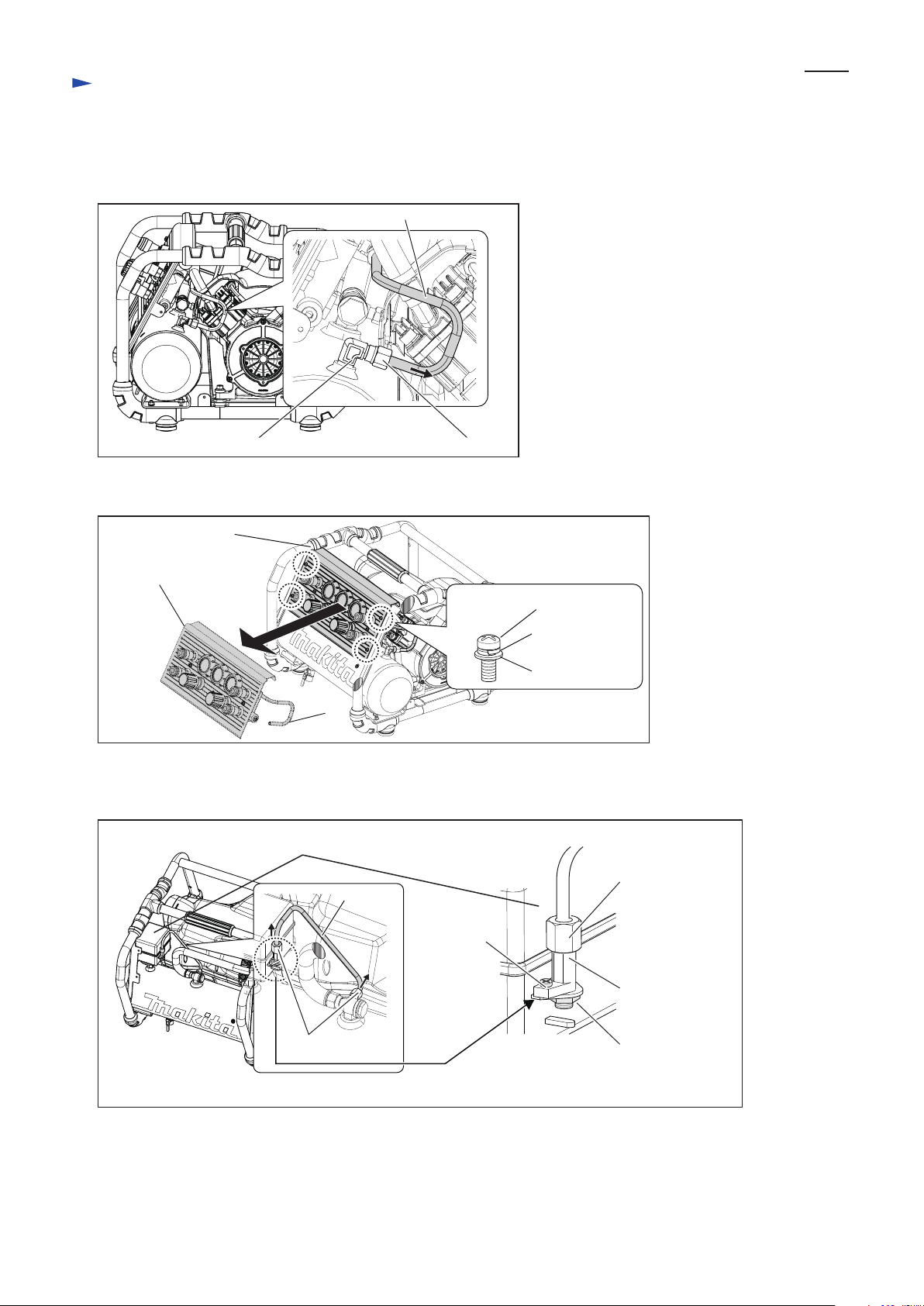
1) Loosen five M5x10 Pan head screws, then remove Side panel with Side panel cover.
2) Loosen three 4x18 Tapping screws, then remove Filter cover. (Fig. 2)
Filter can be removed as illustrated in Fig. 3.
After removing Side panel with Side panel cover, loosen Cover of Check valve section with box wrench 19. (Fig. 4)
Check valve can be removed. (Fig. 5)
Remove five M5x10 Pan head screws
designated with arrows.
Side panel with Side panel cover
4x18 Tapping screw
(3pcs.)
Filter cover
Filter
Note: Do not loosen two M5x10
Pan head screws in two circles.
Cover of Check valve section
Cover of
Check valve sectionCheck valve
M5x10 Pan head screw
Spring washer 5
Flat washer 5
Page 3
P 3/ 7
Repair
[2] REPLACING
[2]-3. Unloading valve
Fig. 6
Fig. 7
Fig. 8
1) Loosen M8 Ring nut with Spanner 17, then remove Pipe 8 from Elbow 8-R1/4. (Fig. 6)
2) Loosen four M5x10 Pan head screws, then remove Front panel assembly from Frame complete. (Fig. 7)
3) Loosen two Ring nuts 6 with Spanner 13, then remove Pipe 6.
Loosen Screw and Nut (that are components of Switch assembly). Unloading valve can be removed. (Fig. 8)
M8 Ring nutElbow 8-R1/4
Pipe 8
M5x10 Pan head screw
Spring washer 5
Flat washer 5
Frame complete
Pipe 8
Front panel assy (RC1/4)
Ring nut 6 (2pcs.)
Ring nut 6
Switch assembly
Pipe 6
Nut
Unloading valve
Screw
Page 4

P 4/ 7
Repair
Fig. 9
Fig. 10
Fig. 11
1) After removing Side panel with Side panel cover, loosen two Ring nut 10 and remove Pipe 10. (Fig. 9)
2) Loosen nine 4x18 Tapping screws, then separate Motor cover A complete from Motor cover C. (Fig. 10)
4x18 Tapping screws (9pcs.)
3) Lift up and slide Motor cover A complete along gray arrow direction so that the side of Cylinder head L
faces the reverse of rib of Motor cover A complete. Then remove Motor housing A complete by moving along
black arrow direction. (Fig. 11)
Ring nut 10 (2pcs.)
Pipe 10
side of
Cylinder
head L
rib of
Motor cover
A complete
The side of Cylinder head L faces
the reverse of rib of Motor cover A
complete
Motor cover A complete
Motor cover C
[2] REPLACING
[2]-4. Sheet ring H, Leaf spring H, Wearing H
DISASSEMBLING
Page 5

P 5/ 7
Repair
[2] REPLACING
[2]-4. Sheet ring H, Leaf spring H, Wearing H (cont.)
Fig. 12
Fig. 13
Fig. 14
4) Loosen two Ring nuts 8 with Spanner 17, then remove Pipe 8 from two Elbows 8-R1/4. (Fig. 12)
5) Loosen four M8x70 Hex socket head bolts with Hex wrench 9, then remove Cylinder H section from Crank case. (Fig. 13)
Note: When fastening Cylinder H section to Crank case, tighten M8x70 Hex socket head bolts to fastening torque 18 to
20 N.m.
6) Disassemble Connecting rod H assembly. Sheet ring H, Leaf spring H and Wearing H can be replaced. (Fig. 14)
Elbow 8-R1/4 (2pcs.)
Pipe 8
Ring nut 8 (2pcs.)
M8x70 Hex socket
head bolt (4pcs.)
Spring washer 8
(4pcs.)
Flat washer 8
(4pcs.)
Cylinder H section
Crank case
Connecting rod assembly
Sheet ring H
Leaf spring H
Wearing H
DISASSEMBLING
Page 6

P 6/ 7
Repair
[2] REPLACING
[2]-4. Sheet ring H, Leaf spring H, Wearing H (cont.)
[2]-5. Sheet ring L, Leaf spring L, Wearing L
1) Assemble Wearing H to Piston H. Wear ring H is not directional in assembling.
2) Insert Ring spring H in Sheet ring H so that the clearance of Ring spring H faces the opposite side against the clearance
of Sheet ring H. (Fig. 15)
3) Enlarge a width of the assembled part of Sheet ring H and Ring spring H slightly and fit the assembled part into
the groove of Piston H. (Fig. 16)
4) When Piston H of Connecting rod H assembly is at dead center upper point by turning Fan 195, assemble Cylinder H to
Crank case.
Note: Piston H is not supplied individually. It is supplied as Connecting rod H assembly.
Fig. 15
Fig. 17
Fig. 16
ASSEMBLING
DISASSEMBLING
1) Remove Pipe 8 from two Elbows. (Fig. 12)
2) Loosen four M6x90 Hex socket head bolts with Hex wrench 5, and then remove Cylinder L section from Crank case.
(Fig. 17)
3) Disassembling Connecting rod L assembly in the same manner mentioned for Connecting rod H assembly.
Take the disassembling step in reverse.
Note: 1) Tighten M6x90 Hex socket head bolt to the fastening torque 8 to 10 N.m.
2) Piston L is not supplied individually. It is supplied as Connecting rod L assembly.
M6x90 Hex socket head bolt
(4pcs.)
Flat washer 6 (4pcs.)
Spring washer 6
(4pcs.)
Crank case
ASSEMBLING
Sheet ring H
Ring spring H
Clearance of Ring spring H
Clearance of Sheet ring H Wearing H
Groove of Piston
The assembled part of
Sheet ring H and Ring spring H
Cylinder L section
Page 7

P 7/ 7
Wiring diaphragm
D-1
Note: Fix Lead wires in Motor cover with Band
so as not to sag and interfere with Fan 195.
White or blue Black or brown
Switch assemblyBushing
Cord between Switch assembly
and Motor section
Cord clamp
Overhead view of Switch assembly
Green
A
A
B
B
Power supply cord
Thermal circuit breaker
Polyolefin tube
ø5 Connector
Polyolefin tube
Capacitor
Motor cover
Motor section
Black
Red
Black or
brown
Green
ø6 Connector
White or blue
Three lead wires from Motor section
Black
White
 Loading...