

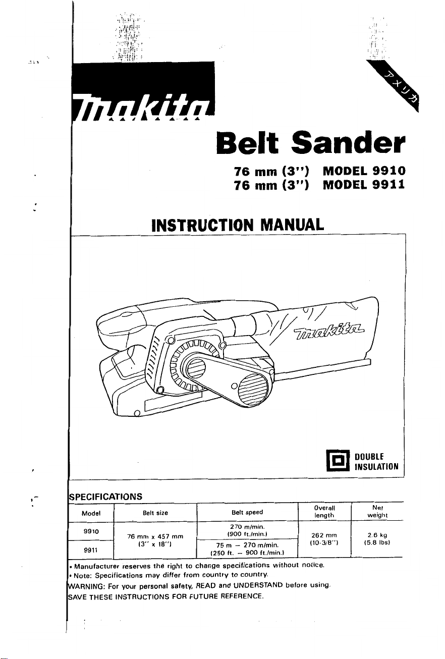
Sander
76
mm
(3”)
76
mm
(3”)
INSTRUCTION MANUAL
MODEL
MODEL
9910
9911
iPEClFlCATlONS
Model Belt size Belt speed
270
9910
9911
Manufacturer reserves the right to change specifications without notice.
Note: Specifications may differ from country to country.
4ARNING: For your personal safety, READ and UNDERSTAND before using.
AVE THESE INSTRUCTIONS FOR FUTURE REFERENCE.
76
mm
(3” x 18”)
x
457
mm
1250
mlmin.
1900 ft.lmin.1
75
m
-
270
ft. - 900 ft.lmin.1
mlmin.
Overall
length weight
262
110-318”)
mm
DOUBLE
INSULATION
Net
2
6
kg
15.8
Ibs)
GENERAL SAFETY RULES
(For
WARNING!
to follow
shock, fire and/or serious personal injury.
Read and understand all instructigns.
all
instructions listed below, may result
All
Tools)
Failure
in
electric
SAVE
READ
WORK AREA
1.
2.
3.
EL E CT
4.
5.
6.
7.
8.
PERSONAL SAFETY
9
10
ALL
Keep your work area clean and well
accidents.
Do
not operate power tools
of flammable liquids, gases, or dust. Power
ignite the dust
Keep bystanders, children, and visitors away while Operating a power tool.
Distractions can cause you to loose control.
R I C
Double Insulated tools are equipped
than the other.) This
plug does not fit fully
contact a qualified electrician to install a polarized outlet.
the
wire grounded power cord and grounded power supply system.
Avoid body contact
and refrigerators. There is an increased risk
grounded.
Don't expose power tools to rain or wet conditions. Water entering a power
tool
Do not abuse the cord. Never use the cord to carry the tools or
from an outlet. Keep cord away from heat,
Replace damaged cords immediately. Damaged cords increase the risk
electric shock.
When operating a power tool outside, use an outdoor extension cord marked
"W-A"
of electric shock.
Stay alert, watch what you are doing and use common sense when operatiig
a power tool.
alcohol, or medication.
may result in serious personal injury.
Dress properly.
your hair, clothing, and gloves away from moving parts. Loose clothes, jewelry
or long hair can be caugh
A L SAFETY
pfug
will
or
THESE INSTRUCTIONS
INSTRUCTIONS.
lit.
Cluttered benches and dark areas invite
in
explosive atmospheres, such as
or
fumes.
plug
will fit
in
the outlet, reverse the plug. If
in
any way. Double insulation
with
grounded surfaces such as pipes, radiators, ranges
increase the risk
"W."
These cords are rated for outdoor use and reduce the risk
Do
not use tool while tired or under the influence of drugs,
Do
not wear loose clothing or jewelry. Contain long hair. Keep
of
electric shock.
A
moment of inattention while operating power
in
poving parts.
\,
with
in
a polarized outlet only one way.
tools
create sparks which may
a polarized
@I
eliminates the need
of
oil,
plug
(one blade is wider
it
electric shock if your body is
sharp edges or moving parts.
in
the presence
still does not
Do
not change
for
pull
If
the
fit,
the three
the
plug
of
tools
I
2
..
,.
..
.
.
...
.
I
.1
,
..
.::.::
i.!'
.
.
...
:
;>.y.q+,:
'.
2,
!,
.
..
..
..
..
,
..
.
....
.
..!
i:.
,
:
..
..
.
..:i:.
. .
..
.
_..
.
..
..
..
..
,
.
.
:i:
::*:i
:
.
..
;:.".
1.
Avoid accidental starting. Be sure switch is off before plugging
with
tools
your finger on the switch or plugging
in
tools
that have the switch
in.
Carrying
on invites accidents.
2.
Remove
a key that is left attached to a rotating part of the tool may result
adjusting
keys
or switches before turning the tool on. A wrench or
in
personal
injury.
3.
Do not overreach. Keep proper footing and balance at all times. Proper footing
and balance enables better control of the tool
&.
Use safety equipment. Always wear eye protection. Dust mask, non-skid
in
unexpected situations.
safety shoes, hard hat, or hearing protection must be used for appropriate
conditions.
)OL
USE AND CARE
5.
Use clamps or other practical way
to
secure and support the workpiece to
a stable platform. Holding the work by hand or against your body is unstable
and may lead to
5.
Do not force tool. Use the correct tool for your application. The correct tool
loss of
will do the job better and safer at the rate for which
7.
Do not use tool if switch does not turn
be controlled with the switch
8.
Disconnect the plug from the power source before making any adjustments,
control.
is
it
is designed.
it
on or off. Any tool that cannot
dangerous and must be repaired.
changing accessories, or storing the tool. Such preventive safety measures
reduce the risk of starting the tool accidentally.
D.
Store idle tools out of reach of children and other untrained persons.
are dangerous
b.
Maintain tools
in
the hands of untrained users.
with
care. Keep cutting tools sharp and clean. Properly
Tools
maintained tools, with sharp cutting edges are less likely to bind and are easier
to control.
.
Check for misalignment or binding of moving parts, breakage of parts, and
any other condition that may affect the tools operation. If damaged, have
the tool serviced before using. Many accidents are caused by poorly maintained tools.
I.
Use only accessories that are recommended by the manufacturer for
model. Accessories that may be suitable for one tool, may become hazardous
when used on another tool.
RVICE
I.
Tool
service must be performed only by qualified repair personnel. Service
or maintenance performed
by
unqualified personnel could result in a risk
injury.
.
When servicing a tool, use only identical replacement parts. Follow instruc-
in
tions
the Maintenance section of this manual. Use of unauthorized parts
or failure to follow Maintenance Instructions may create a risk of electric shock
or injury.
your
of
3
Specific Safety
1.
Hold tools by insulated gripping surfaces when performing an operation where
the cutting
"live" wire
operator.
2.
Hold
3.
Make sure the belt is not contacting the workpiece before the switch
turned on.
4.
Keep hands away from rotating parts.
5.
Do
not leave the tool
6.
This tool has not been waterproofed,
surface.
tool
may
will
make exposed metal parts
the tool firmly
contact hidden wiring
with
both hands.
running.
Operate the
Rules
or
its own cord. Contact
of
the tool "live" and shock the
tool
only when hand-held.
so
do not use water
on
the workpiece
SAVE THESE INSTRUCTIONS.
with
a
is
4
..

..
.....
....
..
.;
:i
...
.
:I.?.
.
..,!!!.:
....
.....
...
'.
.A!,.!.'
.......
,
.
,
.-,
....
.
-
;:,;.:
::
.'.!.
.........
...
::.:
.:
....
::.
:i:.
:.
:..f
!.
,
:
.
.
SYMBOLS
The followings show the symbols used for
...........
amperes
.......................
.................................
.................................
.................................
......................
..................
....................
.................
...................
kilograms
hours
minutes
.
seconds
alternating current
..
direct current
....
no load speed
alternating or direct current
Class
II
Construction
......
splash-proof construction
..
watertight construction
tool.
ciprocation per minute

ASSEMBLY
Installing or removing abrasive belt
CAUTION:
Always be sure that the tool is switched off and unplugged before installing or removing
the belt.
Pull the lever all the way out and install the
belt over the rollers, then return the lever
the original position.
to
I
CAUTION:
When installing the belt, make sure that the
direction of the arrow on the back
to
belt corresponds
itself.
Adjusting belt tracking
Switch on the tool and make sure that the
belt is aligned properly.
belt extends beyond the edge of the steel
plate or the edge of the belt retracts more
8
mm
than
the steel plate, use the adjusting screw to
adjust the belt tracking.
(5/16")
the one on the tool
If
the edge of the
away from the edge of
of
the
I
Steel
I
7
I
plate
more
than
8
mm
(Y16")
k
6

..
.
..
.
.
...
.
. ..
.
.
.it::
:;.;
!
,
:.::;.p:
..
_._
.
.l:.
.
..
.,,:,.
.
..
...
.
,
..
.
....
.
._.,:
~
. . ...
..
.
.
.1.
.
.
.
..
..
.:..
.
..
..,
.
:::.:::I
.
.
,
::.-
US~
bag
ttach the dust bag onto the dust spout.
I
Dust
spout
ie dust spout is tapered. When attaching
e
dust bag, push it onto the dust spout
mly as far as it will go to prevent
it
from
ming off during operation.
)r
the best results, empty the dust bag
hen it becomes about half full. tapping
it
lhtfy to remove as much dust as possible.
Dusl
bag
PERATION
witch action
WTION:
3efore plugging in the tool, always check
ind returns to the
"OFF"
position when released.
-he tool should not be in contact with the workpiece surface when you turn the tool
)r off. Otherwise a poor sanding finish
to
see that the switch trigger actuates properly
or
damage of the belt may result.
on
,
start the tool, simply pull the trigger.
?lease the trigger to stop.
For
continuous
Cock
button
,eration, pull the trigger and then push in
e lock button. To stop the tool from the
:ked position, pull the trigger fully, then
lease it.
inding operation
Ad the tool firmly with both hands. Turn the tool on and wait until it attains full speed.
tool
ien gently place the
on the workpiece surface. Keep the belt flush with the work-
xe at all times and move the tool back and forth. Never force the tool. The weight of the
01
applies adequate pressure. Excessive pressure may cause stalling, overheating of the
otor, burning of the workpiece and possible kickback.

Speed adjusting dial
For
9911
only
The belt speed can be infinitely adjusted
between
turning the speed adjusting dial
number setting from
75
m
and
270
m
1
to
6.
Higher speed is
per minute
to
a
given
by
obtained when the dial is turned in the
direction
of
number
6;
lower speed
is
ob-
tained when it is turned in the direction of
number
1.
Select the proper speed for the workpiece
to be sanded.
Speed adjusting dial
'\
CAUTION:
The speed adjusting dial can be turned only as
or
1,
or the speed adjusting function may not longer work.
far
as 6 and back to
1.
Do
not force
it
past
6
..7!.5
.. . .-
,.
.
&.<,?
..,-.
..
...
.
.
.
..
.
.,
.'i'l.::.
.
,
:
.
::a>.:.::
,:.:*.:,
. I ..
.,.:.it
..
.
.. ..
...
..
z;;
...
-.....
.
.
..
.
<..
....
'
,
...
.:
:.
..
,
::.
..
.
.
.
.

MI
ON:
CA
j
be sure that the tool is switched
Alv
tion or maintenance.
ins1
:ing
carbon
Rei
re and check the carbon brushes reg-
Rei
Replace when they wear down to
ular
lit
the
clei
car1
sar
bru
Fir:
usc
hol
bru
the
mark. Keep the carbon brushes
ind free to slip in the holders. Both
brushes should be replaced at the
time.
S.
emove the belt cover from the tool.
screwdriver to remove the brush
caps. Take out the worn carbon
s,
insert the new ones and secure
ish holder caps.
brushes
Use
only identical carbon
off
and unplugged before attempting to perform
Limit
mark
Brush
holder
I
cap
\
ntain product SAFETY and RELIABILITY, repairs, any other maintenance or adjust-
To
hould be performed by Makita Authorized or Factory Service Centers, always using
me
replacement parts.
Ma
9

..
.
4
ACCESSORIES
CAUTION:
These accessories or attachments are recommended for use with your Makita tool specified
manual. The use
The accessories or attachments should be used only in the proper and intended manner.
*Abrasive belts
'Belt
type
AA
-
For wood, iron and steel.
Grit Sheets per pack
M60
AA240
of
any other accessories or attachments might present a risk
*Clamp
and use
Coarse
Medium
10
Fine
(2
I
pcs.)
of
injury
to
in
this
persons.

76
mm
BELT
Model
(3")
SANDER
9910
62
Note:
The
switch and other part configurations
may differ from country to country.
11

MODEL
'LtM
IO
I1
12
13
I4
15
16
I?
I0
19
20
21
22
23
24
25
26
27
20
29
30
31
32
~
..
9910
ED
DESCRIPTION
33
40
41
42
43
44
45
46
4?
48
49
50
51
52
53
54
55
56
57
50
59
60
61
62
83
34
35
36
31
30
39
I
4
1
I
I
I
I
I
I
I
1
1
1
I
1
I
7
1
2
I
1
I
1
1
I
I
I
I
I
I
I
1
1
2
4
I
3
I
4
I
5
6
I
I
1
0
I
9
1
1
1
1
I
1
2
I
2
I
I
I
1
1
I
1
2
2
2
1
I
I
I
I
-

76
mm
BELT
Model
(3")
SANDER
9911
Jan
-20-'98
US
62
Note: The switch and other part configurations
may differ from country to COUntrY.
13
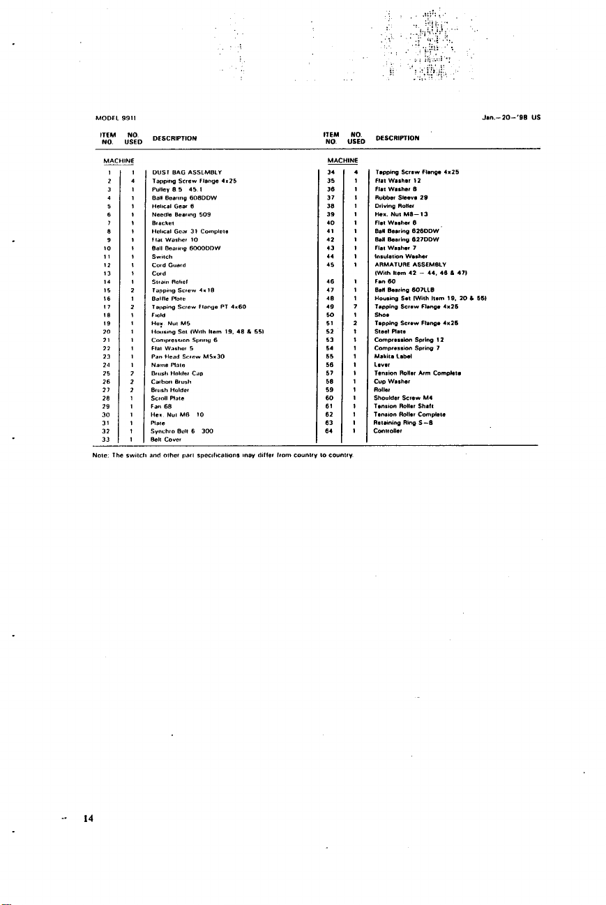
MODEL
ITEM
NO
9911
NO
USED
DESCRIPTIDN
Jan.-ZD-'90
I:","
$$
DESCRIPTION
US
10
II
I2
13
14
15
16
I7
I8
19
in
21
22
23
24
25
26
27
28
29
30
31
32
33
I
1
4
2
3
I
4
1
I
5
6
I
7
I
1
8
I
9
1
I
I
1
I
2
1
2
I
1
I
I
1
I
I
7
2
2
I
I
1
I
1
I
-
34
4
35
1
36
I
37
I
38
1
39
I
40
I
I1
I
41
I
43
1
14
I
45
1
46
I
47 1
40
1
49
7
MI
51
2
52
I
53 1
54
I
66
1
56
I
51
I
56
1
59
1
601
61
I
62
I
63
I
64
1

MAKITA
Every Makita tool is tliorou ily ins ected and tested before leaving the factory.
be free of defects lrom wor&lmanshrp and materials
original purchase. Should any trouble develop during this one-year period. return the COMPLETE
tool, freight prepaid.
the trouble is caused by delective workmanship
replace) without charge.
This Warranty does
repairs have been made
repairs 8re required because
The
tool
has been abused, misused
alterations have been made
IN NO EVENT SllALL MAKITA BE LIABLE FOR ANY INDIRECT. INCIDENTAL
SEQUENTIAL DAMAGES FROM THE SALE
APPLIES BOT11 DURING AND AFTER TIiE TERM OF THIS WARRANTY.
MAKITA DISCLAIMS LIABILITY
WARRANTIES OF “MERCIiANTABILITY” AND “FITNESS
AFTER THE ONE-YEAR TERM
This Warranty gives you specific legal rights, and you may also have other rights which vary lrom
state to state. Some states do not allow the exclusion
damages,
so
limitation on how long an implied warranty lasts.
the above limitation
LIMITED
to
one
of
not
apply where:
or
attempted by others:
of
to
ONE
YEAR WARRANTY
Warranty
Makita’s Factory
normal wea~ and tear:
or
improperly maintained;
the
tool.
FOR
OF
THIS WARRANTY.
or
exclusion may not apply to you. Some states do not allow
Policy
It
lor
the period
of
ONE YEAR lrom the date
or
Authorized Senice Centers.
or
material. Makita will repair
OR
USE OF THE PRODUCT. THIS DISCLAIMER
ANY IMPLIED WARRANTIES, INCLUDING IMPLIED
so
the above limitation may not apply to you.
or
limitation
FOR
A SPECIFIC PURPOSE.”
of
incidental
is warranted lo
If
inspection show
(or
at
or
consequential
our
OR
option,
CON-
1
I
01
Makita
3-1
1-8,
Sumiyoshi-cho,
Anjo,
Aichi
Corporation
446-8502
884138-069
Japan
PRINTED IN JAPAN
1998-
2
-
N
 Loading...