

Page 1
INSTRUCTION MANUAL
MANUEL D'INSTRUCTION
MANUAL DE INSTRUCCIONES
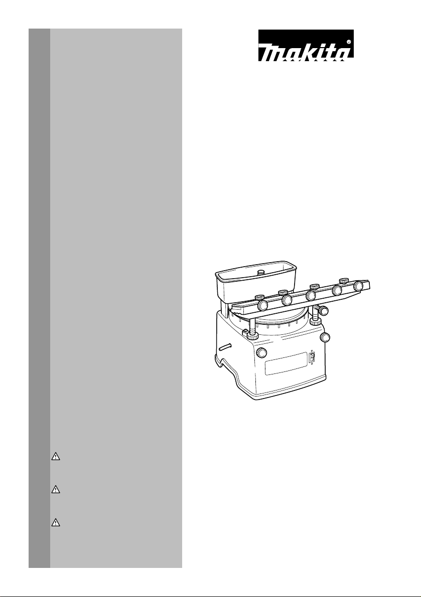
Sharpener
Affuteuse de delames
Afilador
9820-2
007269
WARNING:
For your personal safety, READ and UNDERSTAND before using.
SAVE THESE INSTRUCTIONS FOR FUTURE REFERENCE.
AVERTISSEMENT:
Pour votre propre sécurité, prière de lire attentivement avant l'utilisation.
GARDER CES INSTRUCTIONS POUR RÉFÉRENCE ULTÉRIEURE.
ADVERTENCIA:
Para su seguridad personal, LEA DETENIDAMENTE este manual antes de usar la
herramienta.
GUARDE ESTAS INSTRUCCIONES PARA FUTURA REFERENCIA.
1
Page 2

ENGLISH
SPECIFICATIONS
Model 9820-2
Wheel size 200 mm x 25 mm x 75 mm (7-7/8" x 1" x 3")
No load speed (RPM) 560 /min.
Overall length 390 mm (15-3/8")
• Due to our continuing programme of research and development, the specifications herein are subject to change without notice.
• Note: Specifications may differ from country to country.
For Your Own Safety Read
Instruction Manual
Before Operating Tool
Save it for future reference
GENERAL SAFETY
PRECAUTIONS
(For All Tools)
1. KNOW YOUR POWER TOOL. Read the owner's
manual carefully. Learn the tool's applications
and limitations, as well as the specific
potential hazards peculiar to it.
2. KEEP GUARDS IN PLACE and in working
order.
3. REMOVE ADJUSTING KEYS AND WRENCHES.
Form habit of checking to see that keys and
adjusting wrenches are removed from tool
before turning it on.
4. KEEP WORK AREA CLEAN. Cluttered areas
and benches invite accidents.
5. DO NOT USE IN DANGEROUS ENVIRONMENT.
Do not use power tools in damp or wet
locations, or expose them to rain. Keep work
area well lighted. Do not use tool in presence
of flammable liquids or gases.
6. KEEP CHILDREN AWAY. All visitors should be
kept safe distance from work area.
7. MAKE WORKSHOP KID PROOF with padlocks,
master switches, or by removing starter keys.
8. DO NOT FORCE TOOL. It will do the job better
and safer at the rate for which it was designed.
9. USE RIGHT TOOL. Do not force tool or
attachment to do a job for which it was not
designed.
Net weight 11 kg (24.3 lbs)
USA016-2
10. WEAR PROPER APPAREL. Do not wear loose
clothing, gloves, neckties, rings, bracelets, or
other jewelry which may get caught in moving
parts. Nonslip footwear is recommended.
Wear protective hair covering to contain long
hair.
11. ALWAYS USE SAFETY GLASSES. Also use
face or dust mask if cutting operation is dusty.
Everyday eyeglasses only have impact
resistant lenses, they are NOT safety glasses.
12. SECURE WORK. Use clamps or a vise to hold
work when practical. It's safer than using your
hand and it frees both hands to operate tool.
13. DO NOT OVERREACH. Keep proper footing
and balance at all times.
14. MAINTAIN TOOLS WITH CARE. Keep tools
sharp and clean for best and safest
performance. Follow instructions for
lubricating and changing accessories.
15. DISCONNECT TOOLS before servicing; when
changing accessories such as blades, bits,
cutters, and the like.
16. REDUCE THE RISK OF UNINTENTIONAL
STARTING. Make sure switch is in off position
before plugging in.
17. USE RECOMMENDED ACCESSORIES.
Consult the owner's manual for recommended
accessories. The use of improper accessories
may cause risk of injury to persons.
18. NEVER STAND ON TOOL. Serious injury could
occur if the tool is tipped or if the cutting tool
is unintentionally contacted.
19. CHECK DAMAGED PARTS. Before further use
of the tool, a guard or other part that is
damaged should be carefully checked to
determine that it will operate properly and
perform its intended function - check for
alignment of moving parts, binding of moving
parts, breakage of parts, mounting, and any
other conditions that may affect its operation.
A guard or other part that is damaged should
be properly repaired or replaced.
2
Page 3
20. DIRECTION OF FEED. Feed work into a blade
or cutter against the direction of rotation of the
blade or cutter only.
21. NEVER LEAVE TOOL RUNNING UNATTENDED.
TURN POWER OFF. Do not leave tool until it
comes to a complete stop.
22. REPLACEMENT PARTS. When servicing, use
only identical replacement parts.
VOLTAGE WARNING: Before connecting the tool to a
power source (receptacle, outlet, etc.) be sure the
voltage supplied is the same as that specified on the
nameplate of the tool. A power source with voltage
greater than that specified for the tool can result in
SERIOUS INJURY to the user- as well as damage to
the appliance. If in doubt, DO NOT PLUG IN THE
APPLIANCE. Using a power source with voltage less
than the nameplate rating is harmful to the motor.
USE PROPER EXTENSION CORD. Use only
three-wire extension cords that have three-prong
grounding-type plugs and three-pole receptacles
that accept the tool’s plug. Make sure your extension
cord is in good condition. Replace or repair
damaged or worn cord immediately. When using an
extension cord, be sure to use one heavy enough to
carry the current your product will draw. An
undersized cord will cause a drop in line voltage
resulting in loss of power and overheating. Table 1
shows the correct size to use depending on cord
length and nameplate ampere rating. If in doubt, use
the next heavier gage. The smaller the gage number,
the heavier the cord.
Table 1: Minimum gage for cord
Ampere Rating
Volts Total length of cord in feet
120 V 25 ft. 50 ft. 100 ft. 150 ft.
More Than Not More Than AWG
0 6 18 16 16 14
18 16 14 12610
10 12 16 16 14 12
000173
GROUNDING INSTRUCTIONS:
In the event of a malfunction or breakdown,
grounding provides a path of least resistance for
electric current to reduce the risk of electric shock.
This tool is equipped with an electric cord having an
equipment-grounding conductor and a grounding
plug.
The plug must be plugged into a matching outlet that
is properly installed and grounded in accordance
with all local codes and ordinances.
Do not modify the plug provided - if it will not fit the
outlet, have the proper outlet installed by a qualified
electrician.
Improper connection of the equipment-grounding
conductor can result in a risk of electric shock. The
conductor with insulation having an outer surface
that is green with or without yellow stripes is the
equipment-grounding conductor. If repair or
replacement of the electric cord or plug is necessary,
do not connect the equipment-grounding conductor
to a live terminal.
Check with a qualified electrician or service
personnel if the grounding instructions are not
completely understood, or if in doubt as to whether
the tool is properly grounded.
12 16 14 12
Repair or replace damaged or worn cord
immediately.
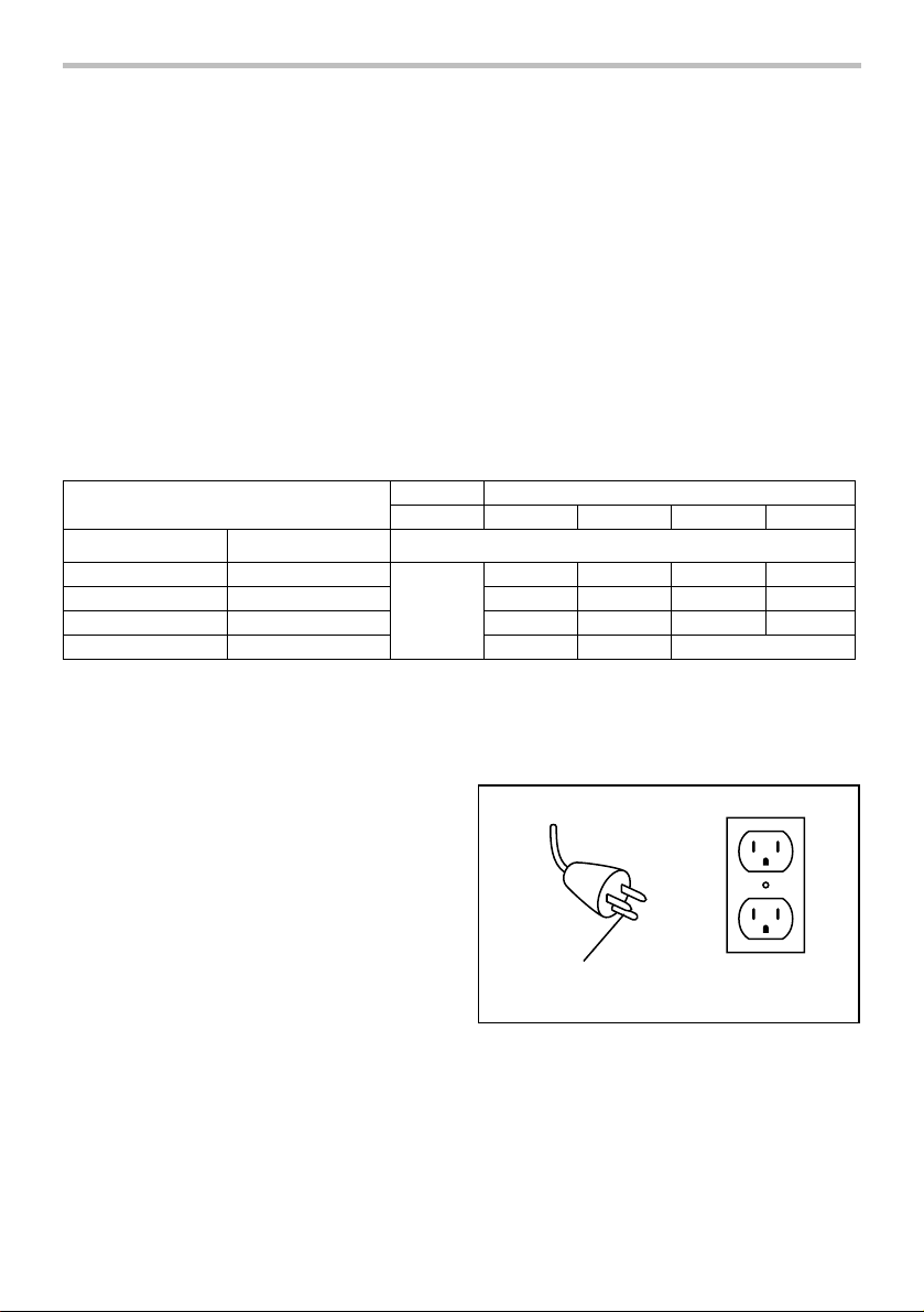
Your unit is for use on 120 volts and has a plug that
looks like Fig. “A”.
Fig. A
Grounding
000088
SPECIFIC SAFETY RULES
DO NOT let comfort or familiarity with product
(gained from repeated use) replace strict adherence
to sharpener safety rules. If you use this tool
unsafely or incorrectly, you can suffer serious
personal injury.
3
Blade
Not Recommended
Cover of Grounded
Outlet Box
USB089-1
Page 4
1. Wear eye protection.
2. Always use guards and eye shields.
3. Use only wheels having a maximum operating
speed at least as high as "No Load RPM"
marked on the tool's nameplate.
4. Check the wheel carefully for cracks or
damage before operation. Replace cracked or
damaged wheel immediately.
5. Secure the wheel carefully.
6. Be careful not to damage the spindle or the
bolt, or the wheel itself might break.
7. Keep a space of 5 mm (3/16") between the
sharpening platform guide (rail) and the
grinding wheel.
8. Keep hands away from rotating parts.
9. Make sure the workpiece is not contacting the
wheel before the switch is turned on.
10. Before using the tool on an actual workpiece,
let it run for several minutes. Watch for flutter
that might be caused by incorrect installation
or a poorly balanced wheel.
11. Use the upper surface of the wheel only. Do
not use the side surface.
12. If the wheel stops during operation, makes an
odd noise or begins to vibrate, switch off the
tool immediately.
13. Always switch off and wait for the wheel to
come to a complete stop before adjustment or
inspection.
14. Do not touch the workpiece immediately after
operation; it may be extremely hot and could
burn your skin.
15. Dry the wheel by idling the tool after operation
to prevent the wheel from freezing in cold
weather. Freezing can crack the wheel.
16. Store wheels in a dry location only.
17. Do not overtighten wheel nut.
18. Use only flanges furnished with this tool.
SAVE THESE INSTRUCTIONS.
WARNING:
MISUSE or failure to follow the safety rules stated in
this instruction manual may cause serious personal
injury.
FUNCTIONAL DESCRIPTION
CAUTION:
• Always be sure that the tool is switched off and
unplugged before adjusting or checking function on
the tool.
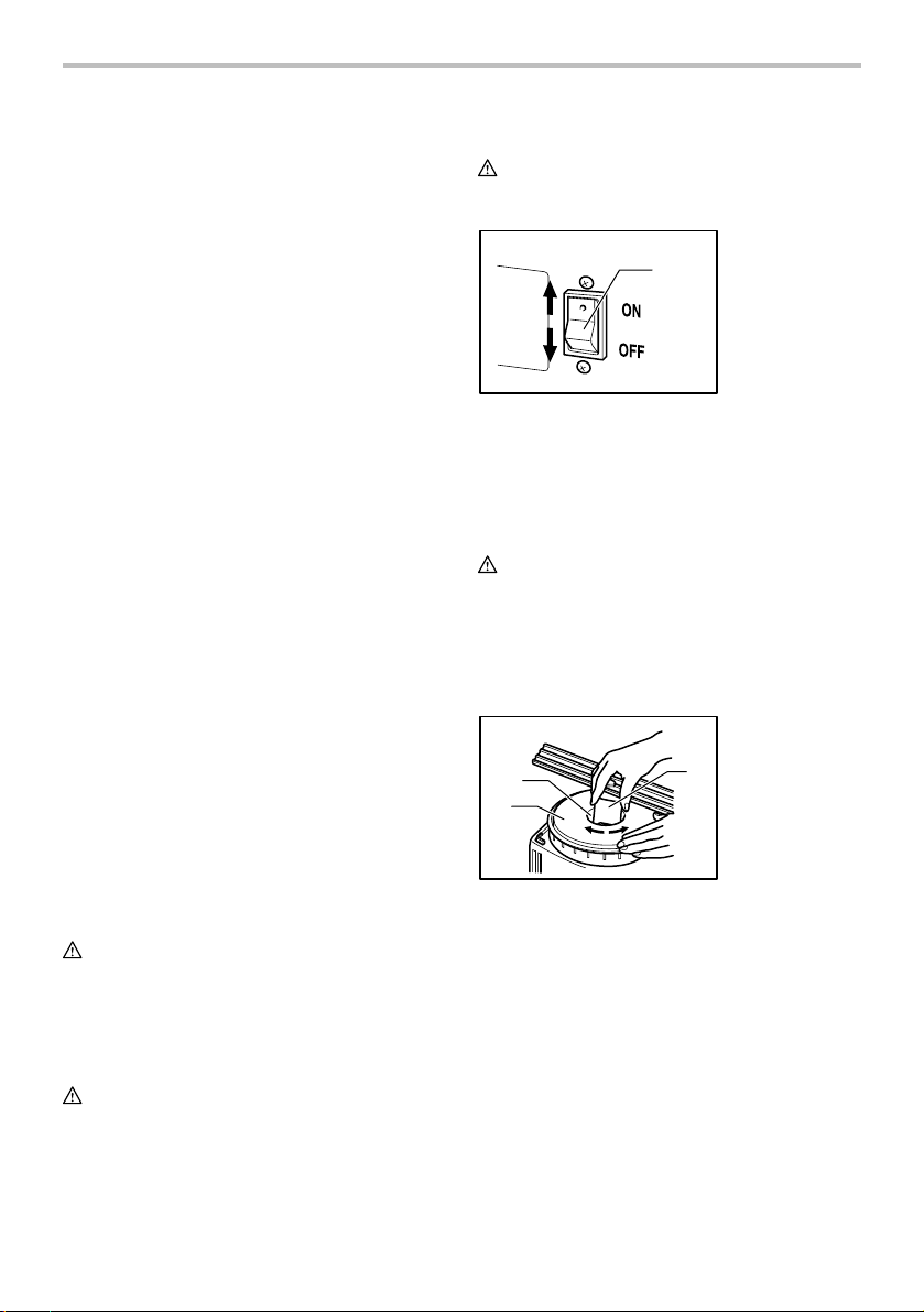
Switch action
CAUTION:
• Before plugging in the tool, always check to see
that the tool is switched off.
1. Switch
1
007285
To start the tool, press the "ON" side of the switch
located on the front of the tool. To stop the tool, press the
"OFF" side of the switch.
ASSEMBLY
CAUTION:
• Always be sure that the tool is switched off and
unplugged before carrying out any work on the
tool.
Replacing grinding wheel
Use the wrench provided to release the grinding wheel
by turning the installation screw counterclockwise.
1. Wrench
2. Grinding wheel
installation
2
3
007270
To install the grinding wheel, follow the removal
procedure in reverse.
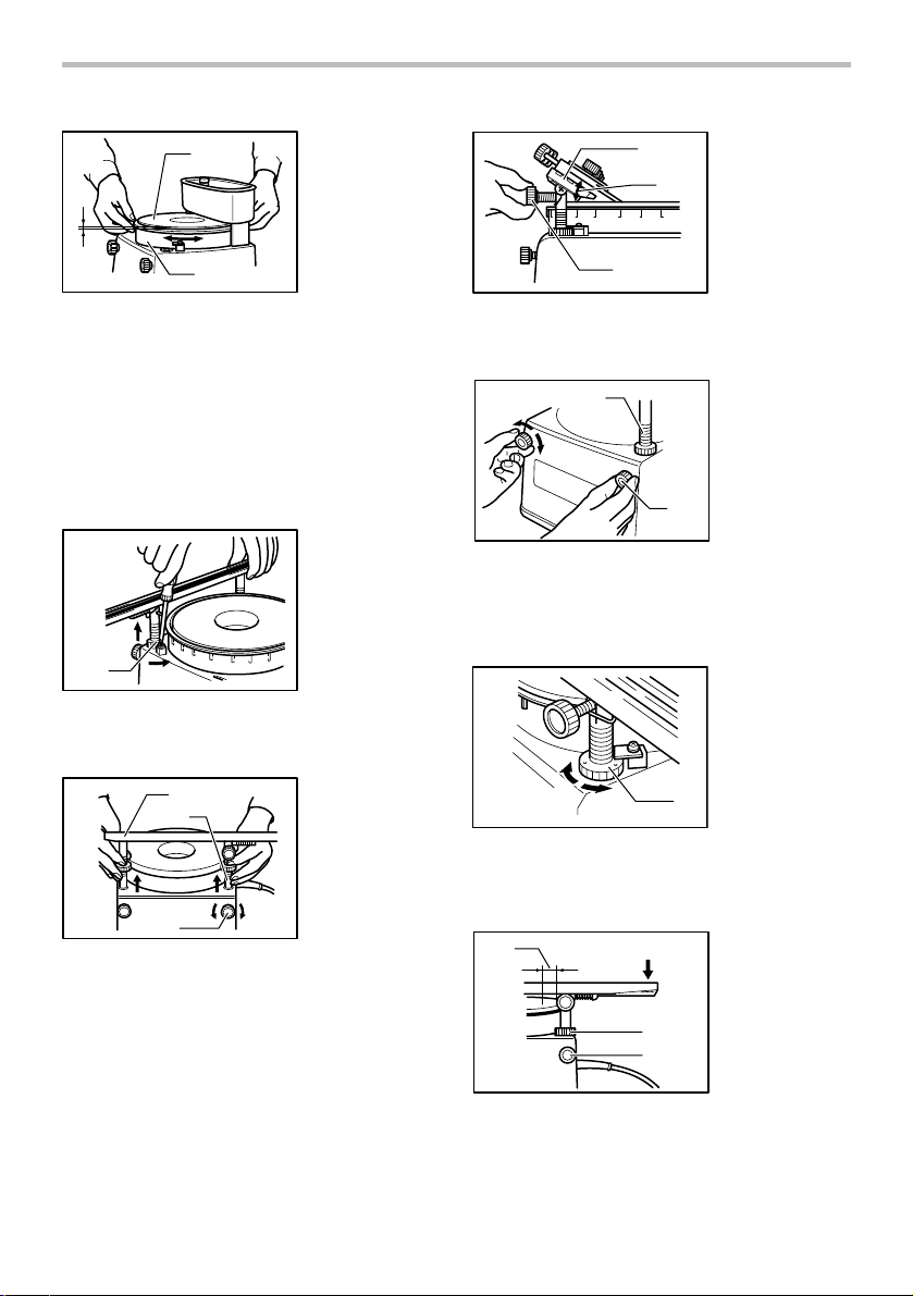
Adjusting wheel guard
The top of the wheel guard should be 1 mm (approx.
3/64") below the surface of the grinding wheel. Adjust
height by turning the guard clockwise to lower it, or
counterclockwise to raise it.
1
screw
3. Wheel
4
Page 5
1. Grinding wheel
2. Wheel guard
3. Lower
4. Raise
1mm
(3/64")
007271
1
3
4
2
Wiping off the antirust
Wipe off the antirust on the sharpening platform guide
(rail) and the sharpening holder. Coat the sharpening
platform guide and the sharpening holder with machine
oil or spindle oil.
Removing or installing sharpening platform
guide
To remove the sharpening platform guide, loosen the
screw and slip the set plate aside.
1. Slip aside
2. Set plate
1
2
007272
Loosen the pole fastening screws counterclockwise and
lift off the sharpening platform guide.
1
2
007273
To install the sharpening platform guide, follow the
removal procedure in reverse.
3
1. Sharpening
platform guide
(Rail)
2. Pole
3. Pole fastening
screw
Adjusting sharpening platform guide
In using the sharpening platform guide to sharpen
blade/knife, adjust the angle adjustment screw to the
desired blade/knife sharpening angle. The bevel
becomes acute as the angle adjustment screw is turned
clockwise.
1
3
007274
The platform poles are fixed in place by tightening the
pole fastening screws clockwise.
1
007275
The nut for raising or lowering the pole on either side raises the
pole 0.5 mm (1/32") for each graduation, when turned
clockwise, and it lowers the pole, conversely, 0.5 mm (1/32")
when turned counterclockwise.
1
0.5mm
(1/32")
007276
Tilt the sharpening platform guide slightly with right side
downward so that the blade contacts the right side
surface of the grinding wheel.
1
007277
2
2
3
4
1. Sharpening
platform guide
2
(Rail)
2. Blade/knife
sharpening
angle
3. Angle
adjustment
screw
1. Pole
2. Pole fastening
screw
2
1. Raising
2. Lowering
3. Graduation
3
1. Sharpen here
2. Tilt slightly
downward
3. Sharpening
guide vertical
adjustment nut
4. Pole fastening
screw
5
Page 6
Adjusting sharpening holder
The sharpening holder horizontal (forward) adjust
screws should be unscrewed to allow the heel of the
blade to be inserted so as to contact the blade fastening
screws. Then lightly tighten the blade fastening screws
and set the holder on the platform.
1. Blade fastening
screw
1
23
007278
Screw in clockwise the forward adjust screw on the right
until the right upper edge of the blade comes into contact
with the grinding wheel. Then fully tighten the fastening
screw on the far right.
2
007279
Slide the holder to the right across the sharpening
platform guide. Screw in the left-hand forward adjust
screw until the left upper edge of the blade contacts the
grinding wheel. Now use all four fastening screws to
secure the blade on the horizontal.
1
4
3
007280
2. Planer blade
3. Forward adjust
screw
1. Wheel
1
2. Right-hand
4
3
(forward) adjust
screw
3. Right-hand
fastening screw
4. Planer blade
1. Wheel
2. Left-hand
fastening screw
3. Left-hand
2
(forward) adjust
screw
4. Planer blade
Installing coolant reservoir (Tank)
Insert the reservoir legs into the grooves provided for
them on the sharpener frame.
1. Coolant
reservoir (Tank)
2. Grooves
1
2
007281
Adjusting coolant flow
Put water in the coolant reservoir. Turn the knob so that
the marking is positioned vertically to make the coolant
flow.
1
4
007282
Turn the marking to the horizontal position to stop the
coolant flow.
1
4
007283
NOTE:
• Adjust the coolant flow adequately. If the debris
from the grinding wheel and the blade is washed
away by the coolant, the coolant flow is excessive.
2
3
2
3
1. Coolant
reservoir (Tank)
2. Knob
3. Water
4. Marking
1. Coolant
reservoir (Tank)
2. Knob
3. Water
4. Marking
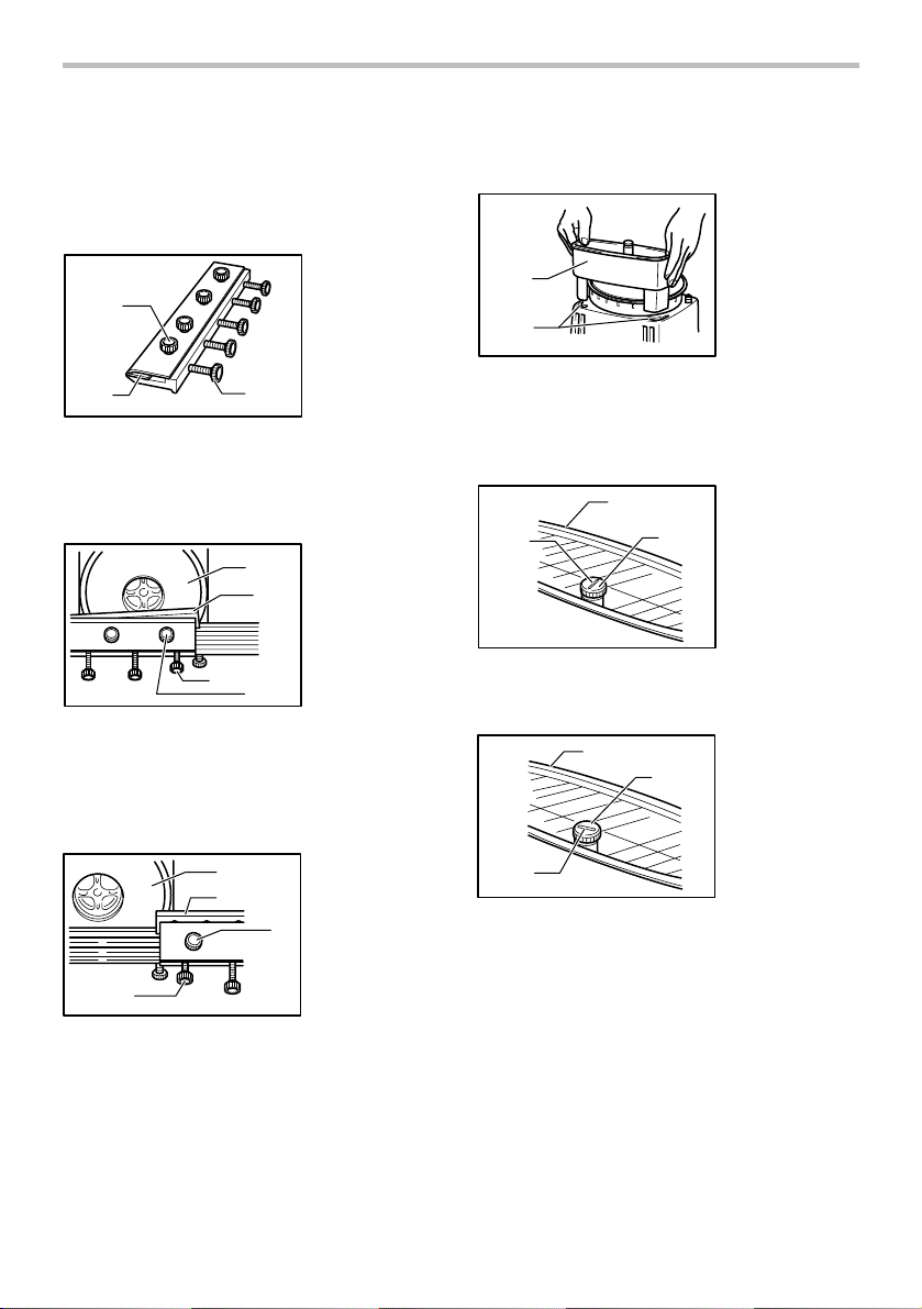
Draining used coolant
The used coolant drains out through the drain hose
(vinyl tube) provided. Have a pan or drain system ready
to catch it.
6
Page 7
1. Drain hose
(Vinyl tube)
1
Sharpening power planer blades
Sharpen your planer blades to 40° angle.
1. Approx. 40 ゚
2. Planer blade
1
007284
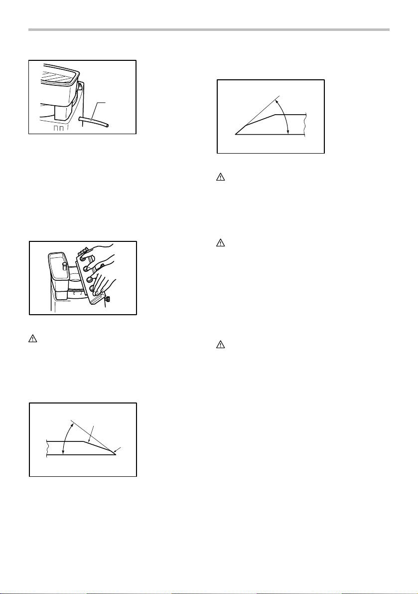
OPERATION
Sharpening blade/knife
After you have established the correct coolant flow, you
can begin sharpening. Sharpen with the cutting edge
away from you, holding the sharpening holder with both
hands. Slide the sharpening holder back and forth on the
sharpening platform guide at a speed of about ten times
per minute, applying uniform pressure (about 5 kg (11
lbs)) on it.
007286
CAUTION:
• Always use sharpening platform guide or guide
assembly (optional accessory) when sharpening
blade/knife.
Remove some stock from the tip to the heel in relation to
the original grinding angle so as to create a better cutting
edge.
2
1
007287
1. Original (proper)
grinding angle
2. Take down this
area slightly in
relation to
3
original angle
3. Tip (correct
sharpening
angle)
2
007288
CAUTION:
• Clean and dry the tool after operation.
• Be sure that the tool is switched off, unplugged and
drained before attempting to move the tool.
MAINTENANCE
CAUTION:
• Always be sure that the tool is switched off and
unplugged before attempting to perform inspection
or maintenance.
To maintain product SAFETY and RELIABILITY, repairs,
any other maintenance or adjustment should be
performed by Makita Authorized or Factory Service
Centers, always using Makita replacement parts.
ACCESSORIES
CAUTION:
• These accessories or attachments are
recommended for use with your Makita tool
specified in this manual. The use of any other
accessories or attachments might present a risk of
injury to persons. Only use accessory or
attachment for its stated purpose.
If you need any assistance for more details regarding
these accessories, ask your local Makita Service Center.
• Grinding wheels (#60, #1000, #6000)
• Wrench
• Guide assembly (sharpening platform guide)
7
Page 8

MAKITA LIMITED ONE YEAR WARRANTY
Warranty Policy
Every Makita tool is thoroughly inspected and tested
before leaving the factory. It is warranted to be free of
defects from workmanship and materials for the period
of ONE YEAR from the date of original purchase.
Should any trouble develop during this one year period,
return the COMPLETE tool, freight prepaid, to one of
Makita’s Factory or Authorized Service Centers. If
inspection shows the trouble is caused by defective
workmanship or material, Makita will repair (or at our
option, replace) without charge.
This Warranty does not apply where:
repairs have been made or attempted by others:
repairs are required because of normal wear and
tear:
the tool has been abused, misused or improperly
maintained:
alterations have been made to the tool.
IN NO EVENT SHALL MAKITA BE LIABLE FOR ANY
INDIRECT, INCIDENTAL OR CONSEQUENTIAL
DAMAGES FROM THE SALE OR USE OF THE
PRODUCT. THIS DISCLAIMER APPLIES BOTH
DURING AND AFTER THE TERM OF THIS
WARRANTY.
MAKITA DISCLAIMS LIABILITY FOR ANY IMPLIED
WARRANTIES, INCLUDING IMPLIED WARRANTIES
OF "MERCHANTABILITY" AND "FITNESS FOR A
SPECIFIC PURPOSE," AFTER THE ONE YEAR TERM
OF THIS WARRANTY.
This Warranty gives you specific legal rights, and you
may also have other rights which vary from state to
state. Some states do not allow the exclusion or
limitation of incidental or consequential damages, so
the above limitation or exclusion may not apply to you.
Some states do not allow limitation on how long an
implied warranty lasts, so the above limitation may not
apply to you.
EN0006-1
8
Page 9

FRANÇAIS
SPÉCIFICATIONS
Modèle 9820-2
Taille de la meule 200 mm x 25 mm x 75 mm (7-7/8" x 1" x 3")
Vitesse à vide (T/MIN) 560 /min.
Longueur totale 390 mm (15-3/8")
Poids net 11 kg (24.3 lbs)
• Étant donné l'évolution constante de notre programme de recherche et de développement, les spécifications contenues dans ce
manuel sont sujettes à modification sans préavis.
• Note : Les spécifications peuvent varier suivant les pays.
Pour votre propre sécurité,
veuillez lire le manuel
d'instructions
Avant d'utiliser l'outil
Conservez-le pour référence
ultérieure
PRÉCAUTIONS GÉNÉRALES
(POUR TOUS LES OUTILS)
1. VOUS DEVEZ CONNAÎTRE VOTRE OUTIL
ÉLECTRIQUE. Lisez attentivement le manuel
d'instructions. Familiarisez-vous avec les
applications et limites de l'outil, ainsi qu'avec
les risques potentiels qui lui sont spécifiques.
2. MAINTENEZ LES PROTECTEURS EN PLACE
et en bon état de fonctionnement.
3. RETIREZ LES CLÉS DE RÉGLAGE ET DE
SERRAGE. Prenez l'habitude de vous assurer
que les clés de réglage et de serrage ont été
retirées de l'outil avant de le mettre sous
tension.
4. MAINTENEZ LA ZONE DE TRAVAIL PROPRE.
Les zones de travail et les établis encombrés
ouvrent grande la porte aux accidents.
5. ÉVITEZ L'UTILISATION DANS UN
ENVIRONNEMENT DANGEREUX. N'utilisez
pas les outils électriques dans les endroits
humides ou mouillés, et ne les exposez pas à
la pluie. Maintenez un éclairage adéquat dans
la zone de travail. Ne vous servez pas de votre
outil en présence de liquides ou gaz
inflammables.
USA016-2
6. MAINTENEZ LES ENFANTS À L'ÉCART. Toute
autre personne que l'utilisateur de l'outil doit
se tenir à une distance sûre de l'aire de travail.
7. FAITES EN SORTE QUE L'ATELIER SOIT
SANS DANGER POUR LES ENFANTS, en y
posant des cadenas, un interrupteur principal,
ou en retirant des équipements leurs clés de
démarrage.
8. NE FORCEZ PAS L'OUTIL. Il effectuera un
travail de meilleure qualité et plus sécuritaire
s'il est utilisé au régime pour lequel il a été
conçu.
9. UTILISEZ LE BON OUTIL. Ne forcez pas un
outil ou accessoire à effectuer un travail pour
lequel il n'a pas été conçu.
10. PORTEZ DES VÊTEMENTS ADÉQUATS. Ne
portez ni vêtements ni gants amples, ni
cravate, anneaux/bagues, bracelets ou autres
bijoux susceptibles d'être happés par les
pièces mobiles de l'outil. Le port de
chaussures antidérapantes est recommandé.
Portez un filet de protection pour envelopper
les cheveux longs.
11. PORTEZ TOUJOURS DES LUNETTES DE
SÉCURITÉ. Si le travail de coupe dégage de la
poussière, portez également un écran facial ou
un masque antipoussières. Les lunettes
ordinaires ne sont munies que de lentilles
résistances aux chocs ; elles ne constituent
PAS des lunettes de sécurité.
12. FIXEZ BIEN LA PIÈCE. Lorsque cela est
possible, fixez la pièce à travailler à l'aide de
dispositifs de serrage ou d'un étau. Cela est
plus sécuritaire que l'utilisation de la main et
libère les deux mains pour le maniement de
l'outil.
13. MAINTENEZ UNE BONNE POSITION.
Assurez-vous d'une bonne prise au sol et
d'une bonne position d'équilibre en tout
temps.
9
Page 10

14. PRENEZ SOIN DES OUTILS. Maintenez les
outils bien aiguisés et propres pour assurer
une performance sécuritaire et optimale.
Suivez les instructions de lubrification et de
changement des accessoires.
15. DÉBRANCHEZ LES OUTILS avant tout travail
de réparation ou avant de changer les
accessoires tels que lames,
embouts/forets/fraises et couteaux.
16. RÉDUISEZ LES RISQUES DE MISE EN
MARCHE ACCIDENTELLE. Assurez-vous que
l'interrupteur est en position d'arrêt avant de
brancher l'outil.
17. UTILISEZ LES ACCESSOIRES
RECOMMANDÉS. Consultez le manuel de
l'utilisateur pour savoir quels sont les
accessoires recommandés. L'utilisation
d'accessoires non adéquats peut comporter
un risque de blessure.
18. NE VOUS APPUYEZ JAMAIS SUR L'OUTIL.
Vous courez un risque de blessure grave si
l'outil bascule ou si vous touchez
accidentellement l'outil tranchant.
19. VÉRIFIEZ S'IL Y A DES PIÈCES
ENDOMMAGÉES. Avant d'utiliser l'outil, tout
protecteur ou dispositif endommagé doit être
vérifié soigneusement afin de s'assurer qu'il
fonctionne adéquatement et peut remplir la
fonction pour laquelle il est conçu. Vérifiez si
les pièces mobiles sont bien alignées et bien
fixées, vérifiez la présence de pièces brisées,
vérifiez que l'outil est bien monté et
assurez-vous que rien ne peut entraver son
bon fonctionnement. Un protecteur ou tout
autre dispositif endommagé doit être
adéquatement réparé ou remplacé.
20. SENS D'ALIMENTATION. Vous devez faire
avancer la pièce à l'encontre de la lame ou de
l'outil tranchant, non la faire progresser dans
le même sens.
21. NE LAISSEZ JAMAIS SANS SURVEILLANCE
22. PIÈCES DE RECHANGE. Seules des pièces de
MISE EN GARDE RELATIVE À LA TENSION : avant
de brancher l'outil sur une source d'alimentation
(prise ou autre dispositif), assurez-vous que la
tension du circuit correspond à celle qui est
spécifiée sur la plaque signalétique de l'outil.
L'utilisation d'une source d'alimentation dont la
tension est supérieure à celle spécifiée pour l'outil
peut entraîner une GRAVE BLESSURE et
endommager l'outil. En cas de doute, NE
BRANCHEZ PAS L'OUTIL. L'utilisation d'une source
d'alimentation dont la tension est inférieure à la
valeur indiquée sur la plaque signalétique
endommagera le moteur.
UTLISEZ UN CORDON PROLONGATEUR ADÉQUAT.
N'utilisez que les cordons prolongateurs à trois fils
et munis d'une fiche tripolaire, ainsi que des prises
tripolaires adaptées à la fiche de l'outil.
Assurez-vous que le cordon prolongateur est en bon
état. Remplacez ou réparez sans tarder tout cordon
endommagé ou usé. Lors de l'utilisation d'un cordon
prolongateur, utilisez sans faute un cordon assez
gros pour conduire le courant dont l'outil a besoin.
Un cordon trop petit provoquera une baisse de
tension de secteur, résultant en une perte de
puissance et une surchauffe. Le Tableau 1 indique la
dimension appropriée de cordon selon sa longueur
et selon l'intensité nominale indiquée sur la plaque
signalétique. En cas de doute sur un cordon donné,
utilisez le cordon suivant (plus gros). Plus le numéro
de gabarit indiqué est petit, plus le cordon est gros.
Tableau 1. Gabarit minimum du cordon
Intensit
é nominale
Volts Longueur totale du cordon en pieds
120 V 25 pi 50 pi 100 pi 150 pi
Plus de Pas plus de Calibre am
0 6 18 16 16 14
10 12 16 16 14 12
000173
12 16 14 12
10
UN OUTIL EN MARCHE. COUPEZ LE CONTACT.
Attendez que l'outil se soit complètement
arrêté avant de le quitter.
rechange identiques aux originales doivent
être utilisées lors des réparations.
éricain des fils
18 16 14 12610
Non recommand
é
Page 11

INSTRUCTIONS DE MISE À LA TERRE:
En cas de défaut de fonctionnement ou de panne, la
mise à la terre offre un circuit de résistance
inférieure pour le courant électrique afin de réduire
les risques d’électrocution. Cet outil est doté d’un
cordon d’alimentation muni d’un conducteur et
d’une fiche pour la mise à la terre de l’appareil.
La fiche doit être branchée dans une prise de
courant correspondante, installée correctement et
mise à la terre conformément à tous les codes et
ordonnances en vigueur.
Ne modifiez pas la fiche fournie - s’il est impossible
de la brancher dans la prise, demandez à un
électricien qualifié d’installer une prise adéquate.
Le branchement incorrect du conducteur servant à
la mise à la terre de l’appareil peut entraîner des
risques d’électrocution. Le conducteur présentant
une enveloppe isolante de couleur verte, avec ou
sans lignes jaunes, sert à la mise à la terre de
l’appareil. S’il est nécessaire de réparer ou de
remplacer le cordon ou la fiche d’alimentation, ne
branchez pas le conducteur de mise à la terre à une
borne sous tension.
Demandez à un électricien qualifié ou au personnel
de service si vous ne comprenez pas complètement
les instructions de mise à la terre, ou si vous êtes
incertain si l’outil est mis à la terre adéquatement.
Le cordon d’alimentation doit être réparé ou
remplacé immédiatement s’il est endommagé ou usé.
Votre appareil est conçu pour être alimenté par un
courant de 120 volts et sa fiche est illustrée à la Fig. «
A ».
Fig. A
Lame de mise à la terre
000088
Couvercle de la prise
d’alimentation mise à
la terre
USB089-1
RÈGLES DE SÉCURITÉ
PARTICULIÈRES
NE TOMBEZ PAS dans le piège de l'habitude et de la
facilité parce que vous avez beaucoup utilisé l'outil.
Respectez toujours les mesures de sécurité les plus
strictes en matière d'affûtage. Une utilisation
dangereuse ou incorrecte peut entraîner des
blessures importantes.
1. Portez un protecteur pour la vue.
2. Utilisez toujours des protecteurs corporels, y
compris pour les yeux.
3. N'utilisez que des meules dont la vitesse
maximale est égale ou supérieure à la valeur
de "Vitesse à vide (T/MIN)" indiquée sur la
plaque signalétique.
4. Avant l'utilisation, assurez-vous que la meule
ne présente ni fissure, ni défaut d'aucune
sorte. Le cas échéant, changez-la
immédiatement.
5. Fixez fermement la meule.
6. N'endommagez ni l'axe ni le boulon, car la
meule pourrait casser.
7. Gardez un espace de 5 mm (3/16 po) entre le
rail-guide de la plateforme d'affûtage et la
meule.
8. Gardez les mains éloignées des pièces en
rotation.
9. La pièce à travailler ne doit pas toucher la
meule avant le démarrage de l'outil.
10. Laissez l'outil fonctionner pendant quelques
minutes avant de travailler sur une pièce.
Attention aux vibrations causées par une
installation inadéquate ou une meule mal
équilibrée.
11. N'utilisez que la surface du dessus de la meule.
N'utilisez pas la surface latérale.
12. Si la meule s'arrête durant l'utilisation, émet
un bruit étrange ou se met à vibrer, arrêtez-la
immédiatement.
13. Avant de modifier un réglage ou de procéder à
une inspection, mettez toujours l'outil hors
tension et attendez l'arrêt complet de la meule.
14. Ne touchez pas la pièce immédiatement après
l'utilisation ; elle peut être très chaude et
brûler votre peau.
15. Séchez la meule en la faisant tourner au ralenti
après son utilisation. Ceci l'empêchera de
geler par temps froid. Le gel peut fissurer la
meule.
16. Rangez toujours les meules dans un endroit
sec.
17. Ne serrez pas l'écrou de la meule trop
fermement.
18. N'utilisez que les flasques fournies avec
l'outil.
CONSERVEZ CE MODE
D'EMPLOI.
11
Page 12

AVERTISSEMENT:
Une MAUVAISE UTILISATION de l'outil ou
l'ignorance des consignes de sécurité du présent
manuel d'instructions peuvent entraîner une grave
blessure.
DESCRIPTION DU
FONCTIONNEMENT
ATT EN TI ON :
• Assurez-vous toujours que l'outil est hors tension
et débranché avant de l'ajuster ou de vérifier son
fonctionnement.
Interrupteur
ATT EN TI ON :
• Avant de brancher l'outil, vérifiez toujours que
l'outil est hors tension.
1. Interrupteur
1
007285
Pour faire démarrer l'outil, appuyez du côté "ON" de
l'interrupteur situé à l'avant. Pour l'arrêter, appuyez du
côté "OFF" de l'interrupteur.
ASSEMBLAGE
ATT EN TI ON :
• Avant d'effectuer toute intervention sur l'outil,
assurez-vous toujours qu'il est hors tension et
débranché.
Remplacement de la meule
Utilisez la clé fournie avec l'outil et retirez la meule en
tournant la vis de maintien dans le sens inverse des
aiguilles d'une montre.
1. Clé
2. Vis de maintien
de la meule
2
3
007270
1
3. Meule
Suivez la procédure inverse pour installer une meule.
Réglage du carter de meule
Le dessus du carter de meule devrait être à 1 mm
(environ 3/64 po) de la surface de la meule. Réglez la
hauteur en tournant le carter dans le sens des aiguilles
d'une montre pour l'abaisser ou dans le sens inverse
pour le relever.
1. Meule
2. Carter de meule
3. Abaisser
4. Augmenter
1mm
(3/64")
007271
1
3
4
2
Nettoyage du contre-guide
Essuyez le contre-guide du côté du rail-guide de la
plateforme d'affûtage et du côté du support d'affûtage.
Enduisez le guide de la plateforme et le support
d'affûtage d'huile mouvement ou d'huile à broches.
Retrait et installation du guide de la
plateforme d'affûtage
Pour retirer le guide de la plateforme d'affûtage,
desserrez la vis et faites glisser la plaque de fixation
latéralement.
1. Glissement
latéral
2. Plaque de
fixation
1
2
007272
Desserrez les vis de fixation de la tige (dans le sens
inverse des aiguilles d'une montre) et dégagez le guide
de la plateforme d'affûtage.
1
2
3
007273
1. Rail-guide de la
plateforme
d’affûtage
2. Tige
3. Vis de fixation
de la tige
12
Page 13

Suivez la procédure inverse pour installer le guide de la
plateforme d'affûtage.
Réglage du guide de la plateforme d'affûtage
Lorsque vous utilisez le guide de la plateforme pour
affûter une lame ou un couteau, ajustez la vis de réglage
d'angle selon l'angle d'affûtage désiré. Pour obtenir un
biseau plus pointu, tournez la vis de réglage dans le
sens des aiguilles d'une montre.
1
3
007274
Pour serrer les tiges de la plateforme, tournez les vis de
fixation de tige dans le sens des aiguilles d'une montre.
1
007275
Chaque graduation de l'écrou d'élévation et
d'abaissement de la tige d'un côté ou de l'autre déplace
la tige de 0.5 mm (1/32 po), vers le haut quand on le
tourne dans le sens des aiguilles d'une montre, et vers
le bas en sens inverse.
1
0.5mm
(1/32")
007276
Inclinez légèrement le guide de la plateforme d'affûtage
(le côté droit vers le bas) jusqu'à ce que la lame touche
la surface de la meule.
2
1. Rail-guide de la
plateforme
2
d’affûtage
2. Angle d’affûtage
de la lame/du
couteau
3. Vis de réglage
d’angle
1. Tige
2. Vis de fixation
de la tige
2
1. Relever
2. Abaisser
3. Graduation
3
1. Affûter ici
2. Incliner
légèrement vers
le bas
Écrou de réglage
3.
vertical du guide
d’affûtage
4. Vis de fixation
de la tige
007277
1
2
3
4
Réglage du support d'affûtage
Dévissez les vis de réglage horizontal du support
d'affûtage (vers l'avant) pour déplacer le talon de la lame
afin qu'il touche les vis de fixation de la lame. Resserrez
ensuite légèrement les vis de fixation et installez le
support sur la plateforme.
1. Vis de fixation
de la lame
1
23
007278
Vissez dans le sens des aiguilles d'une montre la vis de
réglage vers l'avant qui se trouve du côté droit, jusqu'à
ce que le bord supérieur droit de la lame touche la
meule. Resserrez ensuite fermement la vis de fixation
du côté arrière droit.
2
007279
Faites glisser le support vers la droite en travers du
guide de la plateforme d'affûtage. Serrez la vis de
réglage pour gauchers (vers l'avant) jusqu'à ce que le
bord supérieur gauche de la lame touche la meule. Enfin,
fixez fermement la lame à l'horizontale en vous servant
des quatre vis de réglage.
2. Fer de rabot
3. Vis de réglage
vers l’avant
1. Meule
1
2. Vis de réglage
4
3
pour droitiers
(vers l’avant)
3. Vis de fixation
pour droitiers
4. Fer de rabot
13
Page 14

1
4
3
007280
1. Meule
2. Vis de fixation
pour gauchers
3. Vis de réglage
2
pour gauchers
(vers l’avant)
4. Fer de rabot
Installation du réservoir à liquide de
refroidissement
Insérez les pieds du réservoir dans les rainures prévues
à cet effet sur le châssis de l'affûteuse de lames.
1. Réservoir à
liquide de
refroidissement
1
2
007281
2. Rainures
Réglage du flux du liquide de refroidissement
Mettez de l'eau dans le réservoir du liquide de
refroidissement. Placez le repère en position verticale
en tournant le bouton pour permettre l'écoulement du
liquide.
1
4
2
3
1. Réservoir à
liquide de
refroidissement
2. Bouton
3. Eau
4. Repère
NOTE:
• Réglez le flux du liquide de refroidissement. Si le
liquide emporte les débris laissés par la meule et la
lame, c'est que le débit est excessif.
Vidange du liquide de refroidissement usé
Le tuyau de vidange (un tube en vinyle), fourni avec
l'outil, permet d'éliminer le liquide de refroidissement usé.
Utilisez un bac ou un système de vidange pour
récupérer le liquide qui s'échappera.
1. Tuyau de
vidange (tube en
vinyle)
1
007284
UTILISATION
Affûtage de lames et couteaux
Après avoir régler le débit d'écoulement du liquide de
refroidissement, vous pouvez commencer à vous servir
de l'outil. Affûtez les pièces en maintenant le côté
tranchant éloigné; tenez le support d'affûtage avec les
deux mains. Faites glisser le support d'affûtage sur le
guide de la plateforme dans un mouvement de
va-et-vient, à une vitesse d'environ 10 mouvements par
minute, et en appliquant une pression constante
d'environ 5 kg (11 lb).
007282
Tournez le repère en position horizontale pour bloquer
l'écoulement du liquide.
1
3
4
007283
1. Réservoir à
2
liquide de
refroidissement
2. Bouton
3. Eau
4. Repère
007286
ATT EN TI ON :
• Servez-vous toujours du guide de la plateforme
d'affûtage ou de l'ensemble de guidage (offert en
option) pour affûter des lames ou des couteaux.
Pour améliorer la qualité du tranchant, retirez les
fragments qui se déposent entre le bout et le talon, dans
l'angle d'affûtage initial.
14
Page 15

2
A
À
A
1
3
007287
Affûtage des fers de raboteuses
Aiguisez vos lames de raboteuses à un angle de 40°.
1
2
007288
ATT EN TI ON :
• Nettoyez et séchez l'outil après utilisation.
• Assurez-vous que l'outil est hors tension,
débranché et vidangé avant de le déplacer.
ENTRETIEN
ATT EN TI ON :
• Assurez-vous toujours que l'outil est hors tension
et débranché avant d'y effectuer tout travail
d'inspection ou d'entretien.
Pour maintenir la SÉCURITÉ et la FIABILITÉ du produit,
les réparations, tout autre travail d'entretien ou de
réglage doivent être effectués dans un centre de service
Makita agréé ou un centre de service de l'usine Makita,
exclusivement avec des pièces de rechange Makita.
ACCESSOIRES
ATT EN TI ON :
• Ces accessoires ou pièces complémentaires sont
recommandés pour l'utilisation avec l'outil Makita
spécifié dans ce mode d'emploi. L'utilisation de
tout autre accessoire ou pièce complémentaire
peut comporter un risque de blessure. N'utilisez les
accessoires ou pièces qu'aux fins auxquelles ils
ont été conçus.
1. Angle d’affûtage
initial (final)
2.
Abaissez cette
partie légèrement
par rapport à
l’angle initial.
3. Bout (angle
d’affûtage
adéquat)
1. Environ 40 ゚
2. Fer de rabot
Si vous désirez obtenir plus de détails concernant ces
accessoires, veuillez contacter le centre de service
après-vente Makita le plus près.
• Meules (nos 60, 1000, 6000)
• Clé
• Ensemble de guidage (guide de la plateforme
d'affûtage)
GARANTIE LIMITÉE D’UN AN MAKITA
Politique de garantie
Chaque outil Makita est inspecté rigoureusement et
testé avant sa sortie d’usine. Nous garantissons qu’il
sera exempt de défaut de fabrication et de vice de
matériau pour une période d’UN AN à partir de la date
de son achat initial. Si un problème quelconque devait
survenir au cours de cette période d’un an, veuillez
retourner l’outil COMPLET, port payé, à une usine ou à
un centre de service après-vente Makita. Makita
réparera l’outil gratuitement (ou le remplacera, à sa
discrétion) si un défaut de fabrication ou un vice de
matériau est découvert lors de l’inspection.
Cette garantie ne s’applique pas dans les cas où:
des réparations ont été effectuées ou tentées par
un tiers:
des réparations s’imposent suite à une usure
normale:
l’outil a été malmené, mal utilisé ou mal entretenu:
l’outil a subi des modifications.
MAKITA DÉCLINE TOUTE RESPONSABILITÉ POUR
TOUT DOMMAGE ACCESSOIRE OU INDIRECT LIÉ À
LA VENTE OU À L’UTILISATION DU PRODUIT. CET
VIS DE NON-RESPONSABILITÉ S’APPLIQUE À LA
FOIS PENDANT ET APRÈS LA PÉRIODE COUVERTE
PAR CETTE GARANTIE.
MAKITA DÉCLINE TOUTE RESPONSABILITÉ QUANT
TOUTE GARANTIE TACITE, INCLUANT LES
GARANTIES TACITES DE “QUALITÉ MARCHANDE”
ET “ADÉQUATION À UN USAGE PARTICULIER”
PRÈS LA PÉRIODE D’UN AN COUVERTE PAR
CETTE GARANTIE.
Cette garantie vous donne des droits spécifiques
reconnus par la loi, et possiblement d’autres droits, qui
varient d’un État à l’autre. Certains États ne permettant
pas l’exclusion ou la limitation des dommages
accessoires ou indirects, il se peut que la limitation ou
exclusion ci-dessus ne s’applique pas à vous. Certains
États ne permettant pas la limitation de la durée
d’application d’une garantie tacite, il se peut que la
limitation ci-dessus ne s’applique pas à vous.
EN0006-1
15
Page 16

ESPAÑOL
ESPECIFICACIONES
Especificaciones eléctricas en México 115 V 1,1 A 60 Hz
Revoluciones por minuto (r.p.m.) 560 r/min
• Debido a nuestro programa continuo de investigación y desarrollo, las especificaciones aquí dadas están sujetas a cambios sin
previo aviso.
• Nota: Las especificaciones pueden ser diferentes de país a país.
Por su propia seguridad lea el
Manual de Instrucciones
Antes de utilizar la herramienta
Guarde las instrucciones para
referencia futura
PRECAUCIONES DE
SEGURIDAD GENERALES
(Para todas las herramientas)
1. CONOZCA SU HERRAMIENTA ELÉCTRICA.
Lea el manual del usuario atentamente.
Conozca las aplicaciones y limitaciones de la
herramienta, así como también los riesgos
potenciales específicos propios de la misma.
2. NO QUITE LOS PROTECTORES y
manténgalos en buen estado de
funcionamiento.
3. RETIRE LAS LLAVES DE AJUSTE Y DE
APRIETE. Adquiera el hábito de comprobar y
ver que las llaves de ajuste y de apriete estén
retiradas de la herramienta antes de ponerla
en marcha.
4. MANTENGA EL ÁREA DE TRABAJO LIMPIA.
Las áreas y bancos de trabajo desordenados y
amontonados hacen que los accidentes sean
propensos.
5. NO LAS UTILICE EN AMBIENTES
PELIGROSOS. No utilice las herramientas
eléctricas en lugares húmedos o mojados, ni
las exponga a la lluvia. Mantenga el área de
trabajo bien iluminada. No utilice la
Modelo 9820-2
Tamaño del disco 200 mm x 25 mm x 75 mm (7-7/8" x 1" x 3")
Longitud total 390 mm (15-3/8")
Peso neto 11 kg (24,3 lbs)
USA016-2
herramienta en presencia de líquidos o gases
inflamables.
6. MANTENGA ALEJADOS A LOS NIÑOS. Todos
los visitantes deberán ser mantenidos a una
distancia segura del área de trabajo.
7. MANTENGA EL TALLER A PRUEBA DE NIÑOS
con candados, interruptores maestros, o
quitando las llaves de encendido.
8. NO FORCE LA HERRAMIENTA. La herramienta
realizará la tarea mejor y de forma más segura
a la potencia para la que ha sido diseñada.
9. UTILICE LA HERRAMIENTA APROPIADA. No
force la herramienta ni los accesorios
realizando con ellos un trabajo para el que no
han sido diseñados.
10. PÓNGASE INDUMENTARIA APROPIADA. No
se ponga ropa holgada, guantes, corbata,
anillos, pulseras, ni otro tipo de alhajas que
puedan engancharse en las partes móviles. Se
recomienda utilizar calzado antiderrapante.
Recójase el cabello o si lo tiene largo o
cúbralo para su protección.
11. UTILICE SIEMPRE GAFAS DE SEGURIDAD.
Utilice también careta contra el polvo si la
operación de corte es polvorienta. Las gafas
de uso diario para la vista sólo tienen lentes
que pueden proteger contra pequeños
impactos, NO son gafas de seguridad.
12. SUJETE LA PIEZA DE TRABAJO. Utilice
mordazas o un tornillo de banco para sujetar
la pieza de trabajo cuando resulte práctico. Es
más seguro que utilizar la mano y además
dispondrá de ambas manos para manejar la
herramienta.
13. NO UTILICE LA HERRAMIENTA DONDE NO
ALCANCE. Mantenga los pies sobre suelo
firme y el equilibrio en todo momento.
14. DÉ MANTENIMIENTO A SUS HERRAMIENTAS.
Mantenga las herramientas afiladas y limpias
para obtener de ellas un mejor y más seguro
rendimiento. Siga las instrucciones para
16
Page 17

lubricarlas y cambiar los accesorios.
15. DESCONECTE LAS HERRAMIENTAS antes de
darles mantenimiento; cuando cambie
accesorios tales como discos, brocas,
cuchillas, y otros por el estilo.
16. REDUZCA EL RIESGO DE PUESTAS EN
MARCHA INVOLUNTARIAS. Asegúrese de que
el interruptor esté en posición desactivada
antes de conectar la herramienta.
17. UTILICE ACCESORIOS RECOMENDADOS.
Consulte el manual del propietario para ver los
accesorios recomendados. La utilización de
accesorios no apropiados podría ocasionar un
riesgo de heridas a personas.
18. NO SE PARE NUNCA ENCIMA DE LA
HERRAMIENTA. Si se tropieza y enciende la
herramienta, o si se toca sin querer el disco de
corte podrá ocasionar graves heridas.
19. COMPRUEBE LAS PARTES DAÑADAS. Si un
protector u otra parte están dañados, antes de
seguir utilizando la herramienta deberá
verificarlos cuidadosamente para cerciorarse
de que van a funcionar debidamente y realizar
la función para la que han sido previstos compruebe la alineación de las partes móviles,
la sujeción de las partes móviles, si hay partes
rotas, el montaje y cualquier otra condición
que pueda afectar su operación. Un protector
u otra parte que estén dañados deberán ser
reparados debidamente o cambiados.
20. DIRECCIÓN DE AVANCE. Avance la pieza de
trabajo hacia el disco o cuchilla solamente a
contra dirección del giro de los mismos.
21. NO DESCUIDE NI DEJE NUNCA LA
HERRAMIENTA MIENTRAS ESTÉ EN MARCHA.
DESCONECTE LA ALIMENTACIÓN. No deje la
herramienta hasta que haya detenido
completamente.
22. PIEZAS DE REPUESTO. Cuando se dé el
servicio a la herramienta (mantenimiento),
utilice solamente piezas de repuesto
idénticas.
ADVERTENCIA SOBRE EL VOLTAJE: Antes de
conectar la herramienta a una toma de corriente
(enchufe, fuente de alimentación, etc.), asegúrese de
que la tensión suministrada es igual a la
especificada en la placa de características de la
herramienta. Una toma de corriente con una voltaje
mayor que la especificada para la herramienta podrá
resultar en HERIDAS GRAVES al usuario -así como
también daños a la herramienta. Si no está seguro,
NO CONECTE LA HERRAMIENTA. La utilización de
una toma de corriente con una voltaje menor al
nominal indicado en la placa de características es
dañino para el motor.
UTILICE UN CABLE DE EXTENSIÓN ADECUADO.
Utilice sólo cables de extensión de tres conductores
que tienen clavijas de tres espigas a tierra y tomas
de corriente de tres polos que aceptan la clavija de
la herramienta. Asegúrese de que el cable de
extensión esté en buenas condiciones. Reemplace o
repare el cable dañado o gastado inmediatamente.
Cuando use un cable de extensión, asegúrese de
que éste sea lo suficientemente potente como para
soportar la tensión eléctrica que producirá el uso de
la herramienta. Un cable demasiado delgado
producirá una reducción del voltaje, lo que
ocasionará una disminución en la corriente y
sobrecalentamiento. La tabla 1 muestra el tamaño
correcto de cable, dependiendo de la longitud y del
rango de amperio establecido en la placa de fábrica.
Si tiene duda, utilice uno más potente. Cuanto más
pequeño sea el número del calibre, más potente será
el cable.
Tabla 1. Calibre mínimo para el cable
Amperaje nominal
Voltios Longitud total del cable en metros
120 V~
7,6 m (25 ft) 15,2 m (50 ft) 30,4 m (100 ft) 45,7 m (150 ft)
Más de No más de Calibre del cable (AWG)
0 A 6 A 18161614
18 16 14 126 A 10 A
10 A 12 A 16 16 14 12
000173
INSTRUCCIONES PARA CONEXIÓN A TIERRA:
En caso de un funcionamiento defectuoso o
descompostura, la conexión a tierra ofrece una vía
de escape o al menos una resistencia a la corriente
eléctrica para reducir el riesgo de una electrocución.
12 A 16 A 14 12
Esta herramienta está equipada con un cable
eléctrico que cuenta con un conductor y enchufe
aterrizados.
El enchufe debe conectarse a un tomacorriente
apropiado cuya instalación cuente con una
17
No se recomienda
Page 18

conexión a tierra adecuada y que cumpla con todas
las normativas y reglamentaciones locales.
No haga alteraciones en el enchufe incluido; en caso
de que no encaje bien con el tomacorriente, solicite
a un electricista calificado que instale un
tomacorriente adecuado.
La conexión inadecuada del cable eléctrico
equipado con conductor aterrizado puede ocasionar
una descarga eléctrica. El conductor con aislante
que tiene una superficie exterior color verde, ya sea
con o sin franjas amarillas, es el conductor equipado
con conexión a tierra. Si se requiere la reparación o
reemplazo del cable eléctrico o del enchufe, no
conecte el conductor equipado con conexión a tierra
a una terminal con corriente.
Verifique con un electricista calificado o con el
personal de servicio en caso de no entender las
instrucciones de conexión a tierra, o si tiene dudas
sobre si la herramienta está adecuadamente
aterrizada.
Repare o reemplace de inmediato un cable eléctrico
dañado o gastado.
Su aparato está diseñado para usarse a 120 voltios y
cuenta con un enchufe como el ilustrado en la Fig.
"A".
Fig. A
Espiga para conexion a tierra
000088
Cubierta de la caja
del tomacorriente
conectada a tierra
USB089-1
NORMAS ESPECÍFICAS DE
SEGURIDAD
Advertencias y precauciones
NO deje que la comodidad o familiaridad con el
producto (a base de utilizarlo repetidamente)
sustituya la estricta observancia de las normas de
seguridad para el afilador. Si utiliza esta herramienta
de forma no segura o incorrecta, podrá sufrir graves
lesiones personales.
1. Utilice protección para los ojos.
2. Siempre use protectores y protección para los
ojos.
3. Use sólo discos que cuenten con una
velocidad de operación máxima de al menos
como la marcada en la etiqueta de
revoluciones por minuto sin carga "(No Load
RPM)" que se indica en la placa nominal de la
herramienta.
4. Revise cuidadosamente el disco en busca de
grietas o daños antes de la operación.
Reemplace inmediatamente discos agrietados
o dañados.
5. Asegure la rueda del disco cuidadosamente.
6. Tenga cuidado de no dañar el eje o el perno, o
el disco en sí podría romperse.
7. Mantenga un espacio de 5 mm (3/16") entre la
guía de la plataforma de afilado (riel) y el disco
de amolar.
8. Mantenga las manos alejadas de las piezas
giratorias.
9. Asegúrese de que la pieza de trabajo no esté
haciendo contacto con el disco antes de
activar el interruptor.
10. Antes de utilizar la herramienta en una pieza
de trabajo definitiva, déjala funcionar durante
unos minutos. Esté atento de agitación que
pueda ser a causa de una instalación
incorrecta o de un disco mal balanceado.
11. Use la superficie superior del disco solamente.
No utilice la superficie lateral.
12. Si el disco se detiene durante la operación,
hace algún ruido extraño o comienza a vibrar,
apague la herramienta de inmediato.
13. Apague siempre la herramienta y espere hasta
que el disco se haya detenido completamente
antes de cualquier ajuste o inspección.
14. No toque la pieza de trabajo inmediatamente
después de operar la herramienta, puesto que
puede estar extremadamente caliente y
quemarle la piel.
15. Seque el disco al dejar la herramienta ociosa
tras la operación para prevenir que el disco se
congele en clima frío. El congelamiento puede
partir el disco.
16. Almacene las ruedas sólo en un lugar seco.
17. No apriete de forma excesiva la tuerca del
disco.
18. Use sólo las bridas proporcionadas con esta
herramienta.
GUARDE ESTAS
INSTRUCCIONES.
ADVERTENCIA:
El USO INCORRECTO o el no seguir las normas de
seguridad que se declaran en este instructivo podría
resultar en lesiones personales graves.
18
Page 19

DESCRIPCIÓN DEL
FUNCIONAMIENTO
PRECAUCIÓN:
• Asegúrese siempre de que la herramienta esté
apagada y desconectada antes de ajustar o
comprobar cualquier función en la misma.
Accionamiento del interruptor
PRECAUCIÓN:
• Antes de conectar la herramienta, compruebe
siempre y asegúrese de que esté apagada.
1. Interruptor
1
007285
Para encender la herramienta, presione el interruptor en
el lado de encendido "ON" que se ubica en la parte
frontal de la herramienta. Para detener la herramienta,
presione el interruptor en el lado de apagado "OFF".
ENSAMBLE
PRECAUCIÓN:
• Asegúrese siempre de que la herramienta esté
apagada y desconectada antes de realizar
cualquier trabajo en la misma.
Reemplazo del disco de amolar
Use la llave proporcionada para soltar el disco de
amolado al girar el tornillo de instalación en dirección
contraria a las manecillas del reloj.
1. Llave
2. Tornillo de
instalación del
2
3
007270
Para instalar el disco de amolar, siga el procedimiento
de desmontar a la inversa.
1
disco de amolar
3. Disco
Ajuste del protector del disco
La parte superior del protector del disco debe estar a 1
mm (aprox. 3/64") por debajo de la superficie del disco
de amolar. Ajuste la altura al girar el protector en
dirección a las manecillas del reloj para bajarlo, o en
dirección contraria para elevarlo.
1. Disco de amolar
Protector (guarda)
2.
de disco
3. Baja
4. Elevar
1mm
(3/64")
007271
1
3
4
2
Limpieza del material corrosivo
Limpie el material corrosivo sobre la guía de la
plataforma de afilado (riel), así como de su sujetador.
Aplique una capa de aceite para maquinaria o ejes
sobre la guía de la plataforma de afilado y sujetador.
Desinstalación o instalación de la guía de la
plataforma de afilado
Para quitar la guía de la plataforma de afilado, afloje el
tornillo y deslice por un lado la placa posicionada.
1. Deslice a un
lado
2. Placa de fijación
1
2
007272
Afloje los tornillos de fijación de la vara en dirección
contraria a las manecillas del reloj y levante la guía de la
plataforma de afilado.
1
2
3
007273
1. Guía de
plataforma de
afilado (riel)
2. Vara
3. Tornillo de
fijación de la
vara
Para instalar la guía de la plataforma de afilado, siga el
procedimiento de desmontar a la inversa.
19
Page 20

Ajuste de la guía de la plataforma de afilado
Al usar la guía de la plataforma de afilado para afilar
discos/cuchillas, ajuste el tornillo de ajuste de ángulo al
ángulo deseado de afilado de disco/cuchilla. El bisel se
hace agudo (afilado) conforme el tornillo de ajuste del
ángulo se gira en dirección de las manecillas del reloj.
1
3
007274
Las varas de la plataforma se fijan en su lugar al apretar
los tornillos de fijación de la vara en dirección de las
manecillas del reloj.
1
007275
La tuerca para elevar o bajar la vara de cualquiera de
los lados eleva la vara por 0,5 mm (1/32") por cada
graduación al girarse en dirección de las manecillas del
reloj y, de forma opuesta, se baja la vara por 0,5 mm
(1/32") al girarse en dirección contraria a las manecillas
del reloj.
1
0.5mm
(1/32")
007276
Incline la plataforma de afilado levemente con el lado
derecho hacia abajo de tal forma que el disco haga
contacto con la superficie derecha del disco de amolar.
2
1. Guía de
plataforma de
2
afilado (riel)
2. Ángulo de
afilado de
disco/cuchilla
3. Tornillo de ajuste
del ángulo
1. Vara
2. Tornillo de
fijación de la
vara
2
1. Elevación
2. Rebajado
3. Graduación
3
1. Afile aquí
2.
Incline levemente
hacia abajo
3. Tuerca de ajuste
vertical de la
guía de afilado
Tornillo de fijación
4.
de la vara
007277
1
2
3
4
Ajuste del sujetador de afilado
Los tornillos de ajuste (delanteros) horizontales del
sujetador de afilado deben desatornillarse para permitir
que el talón del disco se inserte de tal forma que haga
contacto con los tornillos de fijación del disco. Después
apriete levemente los tornillos de fijación del disco y
coloque el sujetador en la plataforma.
1. Tornillo de
fijación de disco
1
23
007278
Atornille en dirección de las manecillas del reloj el
tornillo de ajuste delantero del costado derecho hasta
que el borde superior derecho del disco haga contacto
con el disco de amolar. Luego apriete completamente el
tornillo de fijación en el extremo derecho.
2
007279
Deslice el sujetador a la derecha a través de la guía de
la plataforma de afilado. Atornille el tornillo de ajuste
delantero de mano izquierda hasta que el borde superior
izquierdo del disco haga contacto con el disco de amolar.
Ahora use todos los cuatro tornillos de fijación para fijar
el disco sobre la horizontal.
2. Cuchilla del
cepillo
3. Tornillo de
ajuste delantero
1. Disco
1
2.
Tornillo de ajuste
4
3
de mano derecha
(delantero)
3. Tornillo de
ajuste de mano
derecha
4. Cuchilla del
cepillo
20
Page 21

1
4
3
007280
1. Disco
Tornillo de ajuste
2.
de mano izquierda
3.
Tornillo de ajuste
2
de mano izquierda
(delantero)
4.
Cuchilla del cepillo
Instalación del contenedor del refrigerante
(tanque)
Inserte las patas del contenedor en las ranuras
proporcionadas para ello en el marco del afilador.
1. Contenedor del
refrigerante
(tanque)
1
2
007281
2. Ranuras
Ajuste el flujo del refrigerante
Ponga agua en el contenedor del refrigerante. Gire la
perilla de tal forma que la marca esté posicionada
verticalmente para hacer que fluya el refrigerante.
1
4
2
3
1. Contenedor del
refrigerante
(tanque)
2. Manija
3. Agua
4. Marca
NOTA:
• Ajuste el flujo del refrigerante de forma apropiada.
Si los escombros del disco de amolar y del disco
están siendo arrastrados por el refrigerante, el flujo
es excesivo.
Drenaje del refrigerante usado
El refrigerante usado se drena a través de la manguera
de drenaje proporcionada (tubo de vinilo). Cuente con
algún contenedor o sistema de drenaje para acumular el
líquido drenado.
1. Manguera de
drenaje (tubo de
vinilo)
1
007284
OPERACIÓN
Afilado de discos/cuchillas
Una vez que haya establecido el flujo correcto del
refrigerante, puede comenzar con el afilado. Afile con el
borde de corte alejado de usted, sosteniendo el
sujetador de afilado con ambas manos. Deslice el
sujetador de afilado hacia adelante y hacia atrás sobre
la guía de la plataforma de afilado a una velocidad de
diez veces por minuto aproximadamente, aplicando
presión uniforme sobre ésta (alrededor de 5 Kg. (11 lb.)).
007282
Gire la marca a la posición horizontal para detener el
flujo del refrigerante.
1
3
4
007283
1. Contenedor del
2
refrigerante
(tanque)
2. Manija
3. Agua
4. Marca
007286
PRECAUCIÓN:
• Siempre use la guía de la plataforma de afilado o
el ensamble de guía (accesorio opcional) al afilar
un(a) disco/cuchilla.
Retire el material excedente desde la punta hasta el
talón en relación al ángulo de amolado original para
obtener un mejor borde de corte.
21
Page 22

1. Ángulo original
2
1
007287
(apropiado) de
amolar
2. Baje esta área
levemente en
3
relación al
ángulo original
3.
Punta (ángulo de
afilado correcto)
Afilado de discos de aplanadora o
acepilladora eléctrica
Afile sus discos de aplanadora o acepilladora a un
ángulo de 40°.
1. Aprox. 40 ゚
2. Cuchilla del
1
cepillo
2
007288
PRECAUCIÓN:
• Limpie y seque la herramienta tras la operación.
• Asegúrese que la herramienta está apagada,
desconectada y drenada antes de intentar mover
la herramienta.
MANTENIMIENTO
PRECAUCIÓN:
• Asegúrese siempre que la herramienta esté
apagada y desconectada antes de intentar realizar
una inspección o mantenimiento.
Para mantener la SEGURIDAD y FIABILIDAD del
producto, las reparaciones, y cualquier otra tarea de
mantenimiento o ajuste deberán ser realizadas en
Centros de Servicio Autorizados por Makita, empleando
siempre repuestos Makita.
ACCESORIOS
PRECAUCIÓN:
• Estos accesorios o aditamentos están
recomendados para utilizar con su herramienta
Makita especificada en este manual. El empleo de
cualesquiera otros accesorios o acoplamientos
conllevará un riesgo de sufrir heridas personales.
Utilice los accesorios o acoplamientos solamente
para su fin establecido.
Si necesita cualquier ayuda para más detalles en
relación con estos accesorios, pregunte a su centro de
servicio Makita local.
• Discos de amolar (#60, #1000, #6000)
• Llave
• Ensamble de guía (guía de la plataforma de
afilado)
GARANTÍA LIMITADA MAKITA DE UN AÑO
Ésta Garantía no aplica para México
Política de garantía
Cada herramienta Makita es inspeccionada y probada
exhaustivamente antes de salir de fábrica. Se
garantiza que va a estar libre de defectos de mano de
obra y materiales por el periodo de UN AÑO a partir de
la fecha de adquisición original. Si durante este
periodo de un año se desarrollase algún problema,
retorne la herramienta COMPLETA, porte pagado con
antelación, a una de las fábricas o centros de servicio
autorizados Makita. Si la inspección muestra que el
problema ha sido causado por mano de obra o
material defectuoso, Makita la reparará (o a nuestra
opción, reemplazará) sin cobrar.
Esta garantía no será aplicable cuando:
se hayan hecho o intentado hacer reparaciones
por otros:
se requieran reparaciones debido al desgaste
normal:
la herramienta haya sido abusada, mal usada o
mantenido indebidamente:
se hayan hecho alteraciones a la herramienta.
EN NINGÚN CASO MAKITA SE HARÁ
RESPONSABLE DE NINGÚN DAÑO INDIRECTO,
FORTUITO O CONSECUENCIAL DERIVADO DE LA
VENTA O USO DEL PRODUCTO.
ESTA RENUNCIA SERÁ APLICABLE TANTO
DURANTE COMO DESPUÉS DEL TÉRMINO DE
ESTA GARANTÍA.
MAKITA RENUNCIA LA RESPONSABILIDAD POR
CUALQUIER GARANTÍA IMPLÍCITA, INCLUYENDO
GARANTÍAS IMPLÍCITAS DE “COMERCIALIDAD” E
“IDONEIDAD PARA UN FIN ESPECÍFICO”, DESPUÉS
DEL TÉRMINO DE UN AÑO DE ESTA GARANTÍA.
Esta garantía le concede a usted derechos legales
específicos, y usted podrá tener también otros
derechos que varían de un estado a otro. Algunos
estados no permiten la exclusión o limitación de daños
fortuitos o consecuenciales, por lo que es posible que
la antedicha limitación o exclusión no le sea de
aplicación a usted. Algunos estados no permiten
limitación sobre la duración de una garantía implícita,
por lo que es posible que la antedicha limitación no le
sea de aplicación a usted.
EN0006-1
22
Page 23

23 24
Page 24

< USA only >
WARNING
Some dust created by power sanding, sawing, grinding, drilling, and other
construction activities contains chemicals known to the State of California
to cause cancer, birth defects or other reproductive harm. Some examples
of these chemicals are:
• lead from lead-based paints,
• crystalline silica from bricks and cement and other masonry products, and
• arsenic and chromium from chemically-treated lumber.
Your risk from these exposures varies, depending on how often you do this
type of work. To reduce your exposure to these chemicals: work in a well
ventilated area, and work with approved safety equipment, such as those
dust masks that are specially designed to filter out microscopic particles.
< USA solamente >
ADVERTENCIA
Algunos tipos de polvo creados por el lijado, serrado, amolado, taladrado, y
otras actividades de la construccion contienen sustancias quimicas
reconocidas por el Estado de California como causantes de cancer, defectos
de nacimiento y otros peligros de reproduccion. Algunos ejemplos de estos
productos quimicos son:
• plomo de pinturas a base de plomo,
• silice cristalino de ladrillos y cemento y otros productos de albanileria, y
• arsenico y cromo de maderas tratadas quimicamente.
El riesgo al que se expone variara, dependiendo de la frecuencia con la que
realice este tipo de trabajo. Para reducir la exposicion a estos productos
quimicos: trabaje en un area bien ventilada, y pongase el equipo de seguridad
indicado, tal como esas mascaras contra el polvo que estan especialmente
disenadas para filtrar particulas microscopicas.
Makita Corporation
3-11-8, Sumiyoshi-cho,
Anjo, Aichi 446-8502 Japan
883277A947
 Loading...