

GB
Angle Grinder Instruction Manual
F
Meuleuse d’angle Manuel d’instructions
D
Winkelschleifer Betriebsanleitung
I
Smerigliatrice angolare Istruzioni per l’uso
NL
Haakse slijpmachine Gebruiksaanwijzing
E
Amoladora Manual de instrucciones
P
Rebarbadora Manual de instruções
DK
Vinkelsliber Brugsanvisning
S
Vinkelslipmaskin Bruksanvisning
N
Vinkelsliper Bruksanvisning
SF
Kulmahiomakone Käyttöohje
GR Γωνιακς Λειαντήρας Οδηγίες χρήσεως
150 mm 9566C/9566CV
1
2
2
3
4
12
6
5
34
7
8
9
10
11
56
12
2
15
78
2

A
B
13
15˚ – 30˚
14
910
Symbols
The following show the symbols used for the tool. Be sure that you understand their meaning before use.
Symboles
Nous donnons ci-dessous les symboles utilisés pour l’outil. Assurez-vous que vous en avez bien compris la signification avant d’utiliser l’outil.
Symbole
Die folgenden Symbole werden für die Maschine verwendet. Machen Sie sich vor der Benutzung unbedingt mit ihrer
Bedeutung vertraut.
Simboli
Per questo utensile vengono usati i simboli seguenti. Bisogna capire il loro significato prima di usare l’utensile.
Symbolen
Voor dit gereedschap worden de volgende symbolen gebruikt. Zorg ervoor dat u de betekenis van deze symbolen
begrijpt alvorens het gereedschap te gebruiken.
Símbolos
A continuación se muestran los símbolos utilizados con esta herramienta. Asegúrese de que entiende su significado
antes de usarla.
Símbolos
O seguinte mostra os símbolos utilizados para a ferramenta. Certifique-se de que compreende o seu significado antes
da utilização.
Symboler
Nedenstående symboler er anvendt i forbindelse med denne maskine. Vær sikker på, at De har forstået symbolernes
betydning, før maskinen anvendes.
Symboler
Det följande visar de symboler som används för den här maskinen. Se noga till att du förstår deras innebörd innan
maskinen används.
Symbolene
Følgende viser de symblene som brukes for maskinen. Det er viktig å forstå betydningen av disse før maskinen tas i
bruk.
Symbolit
Alla on esitetty koneessa käytetyt symbolit. Opettele näiden merkitys, ennen kuin käytät konetta.
Σύµβολα
Τα ακλουθα δείχνουν τα σύµβολα που χρησιµοποιούνται για το µηχάνηµα. Βεβαιωθείτε τι καταλαβαίνετε
τη σηµασία τους πριν απ τη χρήση.
3

❏ Read instruction manual.
❏ Lire le mode d’emploi.
❏ Bitte Betriebsanleitung lesen.
❏ Leggete il manuale di istruzioni.
❏ Lees de gebruiksaanwijzing.
❏ Lea el manual de instrucciones.
❏ Leia o manual de instruções.
❏ Læs brugsanvisningen.
❏ Läs bruksanvisningen.
❏ Les bruksanvisingen.
❏ Katso käyttöohjeita.
❏ ∆ιαβάστε τις οδηγίες χρήσης
❏ DOUBLE INSULATION
❏ DOUBLE ISOLATION
❏ DOPPELT SCHUTZISOLIERT
❏ DOPPIO ISOLAMENTO
❏ DUBBELE ISOLATIE
❏ DOBLE AISLAMIENTO
❏ Wear safety glasses.
❏ Porter des lunettes de protection.
❏ Schutzbrille tragen.
❏ Indossare occhiali di protezione.
❏ Draag een veiligheidsbril.
❏ Póngase gafas de seguridad.
❏ DUPLO ISOLAMENTO
❏ DOBBELT ISOLATION
❏ DUBBEL ISOLERING
❏ DOBBEL ISOLERING
❏ KAKSINKERTAINEN ERISTYS
❏ ∆ΙΠΛΗ ΜΟΝΩΣΗ
❏ Utilize óculos de segurança.
❏ Bær sikkerhedsbriller.
❏ Bär skyddsglasögon.
❏ Bruk vernebriller
❏ Käytä suojalaseja
❏ Φορέστε γυαλιά ασφαλείας.
4

ENGLISH
Explanation of general view
1 Wheel cover
2Screw
3Lever
4 Bearing box
5Press
SPECIFICATIONS
Depressed center wheel
diameter/Spindle thread
-1
No load speed (min
) 9,000 4,000 – 9,000
Overall length 299 mm 299 mm
Net weight 1.8 kg 1.8 kg
• Due to our continuing program of research and development, the specifications herein are subject to change
without notice.
• Note: Specifications may differ from country to country.
Intended use
The tool is intended for cutting, grinding and sanding of
metal and stone materials without the use of water.
Power supply
The tool should be connected only to a power supply of
the same voltage as indicated on the nameplate, and can
only be operated on single-phase AC supply. They are
double-insulated in accordance with European Standard
and can, therefore, also be used from sockets without
earth wire.
Safety hints
For your own safety, please refer to the enclosed safety
instructions.
ADDITIONAL SAFETY RULES
1. Always use eye and ear protection. Other per-
sonal protective equipment such as dust mask,
gloves, helmet and apron should be worn when
necessary. If in doubt, wear the protective equipment.
2. Always be sure that the tool is switched off and
unplugged before carrying out any work on the
tool.
3. Keep guards in place.
4. Use only wheels with correct size and wheels
having a maximum operating speed at least as
high as the highest No Load Speed marked on
the tool’s nameplate. When using depressed
center wheels, be sure to use only fiberglassreinforced wheels.
5. Check the wheel carefully for cracks or damage
before operation. Replace cracked or damaged
wheel immediately.
6. Observe the instructions of the manufacturer for
correct mounting and use of wheels. Handle and
store wheels with care.
7. Do not use separate reducing bushings or adap-
tors to adapt large hole abrasive wheels.
8. Use only flanges specified for this tool.
6 Shaft lock
7 Lock nut
8 Depressed center wheel
9 Inner flange
10 Lock nut wrench
11 Shaft lock
12 Switch lever
13 Exhaust vent
14 Inhalation vent
15 Speed adjusting dial
150 mm M14 9566C 9566CV
9. Do not damage the spindle, the flange (especially the installing surface) or the lock nut. Damage to these parts could result in wheel
breakage.
10. For tools intended to be fitted with threaded hole
wheel, ensure that the thread in the wheel is long
enough to accept the spindle length.
11. Before using the tool on an actual workpiece,
test run the tool at the highest no load speed for
at least 30 seconds in a safe position. Stop
immediately if there is any vibration or wobbling
that could indicate poor installation or a poorly
balanced wheel. Check the tool to determine the
cause.
12. Check that the workpiece is properly supported.
13. Hold the tool firmly.
14. Keep hands away from rotating parts.
15. Make sure the wheel is not contacting the workpiece before the switch is turned on.
16. Use the specified surface of the wheel to per-
ENB031-5
form the grinding.
17. Do not use cutting off wheel for side grinding.
18. Watch out for flying sparks. Hold the tool so that
sparks fly away from you and other persons or
flammable materials.
19. Pay attention that the wheel continues to rotate
after the tool is switched off.
20. Do not touch the workpiece immediately after
operation; it may be extremely hot and could
burn your skin.
21. Position the tool so that the power cord always
stays behind the tool during operation.
22. If working place is extremely hot and humid, or
badly polluted by conductive dust, use a shortcircuit breaker (30 mA) to assure operator safety.
23. Do not use the tool on any materials containing
asbestos.
24. Do not use water or grinding lubricant.
25. Ensure that ventilation openings are kept clear
when working in dusty conditions. If it should
become necessary to clear dust, first disconnect
the tool from the main supply (use non metallic
objects) and avoid damaging internal parts.
26. When use cut-off wheel, always work with the
dust collecting wheel guard required by domestic regulation.
5

27. Cutting discs must not be subjected to any lateral pressure.
SAVE THESE INSTRUCTIONS.
OPERATING INSTRUCTIONS
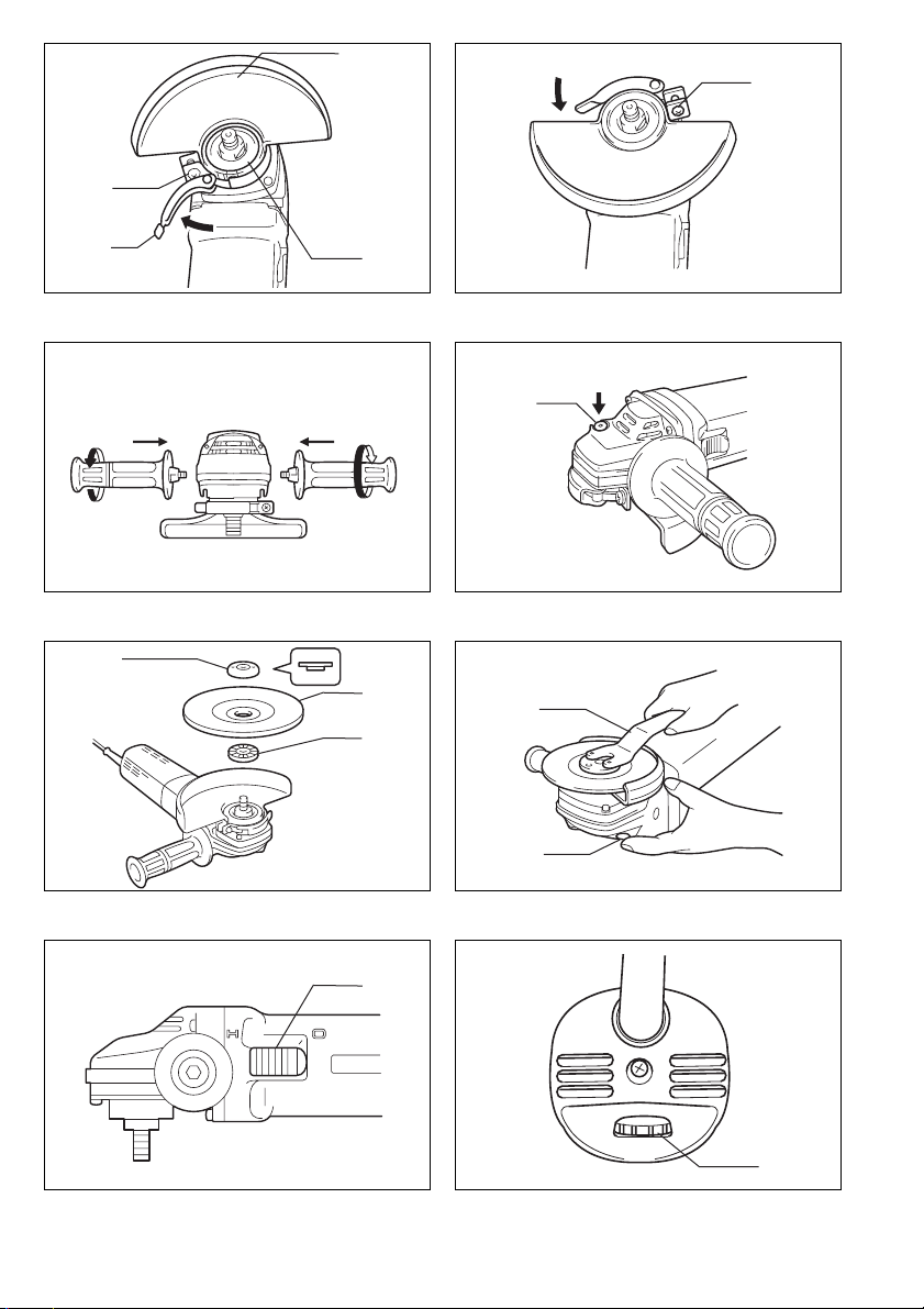
Installing wheel guard (Fig. 1 & 2)
Important:
Always be sure that the tool is switched off and
unplugged before installing or removing the wheel guard.
Pull the lever in the direction of the arrow after loosening
the screw.
Install the wheel cover on the bearing box by adjusting
the convex of the wheel cover to the concave of the bearing box. Turn the wheel cover by 180 degrees. Fasten it
with the screw after pulling lever in the direction of the
arrow for the working purpose, the setting angle of the
wheel cover can be adjusted with the lever.
Removing wheel cover
Follow the installation procedure in reverse to remove the
wheel cover.
Installing side grip (auxiliary handle) (Fig. 3)
Important:
Always be sure that the tool is switched off and
unplugged before installing or removing the side grip.
Always install the side grip on the tool securely before
operation. The side grip can be installed on either side of
the tool, whichever is convenient and keeps the guard
properly positioned. Always hold the tool’s switch handle
and the side grip firmly with both hands during operation.
Shaft lock (Fig. 4)
Press the shaft lock to prevent spindle rotation when
installing or removing accessories.
CAUTION:
Never actuate the shaft lock when the spindle is moving.
The tool may be damaged.
Installing or removing depressed center wheel
(Fig. 5 & 6)
Important:
Always be sure that the tool is switched off and
unplugged before installing or removing the wheel.
Mount the inner flange onto the spindle. Fit the wheel on
over the inner flange and screw the lock nut onto the
spindle.
To tighten the lock nut, press the shaft lock firmly so that
the spindle cannot revolve, then use the lock nut wrench
and securely tighten clockwise. To remove the wheel, follow the installation procedure in reverse.
Switch action (Fig. 7)
CAUTION:
Before plugging in the tool, always check to see that the
switch actuates properly and returns to the ‘‘O (OFF)’’
position when the rear of the switch lever is depressed.
To start the tool, slide the switch lever toward the ‘‘I (ON)’’
position. For continuous operation, press the front of the
switch lever to lock it. To stop the tool, press the rear of
the switch lever, then slide it toward the ‘‘O (OFF)’’ position.
Speed adjusting dial (For model 9566CV) (Fig. 8)
The rotating speed can be changed by turning the speed
adjusting dial to a given number setting from 1 to 5.
Higher speed is obtained when the dial is turned in the
direction of number 5. And lower speed is obtained when
it is turned in the direction of number 1. Refer to the table
below for the relationship between the number settings
on the dial and the approximate rotating speed.
-1
Number min
14,000
25,000
36,500
48,000
59,000
CAUTION:
• If the tool is operated continuously at low speeds, the
motor will get overloaded and heated up.
• The speed adjusting dial can be turned only as far as 5
and back to 1. Do not force it past 5 or 1, or the speed
adjusting function may no longer work.
The tools equipped with electronic function are easy to
operate because of the following features.
• Constant speed control
Electronic speed control for obtaining constant speed.
Possible to get fine finish, because the rotating speed
is kept constantly even under the loaded condition.
• Soft start feature
Safety and soft start because of suppressed starting
shock.
• Overload protector
When the tool would be employed over the admissible
load, it will stop automatically to protect the motor and
wheel. When the load will come to the admissible level
again, the tool can be started automatically.
(R.P.M.)
Operation (Fig. 9)
CAUTION:
After operation, always switch off the tool and wait until
the wheel has come to a complete stop before putting the
tool down.
Hold the tool firmly with both hands. Turn the tool on and
then apply the wheel or disc to the workpiece.
In general, keep the edge of the wheel or disc at an angle
of about 15° – 30° to the workpiece surface. During the
break-in period with a new wheel, do not work the tool in
the B direction or it will cut into the workpiece. Once the
edge of the wheel has been rounded off by use, the
wheel may be worked in both A and B directions.
WARNING:
• It should never be necessary to force the tool. The
weight of the tool applies adequate pressure. Forcing
and excessive pressure could cause dangerous wheel
breakage.
• Continued use of a worn-out wheel may result in wheel
explosion and serious personal injury.
6

MAINTENANCE
CAUTION:
Always be sure that the tool is switched off and
unplugged before carrying out any work on the tool.
Repair and maintenance (Fig. 10)
The tool and its opening vents for cooling air have to be
always kept clean. When the foreign matters clog such
parts, they have to be taken off.
To maintain product safety and reliability, repairs, maintenance or adjustment should be carried out by a Makita
Authorized Service Center.
7

27. Cutting discs must not be subjected to any lateral pressure.
SAVE THESE INSTRUCTIONS.
OPERATING INSTRUCTIONS
Installing wheel guard (Fig. 1 & 2)
Important:
Always be sure that the tool is switched off and
unplugged before installing or removing the wheel guard.
Pull the lever in the direction of the arrow after loosening
the screw.
Install the wheel cover on the bearing box by adjusting
the convex of the wheel cover to the concave of the bearing box. Turn the wheel cover by 180 degrees. Fasten it
with the screw after pulling lever in the direction of the
arrow for the working purpose, the setting angle of the
wheel cover can be adjusted with the lever.
Removing wheel cover
Follow the installation procedure in reverse to remove the
wheel cover.
Installing side grip (auxiliary handle) (Fig. 3)
Important:
Always be sure that the tool is switched off and
unplugged before installing or removing the side grip.
Always install the side grip on the tool securely before
operation. The side grip can be installed on either side of
the tool, whichever is convenient and keeps the guard
properly positioned. Always hold the tool’s switch handle
and the side grip firmly with both hands during operation.
Shaft lock (Fig. 4)
Press the shaft lock to prevent spindle rotation when
installing or removing accessories.
CAUTION:
Never actuate the shaft lock when the spindle is moving.
The tool may be damaged.
Installing or removing depressed center wheel
(Fig. 5 & 6)
Important:
Always be sure that the tool is switched off and
unplugged before installing or removing the wheel.
Mount the inner flange onto the spindle. Fit the wheel on
over the inner flange and screw the lock nut onto the
spindle.
To tighten the lock nut, press the shaft lock firmly so that
the spindle cannot revolve, then use the lock nut wrench
and securely tighten clockwise. To remove the wheel, follow the installation procedure in reverse.
Switch action (Fig. 7)
CAUTION:
Before plugging in the tool, always check to see that the
switch actuates properly and retur ns to the ‘‘O (OFF)’’
position when the rear of the switch lever is depressed.
To start the tool, slide the switch lever toward the ‘‘I (ON)’’
position. For continuous operation, press the front of the
switch lever to lock it. To stop the tool, press the rear of
the switch lever, then slide it toward the ‘‘O (OFF)’’ position.
Speed adjusting dial (For model 9566CV) (Fig. 8)
The rotating speed can be changed by turning the speed
adjusting dial to a given number setting from 1 to 5.
Higher speed is obtained when the dial is turned in the
direction of number 5. And lower speed is obtained when
it is turned in the direction of number 1. Refer to the table
below for the relationship between the number settings
on the dial and the approximate rotating speed.
-1
Number min
14,000
25,000
36,500
48,000
59,000
CAUTION:
• If the tool is operated continuously at low speeds, the
motor will get overloaded and heated up.
• The speed adjusting dial can be turned only as far as 5
and back to 1. Do not force it past 5 or 1, or the speed
adjusting function may no longer work.
The tools equipped with electronic function are easy to
operate because of the following features.
• Constant speed control
Electronic speed control for obtaining constant speed.
Possible to get fine finish, because the rotating speed
is kept constantly even under the loaded condition.
• Soft start feature
Safety and soft start because of suppressed starting
shock.
• Overload protector
When the tool would be employed over the admissible
load, it will stop automatically to protect the motor and
wheel. When the load will come to the admissible level
again, the tool can be started automatically.
(R.P.M.)
Operation (Fig. 9)
CAUTION:
After operation, always switch off the tool and wait until
the wheel has come to a complete stop before putting the
tool down.
Hold the tool firmly with both hands. Turn the tool on and
then apply the wheel or disc to the workpiece.
In general, keep the edge of the wheel or disc at an angle
of about 15° – 30° to the workpiece surface. During the
break-in period with a new wheel, do not work the tool in
the B direction or it will cut into the workpiece. Once the
edge of the wheel has been rounded off by use, the
wheel may be worked in both A and B directions.
WARNING:
• It should never be necessary to force the tool. The
weight of the tool applies adequate pressure. Forcing
and excessive pressure could cause dangerous wheel
breakage.
• Continued use of a worn-out wheel may result in wheel
explosion and serious personal injury.
6

MAINTENANCE
CAUTION:
Always be sure that the tool is switched off and
unplugged before carrying out any work on the tool.
Repair and maintenance (Fig. 10)
The tool and its opening vents for cooling air have to be
always kept clean. When the foreign matters clog such
parts, they have to be taken off.
To maintain product safety and reliability, repairs, maintenance or adjustment should be carried out by a Makita
Authorized Service Center.
7

FRANÇAIS
Descriptif
1 Carter de protection
2Vis
3Levier
4 Boîtier de roulement
5 Appuyer
6 Obturateur de tige
SPECIFICATIONS
Diamètre de la meule à
moyeu déporté/Filetage de
l’arbre
-1
Vitesse à vide (min
) 9 000 4 000 – 9 000
Longueur totale 299 mm 299 mm
Poids net 1,8 kg 1,8 kg
• Etant donné l’évolution constante de notre programme
de recherche et de développement, les spécifications
contenues dans ce manuel sont sujettes à modification
sans préavis.
• Note : Les spécifications peuvent varier suivant les
pays.
Utilisations
L'outil est conçu pour la coupe, le meulage et le ponçage
des matériaux de métal et de pierre, sans utilisation
d'eau.
Alimentation
L’outil ne devra être raccordé qu’à une alimentation de la
même tension que celle qui figure sur la plaque signalétique, et il ne pourra fonctionner que sur un courant secteur monophasé. Réalisé avec une double isolation, il est
conforme à la réglementation européenne et peut de ce
fait être alimenté sans mise à la terre.
Consignes de sécurité
Pour votre propre sécurité, repor tez-vous aux consignes
de sécurité qui accompagnent l’outil.
CONSIGNES DE SÉCURITÉ
ADDITIONNELLES POUR L’OUTIL
1. Portez toujours une protection des yeux et de
l’ouïe. Veuillez porter également toute autre protection personnelle nécessaire : masque à poussière, gants, casque, tablier. etc. En cas de doute
sur la nécessité de porter une protection donnée, portez-la.
2. Assurez-vous toujours que l’outil est hors ten-
sion et débranché avant d’effectuer tout travail
sur l’outil.
3. Laissez les protections en place.
4. N’utilisez que des disques dont la vitesse maxi-
mum d’opération est au moins aussi élevée que
l’indication “No Load RPM” (t/min à vide) inscrite sur la plaque-marque de l’outil. Lors de
l’utilisation d’une meule à découper, assurezvous qu’elle est armée de fibre de verre.
5. Avant l’utilisation, vérifiez soigneusement la pré-
sence de fissures ou de dommages sur le disque. Remplacez immédiatement tout disque
fissuré(e) ou endommagé(e).
7 Contre-écrou
8 Meule à moyeu déporté
9 Flasque intérieur
10 Clé à écrou de blocage
11 Obturateur de tige
12 Levier de l’interrupteur
13 Entrée d’air
14 Sortie d’air
15 Cadran de réglage de la
vitesse
150 mm M14 9566C 9566CV
6. Suivez les instructions du fabricant pour un
montage adéquat et une utilisation appropriée
des disques. Manipulez et rangez les disques
soigneusement.
7. N’utilisez pas de bagues de réduction ou d’adaptateurs pour les roues de ponçage dont le trou
central est grand.
8. N’utilisez que les flasques spécifiés pour cet
outil.
9. Veillez à ne pas endommager l’arbre, le flasque
(tout particulièrement la surface d’installation)
ou l’écrou de sûreté. L’endommagement de ces
pièces peut causer le bris du disque.
10. Dans le cas des outils conçus pour les disques à
trou fileté, assurez-vous que la longueur du filetage du disque correspond à celle de l’arbre.
11. Avant d’utiliser l’outil sur la pièce à travailler,
procédez à un test en faisant tourner l’outil dans
un endroit sûr à sa vitesse à vide maximum pendant au moins 30 secondes. Arrêtez-le immédiatement en cas de vibration ou de rotation
déséquilibrée indiquant la possibilité d’une mauvaise installation ou d’un disque mal équilibré.
Vérifiez l’outil pour identifier la cause.
12. Vérifiez que la pièce à travailler est adéquatement supportée.
13. Tenez l’outil fermement.
14. Gardez les mains éloignées des pièces en rotation.
15. Assurez-vous que le disque n’entre pas en contact avec la pièce à travailler avant de mettre
l’interrupteur sous tension.
16. Utilisez la face du disque spécifiée pour effectuer le meulage.
17. N’utilisez pas de disque de découpage pour
l’aiguisage latéral.
18. Prenez garde aux étincelles. Tenez l’outil de telle
sorte que les étincelles ne jaillissent pas vers
vous, vers quelqu’un d’autre ou vers un matériau inflammable.
19. N’oubliez pas que le disque continue de tourner
une fois l’outil éteint.
20. Ne touchez pas la pièce immédiatement après
l’opération ; elle peut être extrêmement chaude
et brûler votre peau.
8

21. Placez l’outil de telle sorte que le cordon d’alimentation demeure en tout temps derrière pendant l’utilisation.
22. Si le lieu de travail est extrêmement chaud et
humide, ou fortement pollué de poussières conductrices, utilisez un disjoncteur (30 mA) pour
assurer la sécurité de l’utilisateur.
23. N’utilisez l’appareil avec aucun matériau contenant de l’amiante.
24. N’utilisez pas d’eau ou de lubrifiant à meulage.
25. Assurez-vous que les orifices d’aération sont
maintenus dégagés lorsque vous travaillez dans
des conditions poussiéreuses. S’il devient
nécessaire d’enlever la poussière, débranchez
d’abord l’outil de la prise d’alimentation, et prenez garde d’endommager les pièces internes
(utilisez un objet non métallique).
26. Lors de l'utilisation d'une meule à découper, travaillez toujours avec un protecteur de meule collecteur de poussière conforme aux
réglementations locales.
27. Les meules à découper ne doivent subir aucune
pression latérale.
CONSERVEZ CES INSTRUCTIONS.
MODE D’EMPLOI
Montage du carter de protection (Fig. 1 et 2)
Important :
Vérifiez toujours que l’outil est arrêté et qu’il est débranché du secteur avant d’installer ou de retirer le carter de
protection.
Tirer le levier dans le sens de la flèche après avoir desserré la vis.
Installer le car ter de protection sur le boîtier de roulement
en ajustant la partie convexe du carter de protection à la
partie concave du boîtier de roulement. Tourner le carter
de protection de 180 degrés. Fixez-le avec la vis après
avoir tiré le levier dans le sens indiqué par la flèche.
L’angle du carter de protection peut être ajusté en fonction du travail à effectuer, à l’aide du levier.
Retrait du carter de protection
Pour retirer le carter de protection, suivre la procédure
d’installation en sens inverse.
Montage de la poignée latérale
(poignée auxiliaire) (Fig. 3)
Important :
Vérifiez toujours que l’outil est arrêté et qu’il est débranché du secteur avant d’installer ou de retirer la poignée
latérale.
Toujours fixer fermement la poignée latérale à l’outil
avant de l’utiliser. La poignée latérale peut être installée
d’un côté comme de l’autre de l’outil, du côté le plus pratique et qui permet de garder le carter de protection en
position adéquate. En cours d’utilisation, toujours saisir
fermement l’outil à deux mains par la poignée d’interrupteur et par la poignée latérale.
Bouton de blocage (Fig. 4)
Appuyez sur le bouton de blocage pour éviter que l’axe
ne tourne lors de l’installation ou du retrait des accessoires.
ATTENTION :
N’actionnez jamais le bouton de blocage lorsque l’axe
est en mouvement. Vous pourriez endommager l’outil.
Pose et dépose de la meule à centre concave
(Fig. 5 et 6)
Important :
Assurez-vous toujours que le contact est coupé et l’outil
débranché avant de poser ou de retirer la meule.
Montez la flasque intérieure sur l’axe. Installez la meule
sur la flasque intérieure et vissez l’écrou de blocage sur
l’axe.
Pour serrer l’écrou, appuyez fermement sur le bouton de
blocage de façon que l’arbre ne puisse pas tourner, puis,
à l’aide de la clé à ergots, serrez à fond en tournant vers
la droite. Pour retirer la meule, procédez en ordre
inverse.
Interrupteur (Fig. 7)
ATTENTION :
Avant de brancher l'outil, assurez-vous toujours que
l'interrupteur fonctionne correctement et retourne en
position d'arrêt “O (OFF)” lors de la pression sur la partie
arrière du levier de l'interrupteur.
Pour démarrer l'outil, faites glisser le levier de l'interrupteur sur la position "I" (marche). Pour un fonctionnement
continu, appuyez sur la partie avant du levier de l'interrupteur pour le verrouiller. Pour arrêter l'outil, appuyez
sur la partie arr ière du levier de l'interrupteur puis faitesle glisser sur la position “O (OFF)”.
Cadran de réglage de la vitesse (pour 9566CV)
(Fig. 8)
La vitesse de rotation peut être modifiée en tournant le
cadran de réglage de la vitesse sur un numéro de
réglage donné, de 1 à 5.
Une vitesse plus élevée est obtenue lorsque le cadran
est tourné dans le sens du numéro 5.
Une vitesse plus basse est obtenue lorsqu’il est tourné
dans le sens du numéro 1.
Reportez-vous au tableau qui suit pour le rapport entre
les réglages numérotés sur le cadran et la vitesse
approximative de rotation.
-1
Numéro min
14 000
25 000
36 500
48 000
59 000
ATTENTION :
• Le moteur sera surchargé et chauffera si l'outil est
constamment utilisé à vitesse réduite.
Le cadran de réglage de la vitesse ne peut pas être
•
tourné plus haut que 5 ou plus bas que 1. N’essayez
pas de le placer au-delà de 5 ou en dessous de 1,
sinon le réglage de la vitesse risque de ne plus fonctionner.
(R.P.M.)
9

Les outils dotés de fonctions électroniques sont faciles à
utiliser grâce aux caractéristiques suivantes.
• Commande de vitesse constante
Commande électronique de la vitesse pour l’obtention
d’une vitesse constante. Permet la précision du travail
de finition, puisque la vitesse de rotation est maintenue
constante même en condition de charge.
• Démarrage en douceur
Sécurité et douceur du démarrage grâce à la suppression du “choc de démarrage”.
• Protecteur de surcharge
Lorsque l’outil est utilisé avec une charge qui excède la
limite admissible, il s’arrête automatiquement pour protéger le moteur et le disque. L’outil peut être redémarré
automatiquement lorsque la charge revient au niveau
admissible.
Utilisation (Fig. 9)
ATTENTION :
Après l’utilisation, éteignez toujours l’outil et attendez
que la meule soit parvenue à un arrêt complet avant de
poser l’outil.
Tenez l’outil fermement à deux mains. Mettez “EN MARCHE” et appliquez ensuite la meule ou le disque sur la
pièce à travailler.
D’une façon générale, gardez le bord de la meule ou du
disque selon un angle d’environ 15° – 30° avec la surface
à meuler. Lorsque vous commencez à utiliser une meule
neuve, ne faites pas agir votre meuleuse dans la direction B car la meule mordrait dans la surface à meuler.
Attendez que le bord de la meule ait été émoussé par
l’usage avant d’utiliser votre outil dans l’une ou l’autre
direction A ou B.
AVERTISSEMENT :
• Il n’est jamais nécessaire de forcer sur l’outil. Son poids
fournit une pression surffisante. Si vous exercez une
pression excessive, vous risquez de briser votre meule.
• Le fait de continuer à utiliser un disque usé peut provoquer une explosion et des blessures graves.
ENTRETIEN
ATTENTION :
Avant toute intervention, assurez-vous que le contact est
coupé et l’outil débranché.
Réparation et entretien (Fig. 10)
L’outil et ses ouvertures de ventilation pour le refroidissement doivent être gardés propres en tout temps. Lorsque
des substances étrangères obstruent de tels endroits,
elles doivent être retirées.
Pour maintenir la sécurité et la fiabilité du machines, les
réparations, l’entretien ou les réglages doivent être effectués par le Centre d’Entretien Makita.
10

DEUTSCH
Übersicht
1 Schutzhaube
2 Schraube
3 Hebel
4 Lagergehäuse
5Drücken
TECHNISCHE DATEN
Scheibendurchmesser /
Spindelgewinde
-1
Leerlaufdrehzahl (min
Gesamtlänge 299 mm 299 mm
Nettogewicht 1,8 kg 1,8 kg
• Wir behalten uns vor, Änderungen im Zuge der Entwicklung und des technischen Fortschritts ohne vorherige Ankündigung vorzunehmen.
• Hinweis: Die technischen Daten können von Land zu
Land abweichen.
Vorgesehene Verwendung
Die Maschine ist für das Schneiden und Schleifen von
Metall- und Steinmaterial ohne Verwendung von Wasser
vorgesehen.
Netzanschluß
Die Maschine darf nur an die auf dem Typenschild angegebene Netzspannung angeschlossen werden und
arbeitet nur mit Einphasen- Wechselspannung. Sie ist
entsprechend den Europäischen Richtlinien doppelt
schutzisoliert und kann daher auch an Steckdosen ohne
Erdanschluß betrieben werden.
Sicherheitshinweise
Lesen und beachten Sie diese Hinweise, bevor Sie das
Gerät benutzen.
) 9 000 4 000 – 9 000
ZUSÄTZLICHE
SICHERHEITSREGELN FÜR DAS WERKZEUG
1. Tragen Sie stets eine Schutzbrille und Gehör-
schutz. Andere persönliche Schutzvorrichtungen wie Staubmaske, Handschuhe, Helm und
Schürze sind bei Bedarf zu tragen. Im Zweifelsfall ist das Tragen der Schutzvorrichtungen zu
empfehlen.
2. Vergewissern Sie sich vor Ausführung von
Arbeiten am Werkzeug stets, dass es ausgeschaltet und vom Stromnetz getrennt ist.
3. Unterlassen Sie das Abmontieren von Schutz-
vorrichtungen.
4. Verwenden Sie nur Trennscheiben der korrekten
Größe und solche, deren maximale Betriebsdrehzahl mindestens so hoch wie die auf dem
Typenschild des Werkzeugs angegebene maximale Leerlaufdrehzahl ist. Verwenden Sie nur
glasfaserverstärkte Scheiben als gekröpfte
Trennschleifscheiben.
6 Spindelarretierung
7 Flanschmutter
8 Gekröpfte Trennschleifscheibe
9 Innenflansch
10 Sicherungsmutterschlüssel
150 mm M14 9566C 9566CV
5. Überprüfen Sie die Trennscheibe vor dem
Betrieb sorgfältig auf Risse oder Beschädigung.
Falls die Trennscheibe Risse oder Beschädigung
aufweist, muss das Teil unverzüglich ausgewechselt werden.
6. Befolgen Sie die Anweisungen des Herstellers
für korrekte Montage und Verwendung von
Trennscheiben. Behandeln und lagern Sie Trennscheiben mit Sorgfalt.
7. Verwenden Sie keine getrennten Reduzierbuchsen oder Adapter zur Anpassung von Schleifscheiben mit großem Lochdurchmesser.
8. Verwenden Sie nur die für dieses Werkzeug vorgeschriebenen Flansche.
9. Achten Sie sorgfältig darauf, dass Spindel,
Flansch (insbesondere die Ansatzfläche) und
Sicherungsmutter nicht beschädigt werden. Eine
Beschädigung dieser Teile kann zu einem Scheibenbruch führen.
10. Wenn eine Trennscheibe mit Gewindebohrung
am Werkzeug montiert werden soll, achten Sie
darauf, dass ihr Gewinde tief genug für die Spindellänge ist.
11. Bevor Sie mit der eigentlichen Bearbeitung eines
Werkstücks beginnen, sollten Sie das Werkzeug
probeweise in einer sicheren Position mindestens 30 Sekunden lang mit der höchsten Leerlaufdrehzahl laufen lassen. Schalten Sie das
Werkzeug sofort aus, falls Vibrationen oder Taumelbewegungen vorhanden sind, die Anzeichen
für schlechte Montage oder eine schlecht ausgewuchtete Trennscheibe sein können. Überprüfen
Sie das Werkzeug zur Ermittlung der Ursache.
12. Vergewissern Sie sich, dass das Werkstück
sicher abgestützt ist.
13. Halten Sie das Werkzeug mit festem Griff.
14. Halten Sie die Hände von rotierenden Teilen fern.
15. Vergewissern Sie sich vor dem Einschalten des
Werkzeugs, dass Trennscheibe nicht das Werkstück berührt.
11 Spindelarretierung
12 Schalthebel
13 Auslassöffnung
14 Einlassöffnung
15 Drehzahl-Stellrad
11
 Loading...